

Page 1

Subsection 08 (TOP END)
TOP END
SERVICE TOOLS
Description Part Number Page
CRANKSHAFT LOCK ING BOLT..................................................... 529 035 617 ........................................... 21
DIAL INDICATOR ADAPTER ......................................................... 529 036 159 ........................................... 6
ENGINE LEAK DOWN TEST KIT ................................................... 529 035 661 ........................................... 6
PISTON CIRCLIP INSTALLER........................................................ 529 035 921 ........................................... 24
PISTON CIRCLIP INSTALLER........................................................ 529 036 083 ........................................... 24
PISTON CIRCLIP INSTALLER........................................................ 529 036 153 ........................................... 24
TDC DIAL IN DICATOR .................................................................. 414 104 700 ........................................... 6
VALVE GUIDE INS TALLER ............................................................ 529 036 140 ........................................... 18
VALVE GUIDE INS TALLER ............................................................ 529 036 269 ........................................... 18
VALVE GUIDE REMOVER (6 MM) ................................................ 529 036 074 ........................................... 18
VALVE GUIDE REMOVER 5 MM .................................................. 529 035 924 ........................................... 18
VALVE SPRING COMPRESSOR CUP............................................ 529 035 764 ........................................... 14
VALVE SPRING COMPRESSOR CUP............................................ 529 036 270 ........................................... 14
VALVE SPRING COMPRESSOR .................................................... 529 035 724 ........................................... 14
SERVICE TOOLS – OTHER SUPPLIER
Description Part Number Page
SNAP-ON PLIERS.............. ............................................................ YA 8230 ........................................... 16
SERVICE PRODUCTS
Description Part Number Page
LOCTITE 767 ( ANTISEIZE LUBRICANT) ......... .............................. 293 800 070 ........................................... 19
vmr2016-419 1
Page 2
Subsection 08 (TOP END)
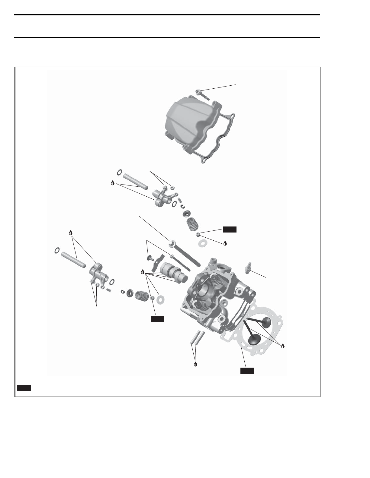
CYLINDER HEAD NO. 1
Engine oil
7 ± 0,8 N•m
(62 ± 7 lbf•in)
12 ± 1 N•m
(106 ± 9 lbf•in)
Engine oil
12 ± 1 N•m
(106 ± 9 lbf•in)
= Component must be replaced when removed.
NEW
tmr2013-068-001_b
See tightening
procedure
10 ± 1 N•m
(89 ± 9 lbf•in)
Engine
oil
NEW
Loctite 648
10 ± 1 N•m
(89 ± 9 lbf•in)
NEW
Engine oil
See ignition
system
Engine oil
NEW
2 vmr2016-419
Page 3
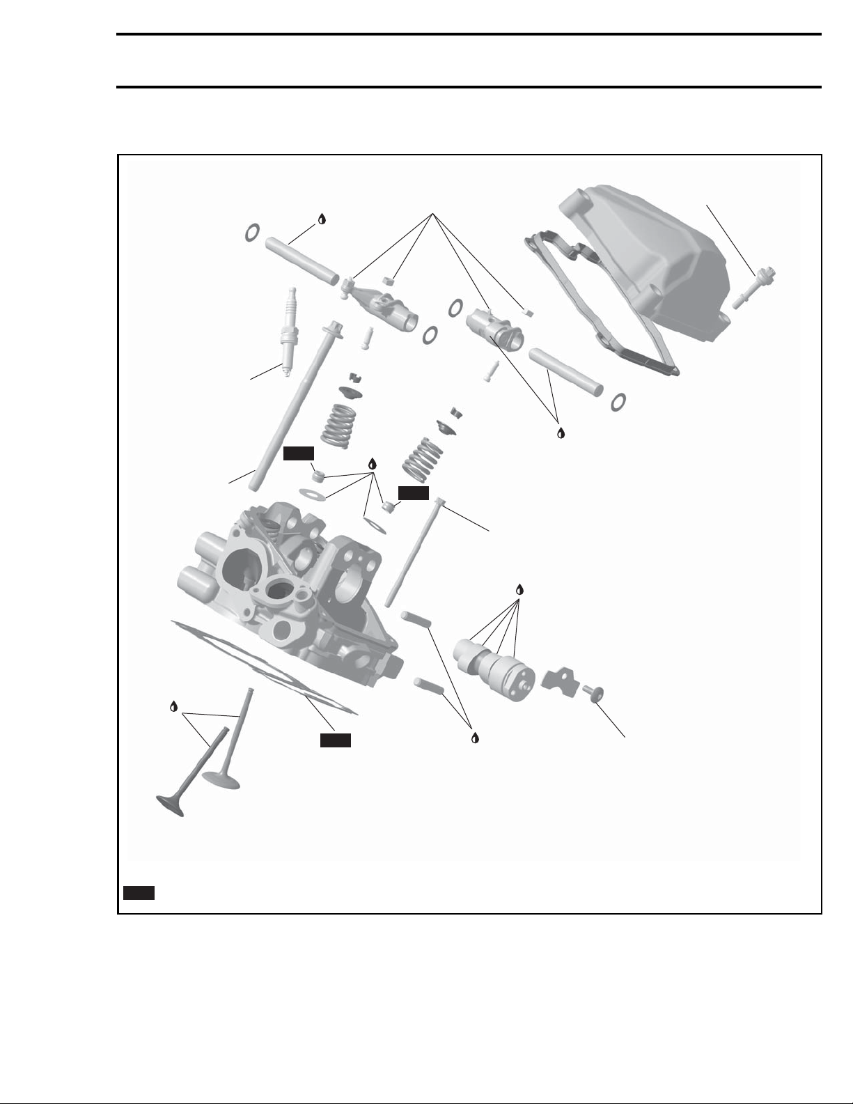
CYLINDER HEAD NO. 2
Engine oil
See ignition
system
12 ± 1 N•m
(106 ± 9 lbf•in)
Subsection 08 (TOP END)
7 ± 0,8 N•m
(62 ± 7 lbf•in)
See tightening
procedure
Engine oil
NEW
NEW
Engine oil
NEW
10 ± 1 N•m
(89 ± 9 lbf•in)
Engine oil
Loctite 648
10 ± 1 N•m
(89 ± 9 lbf•in)
Engine oil
10 ± 1 N•m
(89 ± 9 lbf•in)
= Component must be replaced when removed.
NEW
tmr2013-068-002_b
vmr2016-419 3
Page 4
Subsection 08 (TOP END)
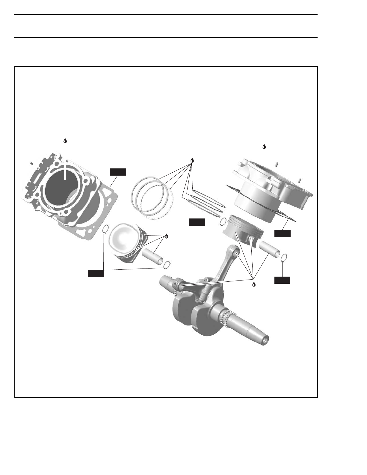
CYLINDERS AND PISTONS
Engine oil
NEW
NEW
Engine oil
NEW
Engine oil
Engine oil
Engine oil
Engine
oil
NEW
NEW
vmr2006-043-003_d
4 vmr2016-419
Page 5
Subsection 08 (TOP END)
GENERAL
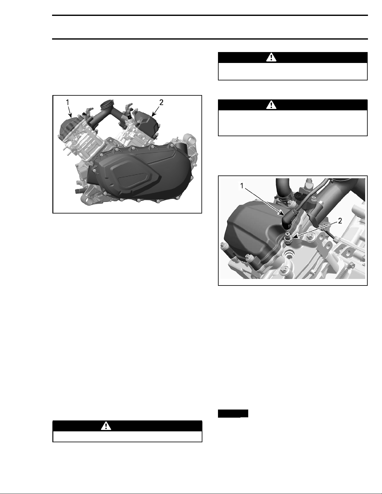
Special reference are made in the text for procedures which are different for cylinder no. 1 and
cylinder no. 2.
Vmr2012-015-002_a
TYPICAL
1. Cylinder 1 (front)
2. Cylinder 2 (rear)
WARNING
Always respect this order for disassembly;
disconnect BLACK (-) cable first.
2. Remove radiator cap.
WARNING
To prevent be
is cool and we
ment before
3. Unplug spark plug cable.
4. Clean spark plug area and remove spark plug
from cylinder head.
ing burned, ensure the radiator
ar the appropriate safety equip-
removing the radiator cap.
When diagnosing an engine problem, always perform a cylinder leak test.
NOTE: Even though the following procedures do
not require the engine removal, many illustrations
show the engine out of the vehicle for more clarity.
IMPORTANT: Note position of parts upon disassembly. This may help to find the root cause of a
problem. A component that is not replaced should
be reinstalled in the same position as originally
mounted.
INSPECTION
LEAK TEST
Before performing the cylinder leak test, verify the
following:
– Clamp(s) tightness
– Radiator and hoses.
NOTE: For best accuracy, the leak test should be
done with the engine at normal operating temperature.
WARNING
Prevent burning yourself on hot engine parts.
tmr2011-013-005_a
1. Spark plug cable
2. Spark plug
5. Remove
VALVE COVER
. See procedure in this
subsection.
6. Rotate crankshaft until piston is at ignition TDC.
7. Turn crankshaft using one of the following two
procedures.
First Procedure
Turn the drive pulley.
Second Procedure
1. Remove plug screw with O-ring from magneto
cover.
2. Use a 14 mm Allen key and turn crankshaft.
NOTICE
Turn only clockwise to avoid loosen-
ing of magneto flywheel Allen screw.
3. Set the piston to precisely ignition TDC.
Preparing the Leak Test
1. Disconnect battery.
vmr2016-419 5
Page 6
Subsection 08 (TOP END)
ENGINE REQUIRED TOOL
All
850 and
1000R
3-007_a
tmr2011-01
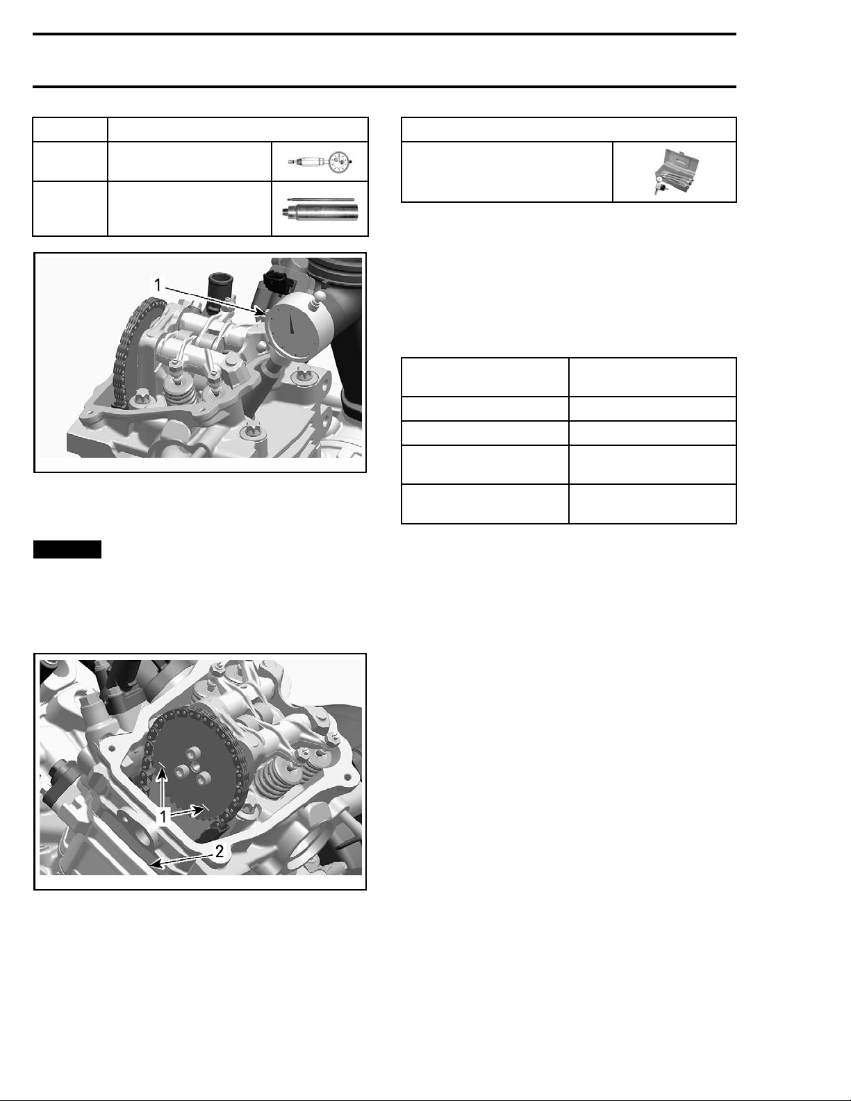
1. TDC dial indicator
TDC DIAL INDICATOR
(P/N 414 104 700
DIAL INDICATOR
ADAPTER (P/N 5
036 159)
)
29
NOTE: If a dial gauge is not available, use a screwdriver or another similarly suitable tool.
NOTICE
ton/cylin
Do not scra
der surface.
tch or damage pis-
NOTE: At ignition TDC the marks on the camshaft
timing gear have to be parallel to cylinder head
base as per following illustration.
tmr2011-013-008_a
1. Marks on camshaft timing gear
2. Cylinder head b ase
Leak Test
1. Install the gauge adapter in the spark plug hole.
REQUIRED TOOL
ENGINE LEAK DOWN TEST
KIT (P/N 529 035 661)
2. Connect to an adequate air supply.
3. Set needle of measuring gauge to zero.
NOTE: All testers have specific instructions on
gauge operation and required pressure.
4. Supply combustion chamber with air pressure.
5. Note the amount or percentage of leakage (depending on tester).
LEAKAGE
PERCENTAGE
0% to 15% Excellent condition
16% to 25%
26% to 40%
41% and higher
Fair condi
Poor cond
ENGINE
CONDITION
Good condition
tion; reduced
engine performance
ition, diagnose
and repair engine
NOTE: To make sure there is no false reading due
to a valve not being perfectly seated, tap each
valve adjustment screw (on the rocker arm) using
a soft hammer.
Diagnos
is
Listen for air leaks.
–Airesca
leaking
ping in intake port/throttle body means
intake valve(s).
– Air escaping in exhaust port means leaking ex-
haust valve(s).
– Air bubbles in the c oolant (radiator) means leak-
ing cylinder head gasket.
–Air/co
olant escaping from cylinder/head means
damag
ed gasket(s) and/or loosened screws.
– Air escaping into crankcase area means exces-
sively worn cylinder and/or broken piston rings.
– Air/oil escaping from crankcase means dam-
aged gasket and/or loosened screws (refer to
BOTTOM END
subsection).
NOTE: For all checkpoints mentioned above, see
appropriate engine section to diagnose and repair
the engine.
Reassembly
Reverse the preparation procedure. Ensure to
respect torque values and use of appropriate
products/lubricants. Refer to exploded views in
other subsections of this manual as required.
6 vmr2016-419
Page 7
Subsection 08 (TOP END)
PROCEDURES
VALVE CO VE R
Valve Cover Ac
Front Cylinder
Refer to
ing.
–Seat
– Console
– RH side panel
– RH inner fender panel
Rear Cylinder
Refer to
–Seat
– Console
–RHsidepane
– LH side panel.
Refer to
pipe.
BODY
BODY
EXH
cess
subsection and remove the follow-
and remove:
l
AUST SYSTEM
and remove exhaust
Installing the Valve Cover
For installation, reverse the removal procedure.
However, pay attention to the following.
Tighten valve cover retaining screws to specified
torque in a criss-cross sequence.
TIGHTENING TO
Valve cover retaining
screws
RQUE
7N•m ±0.8N•m
(62 lbf•in ±7
lbf•in)
ROCKER ARM
Removing the Rocker Arm
1. Remove
subsection.
2. Refer to
move follow
– Timing chain tensioner
– Camshaft timing gear.
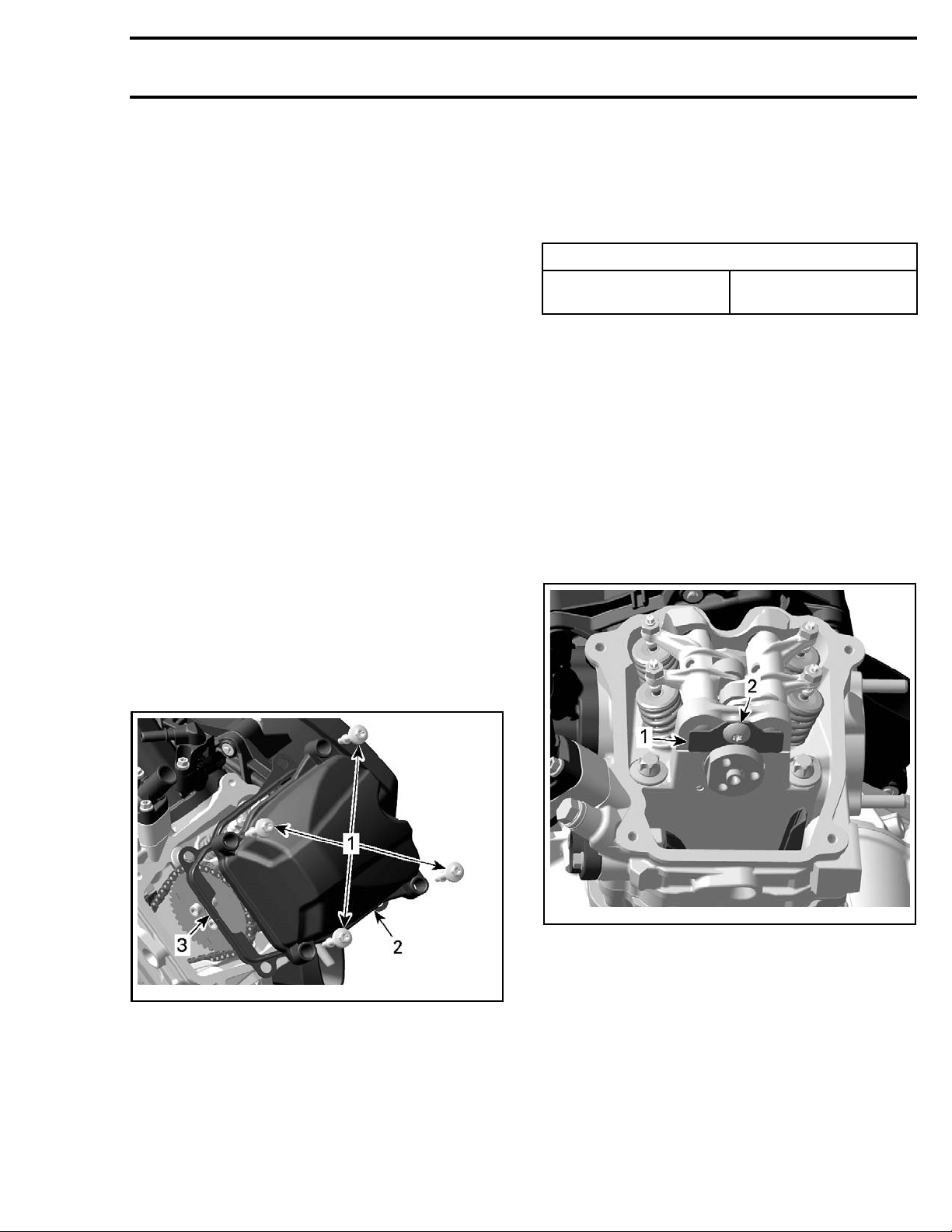
3. Remove pan head screw and camshaft retaining plate.
VALVE COVER
ING CHAIN
TIM
ing parts:
. See procedure in this
subsection and re-
Removing the Valve Cover
Remove:
– Valve cover screws
– Valve cover
– Gasket.
vmr2016-033-001_a
TYPICAL — FRONT CYLINDER SHOWN
1. Valve cover screws
2. Valve cover
3. Gasket
vmr2016-033-002_a
1. Camshaft retaining plate
2. Pan head screw
4. Remove rocker arm shafts.
Inspecting the Valve Cover
Check the gasket on the valve cover if it is brittle,
cracked or hard. If so, replace the gasket.
vmr2016-419 7
Page 8
Subsection 08 (TOP END)
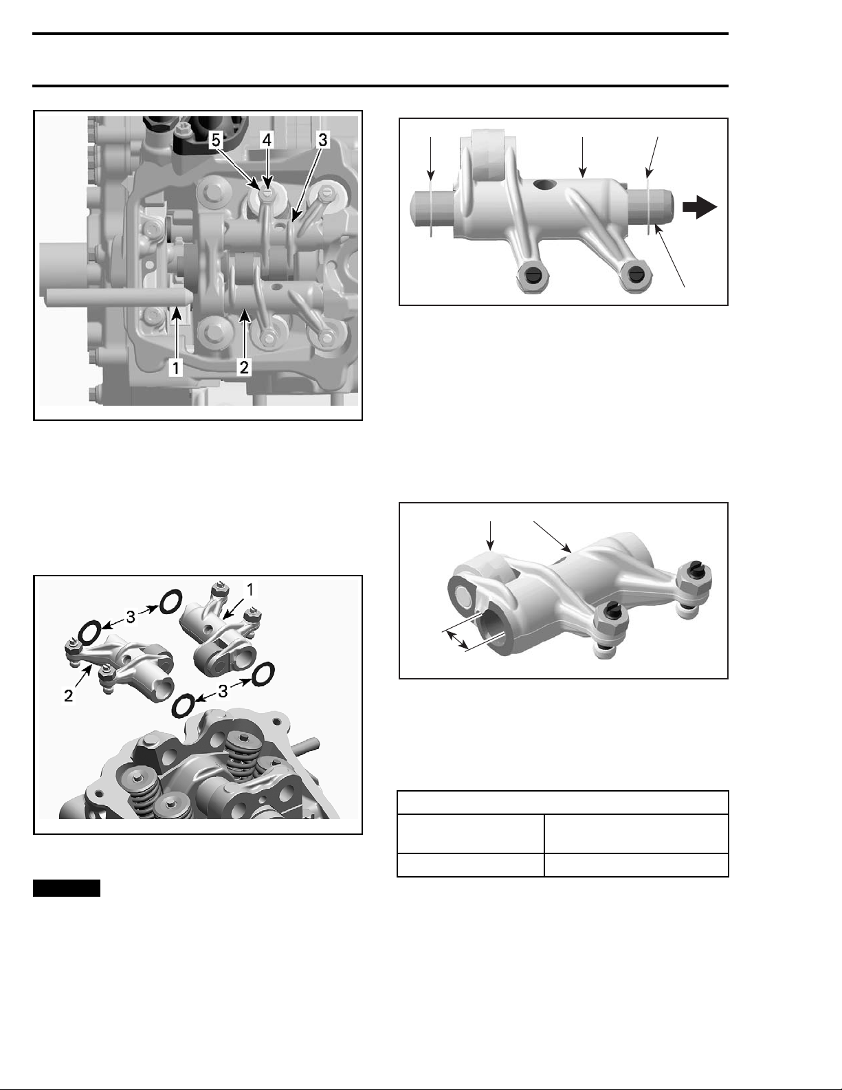
vmr2006-043-016_a
1. Rocker arm shaft
2. Rocker arm (exhaust side)
3. Rocker arm (intake side)
4. Adjustment screw
5. Lock nut
5. Remove rocker arm assembly (exhaust side
and intake side) with adjustment screws and
lock nuts.
6. Remove thrust washers.
2
11
3
R400motr67A
1. 2 thrust washers
2. Rocker arm (exhaust side)
3. Cylinder head ( spark plug side)
4. Big taper to spark plug side
4
Inspecting the Rocker Arm
Inspect each rocker arm for cracks and scored friction surfaces. If so, replace rocker arm assembly.
Check the rocker arm rollers for free movement,
wear and excessive radial play. Replace rocker
arm assembly if necessary.
2
1
tmr2011-013-010_a
1. Rocker arm (exhaust side)
er arm (intake side)
2. Rock
3. Thrust washers
CE
NOTI
Pay attention not to lose thrust
washers or drop them into the timing chain
compartment.
A
R400motr68A
1. Rocker arm (exhaust side)
2. Roller
A. Bore fo
r rocker arm shaft
Measure rocker arm bore diameter. If diameter
is out of specification, change the rocker arm assembly.
ROCKER AR M BORE DIAMETER
NEW
SERVICE LIMIT
12.036 mm to 12.050 mm
(.4739 in to .4744 in)
12.060 mm (.4748 in)
Check adjustment screws for free movement,
cracks and/or excessive play.
8 vmr2016-419
Page 9
1
R400motr69A
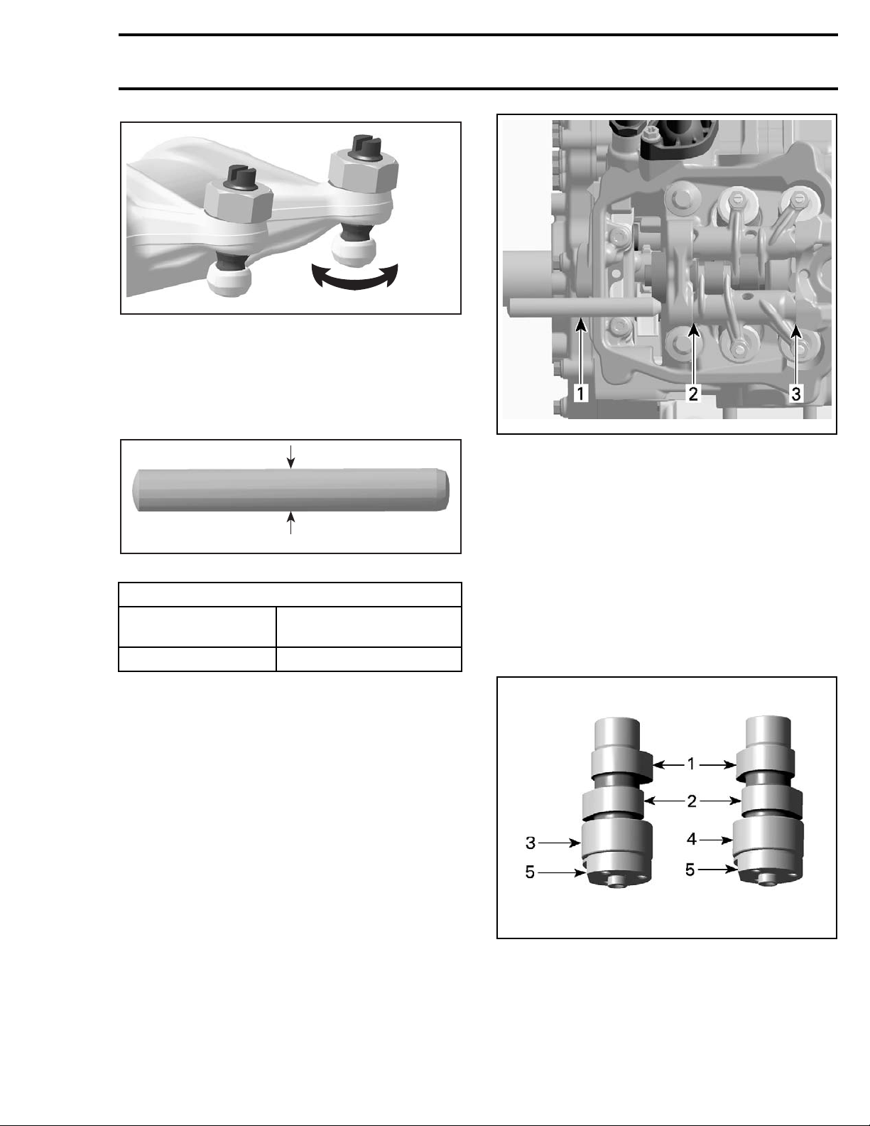
1. Free movement of adjustment screw top
Inspecting the Rocker Arm Shaft
Check for scored friction surfaces; if so, replace
parts.
Measure rocker arm shaft diameter.
Subsection 08 (TOP END)
vmr2006-043-016_b
1. Rocker arm shaft
2. Thrust washer (timing chain side)
3. Thrust washer (spark plug side)
R400motr70A
A. Measure rocker arm shaft diameter here
ROCKER ARM SHAFT DIAMETER
NEW
SERVICE LIMIT
Any area
placeme
worn excessively will require parts re-
nt.
A
12.000 mm to 12.018 mm
(.4724 in to .4731 in)
11.990 mm (.472 in)
Installing the Rocker Arm
NOTE: Us
intake r
1. Apply engine oil on rocker arm shaft.
2. Insert a rocker arm shaft with the chamfered
edge first through rocker arm pin bore.
3. Instal
the pr
side)
4. Push in rocker arm shaft until its chamfer
reaches the end of rocker arm bore.
e the same procedure for exhaust and
ocker arm.
l a thrust washer at timing chain side, then
oper rocker arm (exhaust side or intake
.
5. Place the other thrust washer and push rocker
arm shaft to end position.
6. Install the camshaft retaining plate.
7. Adjust valve clearance, refer to
MAINTENANCE PROCEDURES
PERIODIC
subsection.
CAMSHAFT
NOTE: The engine is equipped with two different
camshafts.
vmr2015-032-001_a
1. Intake cam
ust cam
2. Exha
3. Camshaft of cylinder 1
4. Camshaft of cylinder 2
t spot
5. Fla
Removing the Camshaft
removal procedure is the same for both
The
shafts.
cam
vmr2016-419 9
Page 10
Subsection 08 (TOP END)
NOTICE
Each camshaft is different in design.
Thus, it is important not to mix up any parts of
the camshaft assembly with that of the other
cylinder. Keep parts as a group.
1. Remove valve cover (see
VALVE COVER
in this
subsection).
2. Refer to the
TIMING CHAIN
subsection to re-
move the following parts:
– Chain tensioner
– Camshaft timing gear.
3. Remove the camshaft retaining plate.
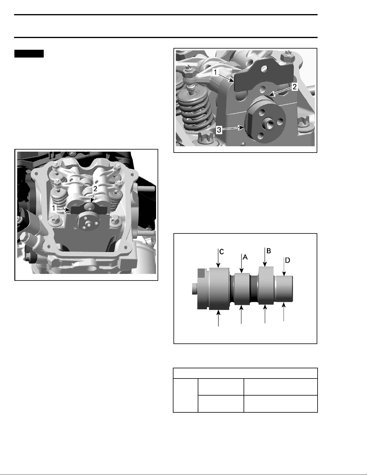
tmr2011-013-014_a
1. Camshaft retaining plate
2. Area for c am shaft lobes
3. Camshaft
Inspecting the Camshaft
Inspecting the Camshaft Lobe
Check each lobe for scoring, scuffing, cracks or
other signs of wear.
Measure camshaft lobe height using a micrometer.
6-033-002_a
vmr201
1. Camshaft retaining plate
2. Pan head screw
der head
3. Cylin
4. Remove rocker arms (see
ROCKER ARM
in
this subsection).
5. Remov
e the camshaft.
NOTE: For removal rotate camshaft so that
intake/exhaust lobe shows to upper side of cylinder head.
vmr2015-032-002_a
A. Camshaft lobe (exhaust valves)
B. Camsha
C. Camshaft journal (timing chain side)
D. Camshaft journal (spark plug side)
ft lobe (intake valves)
CAMSHAFTLOBE(INTAKE)
NEW
31.830 mm to 32.030 mm
570
e
engin
SERVI
LIMIT
CE
31.810 mm (1.2524 in)
(1.2531 in to 1.261 in)
10 vmr2016-419
Page 11
Subsection 08 (TOP END)
850
engine
1000R
engine
570
engine
850
engine
1000R
engine
CAMSHAFT LOBE (
NEW
SERVICE
LIMIT
NEW
SERVICE
LIMIT
CAMSHAFT LOBE (EXHAUST)
NEW
SERVICE
LIMIT
NEW
SERVICE
LIMIT
NEW
SERVICE
LIMIT
INTAKE)
32.890 mm to 33.090 mm
(1.2949 in to 1
32.870 mm (1.2941 in)
32.960 mm to 33.160 mm
(1.2976 in to 1.3055 in)
32.940 mm (1.2969 in)
31.730 mm to 31.930 mm
(1.2492 in to 1.2571 in)
31.710 mm (1.2484 in)
32.950 mm to 33.150 mm
(1.2972 in to 1.3051 in)
32.930 mm (1.2965 in)
32.860 mm to 33.060 mm
(1.2937 in to 1.3016 in)
32.840 mm (1.2929 in)
.3028 in)
CAMSHAFT JOURN
(TIMING CHAIN SIDE)
NEW
SERVICE LIMIT
CAMSHAFT JOURNAL
(SPARK PLUG S
NEW
SERVICE LIMIT
34.959 mm to 34
(1.3763 in to 1.377 in)
34.950 mm (1.376 in)
21.959 mm to 21.980 mm
21.950 mm (.8642 in)
AL
IDE)
(.8645 in to
.975 mm
.8654 in)
Installing the Camshaft
Reverse the removal procedure. Pay attention to
the following details.
NOTICE
design. Do not invert the camshafts during
assembly. Any mix-up of the components will
lead to engine damage.
Place the camshaft retaining plate in the slot of the
camshaft.
The camshafts are not identical in
Measure
CYLIN
to
camshaft bearing in cylinder head. Refer
DER HEAD INSPECTION
in this subsec-
tion.
Inspecting the Camshaft Journal
Check each journal for scoring, scuffing, cracks or
other signs of wear.
Measur
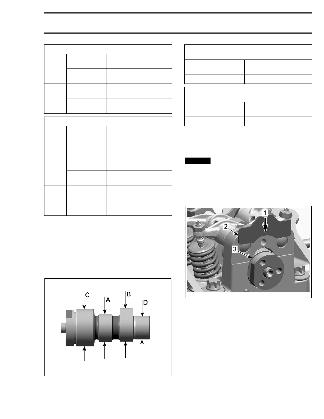
vmr2015-032-002_a
A. Camshaft lobe (exhaust valves)
B. Camshaft lobe (intake valves)
C. Camshaft journal (timing chain side)
D. Camshaft journal (spark plug side)
e camshaft journal using a micrometer.
1-013-014_b
tmr201
1. Direction of movement
2. Camshaft retaining plate
3. Slot re
taining camshaft
For other parts, refer to proper installation procedure.
CYLINDER HEAD
Cylinder Head Access
Refer to
Removing the Cylinder Head
1. The removal procedure is the same for both
cylinder heads.
VALVE COVER
in this subsection.
vmr2016-419 11
Page 12
Subsection 08 (TOP END)
2. Drain coolant (refer to
NANCE PROCEDURES
PERIODIC MAINTE-
subsection).
3. Disconnect the coolant hose from the thermostat housing.
NOTE: Before removing cylinder head, blow out
remaining coolant by air pressure. During cylinder head removal, the remaining coolant in cylinder head could overflow into the engine and a little
quantity of coolant could drop into the engine. In
this case, the engine oil will be contaminated.
4. Refer to
EXHAUST SYSTEM
subsection and
disconnect exhaust system head pipe from
cylinder head.
5. Disconnect spark plug wire.
6. Disconnect temperature sensor connector, located at rear cylinder head.
7. Remove the intake manifold. Refer to
MANIFOLD
subsection.
INTAKE
8. Remove the valve cover and its gasket (see
VALVE COVER
9. Refer to the
in this subsection).
TIMING CHAIN
subsection to re-
move the following parts:
– Chain tensioner
– Camshaft timing gear.
10. First remove the M6 cylinder head screws,
then the cylinder head screws M10.
4
2
1
R400motr72A
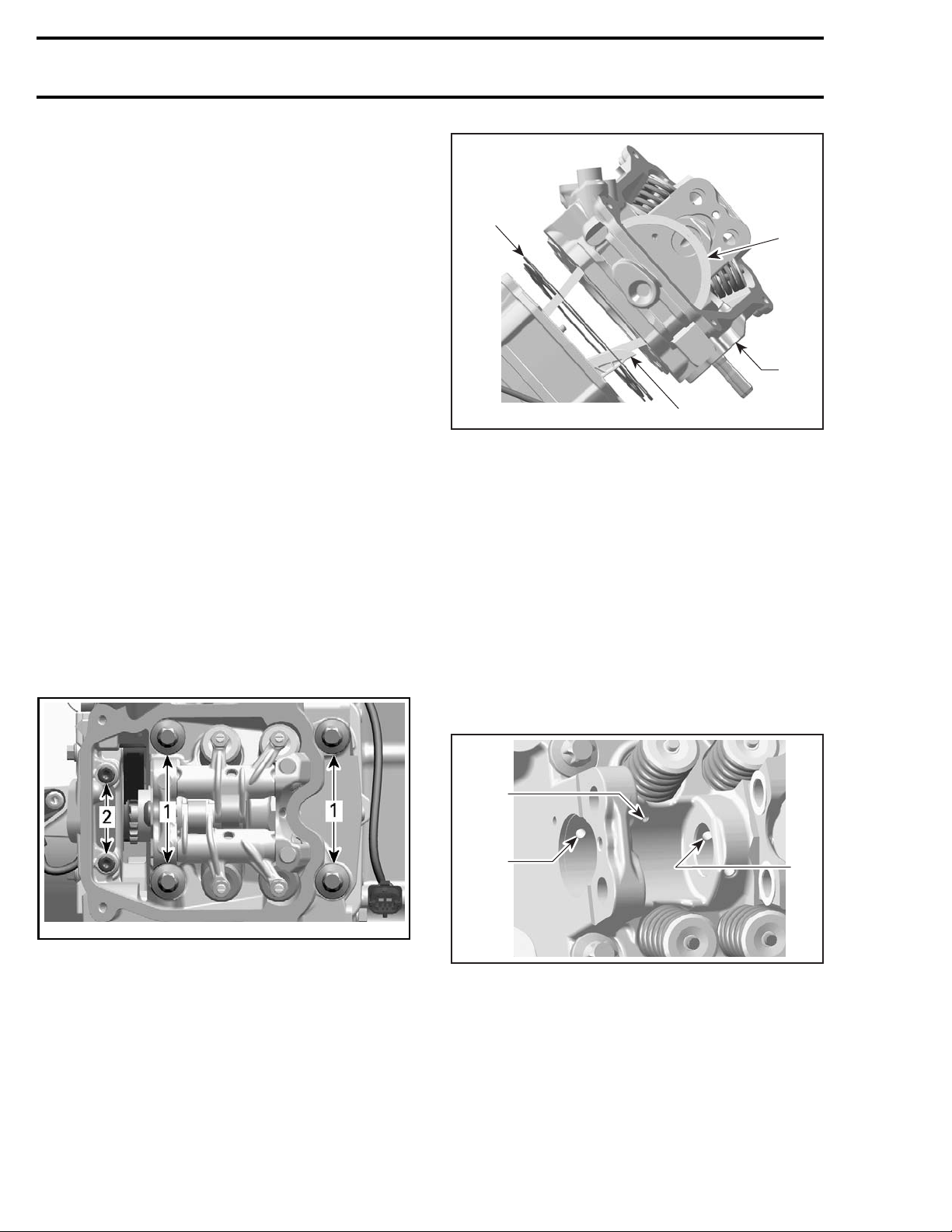
1. Cylinder head
2. Timing chain
3. Chain guide (fixed)
4. Cylinder head gasket
3
Inspecting the Cylinder Head
Inspect timing chain guide (fixed) for wear, cracks
or other damages. Replace if necessary.
Check for cracks between valve seats, if so, replace cylinder head.
Check mating surface between cylinder and cylinder head for contamination. If so, clean both surfaces.
Clean oil support through the cylinder head from
contamination.
1
tmr2011-013-011_a
nder head screws M10
1. Cyli
2. Cylinder head screws M6
11. Pull up cylinder head.
2
R400motr73A
1. Oil port to lubricate camshaft lobes intake/exhaust
2. Oil su
3. Oil supply to camshaft bearing journal (spark plug side)
pply to camshaft bearing journal (timing chain side)
3
12. Remove timing chain guide (fixed).
cting the Cylinder Head Camshaft
13. Rem
12 vmr2016-419
ove and discard the cylinder head gasket.
Inspe
Bearing
Measu
re camshaft bearing in cylinder head.
Page 13
A
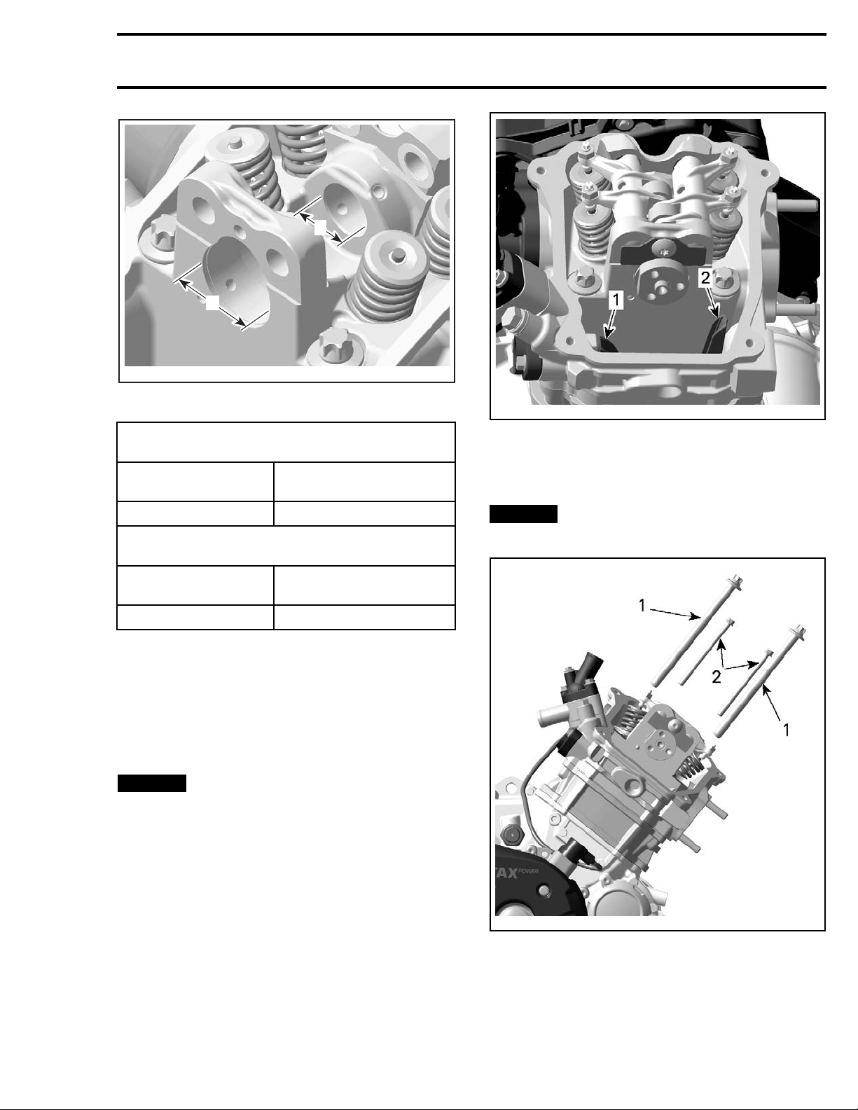
R400motr77A
A. Camshaft bearing (timing chain side)
B. Camshaft bearing (spark plug side)
CAMSHAFT BEARING
(TIMING C
NEW
HAIN SIDE)
35.000 mm to 35.025 mm
(1.378 in
B
to 1.3789 in)
Subsection 08 (TOP END)
vmr2016-033-002_b
1. Timing chain guide (tensioner side) mounted in crankcase
2. Timing chain guide (fixed) between cylinder and cylinder head
Install a NEW cylinder head gasket.
Install cylinder head screws in correct position.
SERVICE LIMIT
35.040 mm (1.3795 in)
CAMSHAFT BEARING
(SPARK PLUG S IDE )
NEW
SERVICE LIMIT
22.000 mm to 22.021 mm
(.8661 in to .867 in)
22.040 mm (.8677 in)
Installing the Cylinder Head
NOTE: Front and rear cylinder heads are not iden-
tical. Never interchange cylinder heads.
Reverse the removal procedure. Pay attention to
the following details.
Ensure dowel pins are in place.
NOTICE
fixed between cylinder and cylinder head.
Timing chain guide (fixed) has to be
NOTICE
Cylinder head screws have different
sizes and lengths.
vmr2015-032-003_a
1. Location no. 1
2. Location no. 2
vmr2016-419 13
Page 14
Subsection 08 (TOP END)
CYLINDER HEAD S
Location no. 1 M10 x 140570
and
850
engines
1000R
engine
Location no. 2 M6 x 85
Location no. 1 M10 x 159
Location no.
CREW IDENTIFICATION
2
M6 x 105
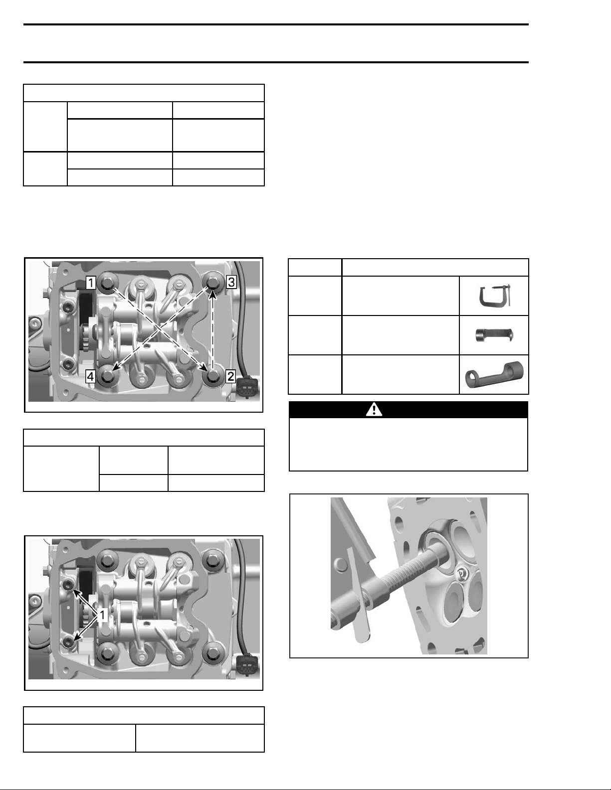
Tighten M10 cylinder head screws FIRST as per
following specifications.
NOTE: Alway
der head scr
s perform one step on all M10 cylin-
ews before going to the next step.
Check timing chain guide (tensioner side) for
movement.
Refer to applicable subsection for installation details of remaining removed parts.
VALVE SP RI NG S
Removing the Valve Spring
1. Refer to following procedures in this subsection
to remove:
–
CAMSHAFT
–
CYLINDER HEAD
2. Remove valve spring.
ENGINE REQUIRED TOOL
All
engines
570
engine
850 and
1000R
engines
VALVE S PRING
COMPRESSOR
(P/N 529 035
VALVE S PRING
COMPRESSOR
(P/N 529 035 764)
VALVE S PRIN
COMPRESSOR CUP
(P/N 529 036 270)
.
724)
CUP
G
tmr2011-013-011_c
TIGHTENING SEQUENCE - M10 CYLINDER HEAD SCREWS
TIGHTENING TORQUE
M10 cylinder
head screws
STEP A
STEP B
20 N•m ± 1 N•m
(15lbf•ft ±1lbf•ft)
180° +/- 5°
Tighten M6 cylinder head screws as per following
specification.
tmr2011-013-011_d
1. M6 Screws
WARNING
Always wear safety glasses when disassembling valve springs. Be careful when unlocking valves. Components could fly away because of the strong spring preload.
R400motr79A
LOCATE VALVE SPRING COMPRESSOR CLAMP IN CENTER OF
THE VALVE
3. Remove valve cotters.
TIGHTENING TORQUE
M6 cylinder head
screws
14 vmr2016-419
10 N•m ± 1 N•m
(89 lbf•in ±9lbf•in)
Page 15
Subsection 08 (TOP END)
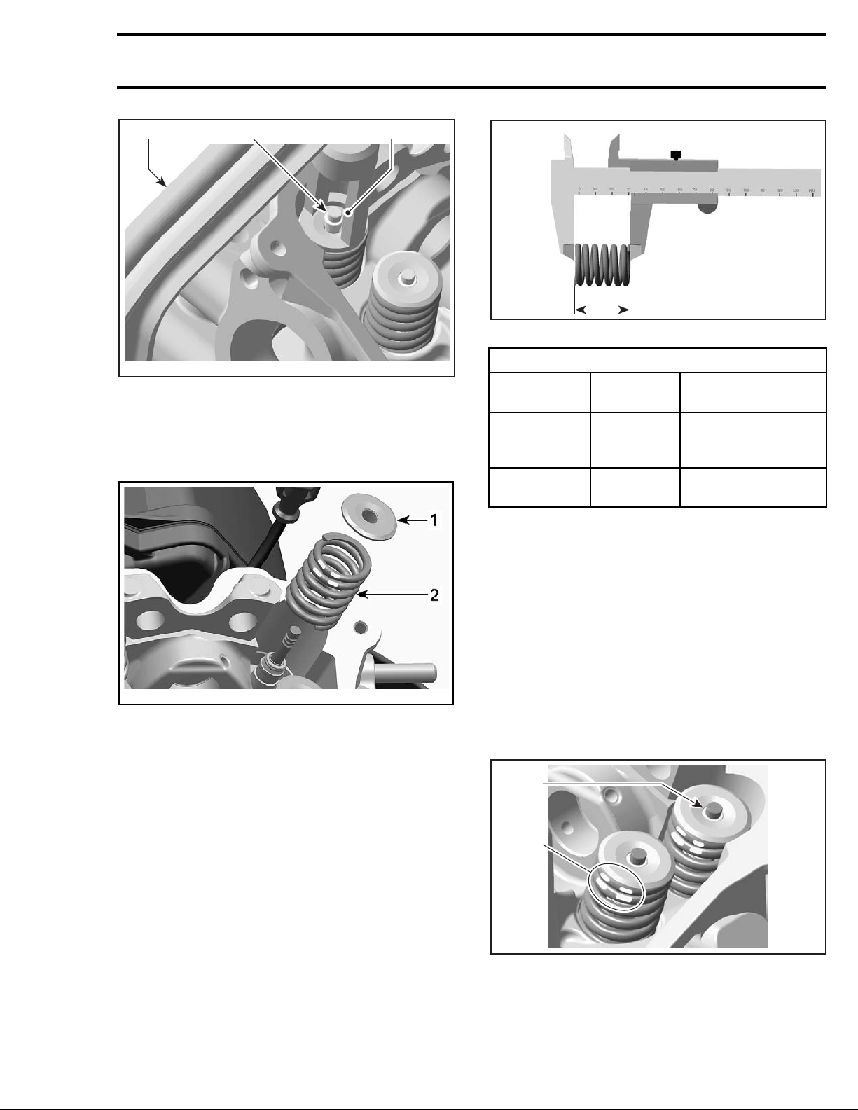
1
R400motr78A
1. Valve spring compressor clamp
2. Valve spring compressor cup
3. Valve cotter
32
4. Remove tools and withdraw valve spring retainer and valve spring.
R400motr80A
A. Valve spring length
VALVESPRINGFREELENGTH
570 ENGINE
850 AND
1000R
ENGINES
ALL
ENGINES
Replace v
alve springs if not within specifications.
A
NOMINAL
NEW
NOMINAL
NEW
Service limit
40.81 mm (1.607 in)
40.41 mm (1.591 in)
39.00 mm (1.535 in)
tmr2011-013-015_a
1. Valve spring retainer
2. Valve
spring
Inspecting the Valve Spring
Check
place
Check valve spring for free length and straightness.
valve spring for visible damage. If so, re-
valve spring.
Installing the Valve Spring
For insta
Pay atten
Coloredareaofthevalvespringmustbeplaced
on top.
To ease installation of cotters, apply oil or grease
on them so that they remain in place while releasing the spring.
NOTE: Va
valve st
R400motr81A
1. Position of th e valve spring
2. Valve cotter
llation, reverse the removal procedure.
tion to the following details.
lve cotter must be properly engaged in
em grooves.
2
1
After spring is installed, ensure it is properly
locked by tapping on valve stem end with a soft
hammer so that valve opens and closes a few
times.
vmr2016-419 15
Page 16
Subsection 08 (TOP END)
NOTICE
An improperly locked valve spring
will cause engine damage.
VALVE S
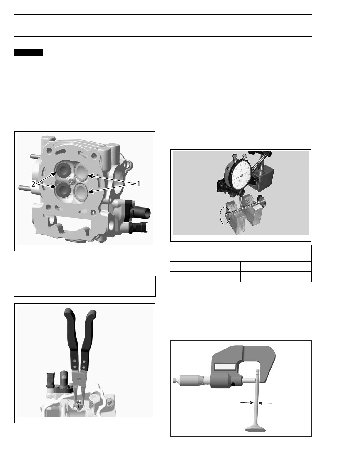
Removing the Valve
1. Remove valve spring, see
this subsection.
2. Push valve stem, then pull valves (intake and
exhaust) out of valve guide.
VALVE SPRING
in
Inspecting the Valve
Whenever valves are removed always inspect
valve guides. Refer to
VALVE GUIDES
subsection.
ValveStemSeal
Always install NEW seals whenever valves are removed.
Inspecting the Valve
Inspect valve surface, check for abnormal s tem
wear and bending. If out of specification, replace
by a new one.
in this
vmr2006-043-021_a
1. Intake valves 31 mm
2. Exhaust
valves 27 mm
3. Remove valve stem seal and discard it.
REQUIRED TOOL
SNAP-ON PLIERS (P/N YA 8230)
mmr2009-115-072_a
VALVE OUT OF ROUND
(INTAKE AND EXHAUST VALVES)
NEW
SERVICE LIMIT
0.005 mm (.0002 in)
0.06 mm (.0024 in)
Inspecting the Valve Stem
Measure valve stem in three places using a micrometer.
Replace valve if valve stem is out of specification
or has other damages such as wear or friction surface.
A
vmr2006-043-023
16
R400motr83A
A. Valve stem diameter
vmr2016-419
Page 17
Subsection 08 (TOP END)
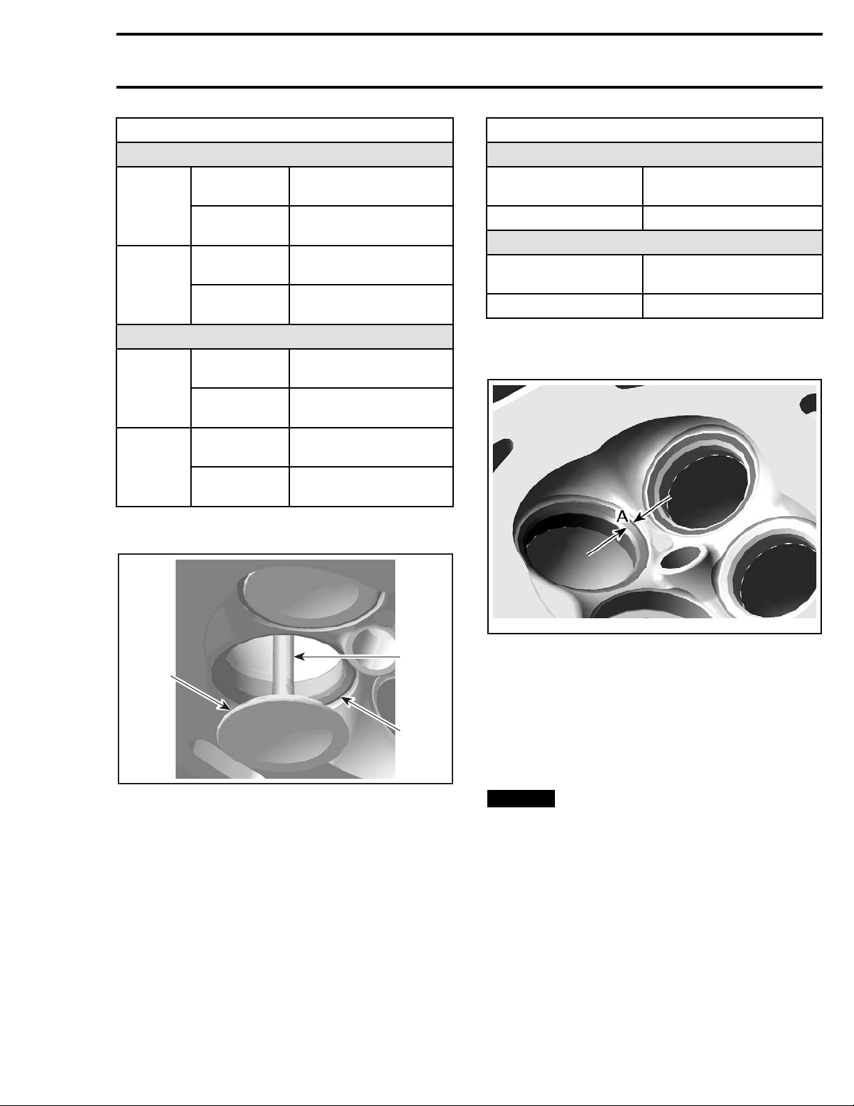
ETER
4.956 mm to 4.970 mm
(.1951 in to .1957 in)
4.930 mm (.1941 in)
5.461 mm to 5.476 mm
(.215into.2156in)
5.440 mm (.2142 in)
4.966 mm to 4
(.1955 in to .1961 in)
4.930 mm (.1941 in)
5.472 mm to 5.486 mm
(.2154 in to .216 in)
5.450 mm (.2146 in)
570
engine
850 and
1000R
engines
570
engine
850 and
1000R
engines
VALVE STE M DIAM
EXHAUST VALVE
NEW
SERVICE
LIMIT
NEW
SERVICE
LIMIT
INTAKE VALVE
NEW
SERVICE
LIMIT
NEW
SERVICE
LIMIT
Inspecting the Valve Face and Seat
.980 mm
VALVESEATCONT
NEW
SERVICE LIMIT
NEW
SERVICE LIMIT
If valve sea
spots, repl
ACT WIDTH
EXHAUST VALVE
1.25 mm to 1.55 mm
(.049 in to .061 in)
2.00 mm (.079 in)
INTAKE VALVE
1.05 mm to 1.35 mm
(.041 in to .053 in)
1.80 mm (.071 in)
t contact width is too wide or has dark
ace the cylinder head.
2
3
1
R400motr84A
1. Valve seat
2. Exhau
3. Valve face (contact surface to valve seat)
st valve contaminated area
Check valve face and seat for burning or pitting
and replace valve or cylinder head if there are
signs of damage.
Ensure to seat valves properly. Apply some lapping compound to valve face and work valve on
its seat with a lapping tool (see
VALVE GUIDES
in
this subsection).
ure valve face contact width.
Meas
NOTE: The location of contact area should be in
center of valve seat.
Measure valve seat width using a caliper.
vmr2016-033-003_a
A. Valve seat contact width
Installing the Valve
Reverse the removal procedure. Pay attention to
the following details.
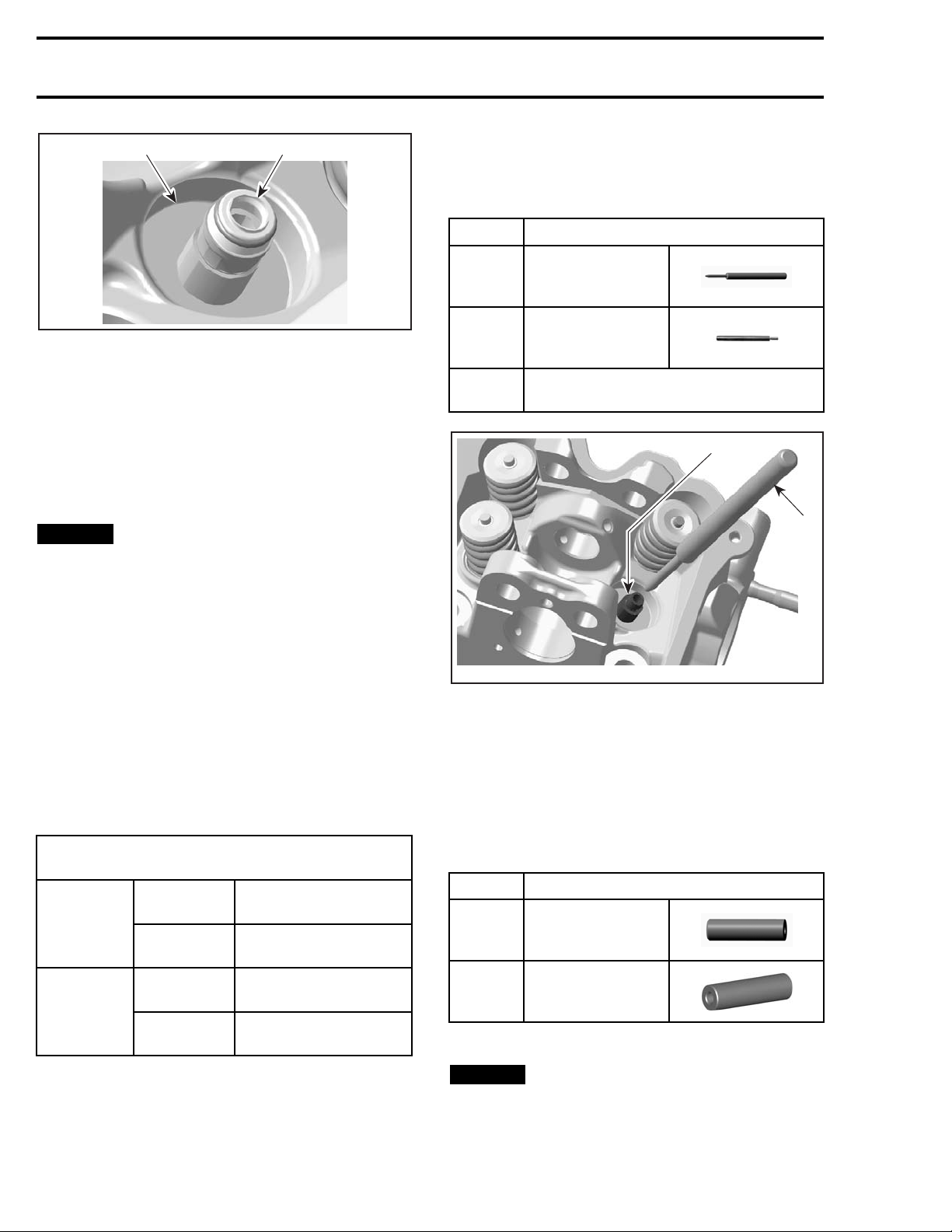
Install a NEW valve stem seal. Make sure thrust
washer is installed before installing seal.
Apply engine oil on valve stem and install it.
NOTICE
passed through sealing lips of valve stem
seal.
Be careful when valve stem is
vmr2016-419 17
Page 18
Subsection 08 (TOP END)
1
R400motr85A
1. Thrust washer
2. Sealing lips of valve stem seal
2
To ease installation of cotters, apply oil or grease
on them so that they remain in place while releasing the spring.
After spring is installed, ensure it is properly
locked by tapping on valve stem end with a soft
hammer so that valve opens and closes a few
times.
NOTICE
An improperly locked valve spring
will cause engine damage.
NOTE: Clean valve guide area from contamination
before removal.
3. Drive valve guide out of cylinder head using
specified tool.
ENGINE REQUIRED TOOL
570
engine
850 and
1000R
engines
All
engines
VALVE GU I D E
REMOVER 5 MM
(P/N 529 035 924)
VALVE GU I D E
REMOVER (6 MM)
(P/N 529 036 0
74)
Hammer
2
1
VALVE GU ID ES
Inspecting the Valve Guide
Always replace valve stem seals whenever valve
guides are removed.
Measure valve guide in three places using a small
bore gauge.
NOTE: Clean valve guide to remove carbon deposits before measuring.
Replace valve guide if it is out of specification or
has other damages such as wear or friction surface.
VALVE GUI
570
ENGINE
850 AND
1000R
ENGINE
S
DE DIAMETER (INTAKE AND
EXHAUST VALVES)
NEW
SERVICE
LIMIT
NEW
SERVIC
LIMIT
4.998 mm
(.1968 in to .1976 in)
5.050 mm (.1988 in)
5.506 mm to 5.518 mm
(.2168 in to .2172 in)
E
5.568 mm (.2192 in)
to 5.018 mm
R400motr86A
1. Valve gu
2. Valve guide
ide remover
Installing the Valve Guide
For installation, reverse the removal procedure.
Pay attention to the following details.
Clean th
valve gu
Install valve guide.
ENGINE REQUIRED TOOL
engine
850 and
1000R
engines
850 and 1000R Engines
e valve guide bore before reinstalling the
ide into cylinder head.
570
VALVE GUIDE
INSTALLER
(P/N 529 036 140)
VALVE GUIDE
INSTALLER
(P/N 529 036 269)
Remov
ing the Valve Guide
1. Remove cylinder head (see
HEAD
2. Remove valves (see
in this subsection).
VALVES
in this subsec-
CYLINDER
NOTICE
take and exhaust valve guides. Choose proper
side for installation.
Valve guide installer is used for in-
tion).
18 vmr2016-419
Page 19
Subsection 08 (TOP END)
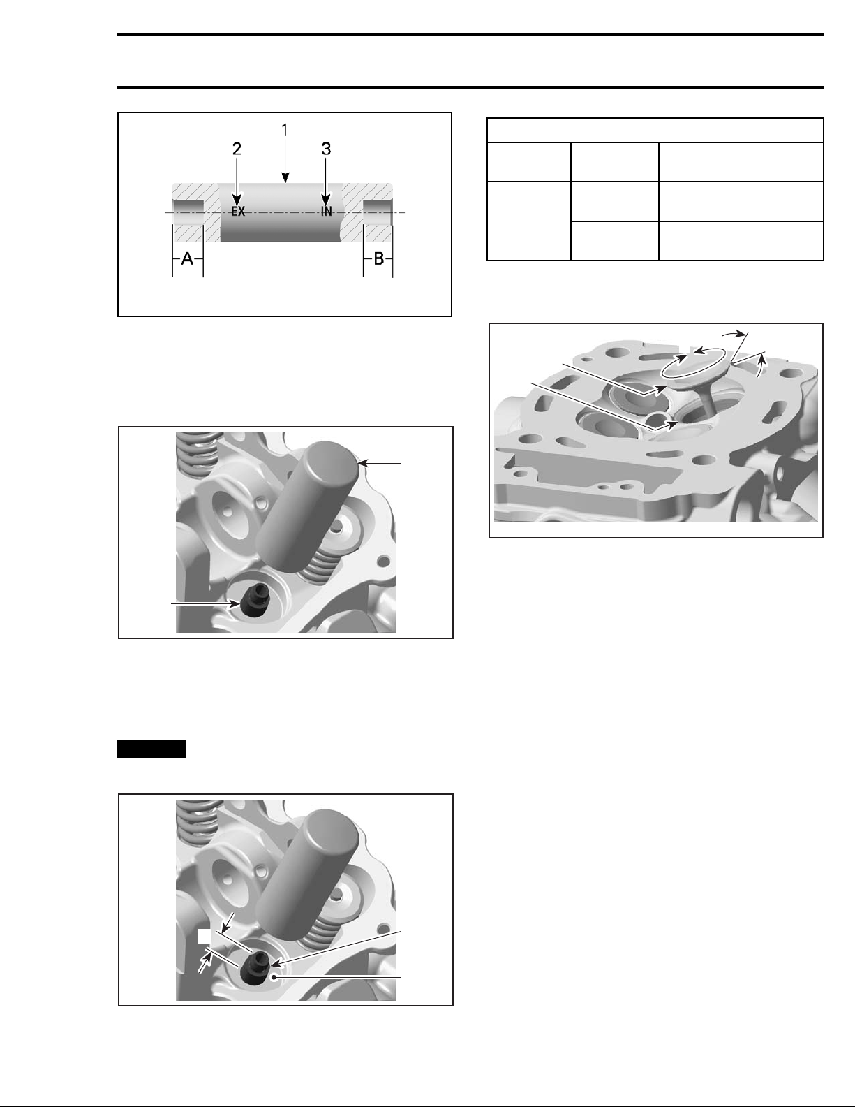
tmr2013-068-026_a
1. Valve guide installer
2. Mark "EX" - exhaust valve guide installer
3. Mark "IN" - intake valve guide installer
A. 14.5 mm (.571 in)
B. 13.3 mm (.524 in)
All Engines
1
2
R400motr87A
1. Valve guide installer
2. Valve g
uide
NOTE: Apply LOCTITE 767 (ANTISEIZE LUBRICANT)
(P/N 293 800 070)
on valve guide prior to install it
into the cylinder head.
NOTICE
Push valve guide in the cold cylinder
head as per following illustration.
VALVE GUIDE (ME
570
ENGINE
850 AND
INTAKE and
EXHAUST
INTAKE
ASUREMENT A)
14.00 mm to 14.40 mm
(.5512into.5
669 in)
13.1 mm to 13.5 mm
(.5157into.
5315 in)
1000R
ENGINES
EXHAUST
14.3 mm to 14.7 mm
(.563into.5
79 in)
Apply some lapping compound to valve face and
work valve on its seat with a lapping tool.
3
2
1
R400motr89A
1. Valve seat
2. Valve face (contact surface to valve seat)
3. Turn valve while pushing against cylinder head
A. Valve seat angle 45°
A
NOTE: Ensure to seat valves properly. Apply
marking paste to ease checking contact pattern.
Repeat procedure until valve seat/valve face fits
together.
CYLINDER
Removing the Cylinder
1. Refer to the
move the following parts:
– Chain tensioner
– Camshaft timing gear.
2. Remove the cylinder head (see
HEAD
in this subsection).
3. Pull cylinder.
4. Discard cylinder base gaskets.
TIMING CHAIN
subsection to re-
CYLINDER
A
2
1
R400motr87B
1. Thrust surface o f cylinder head
2. Valve guide
surement from thrust surface to valve guide top
A. Mea
vmr2016-419 19
Page 20
Subsection 08 (TOP END)
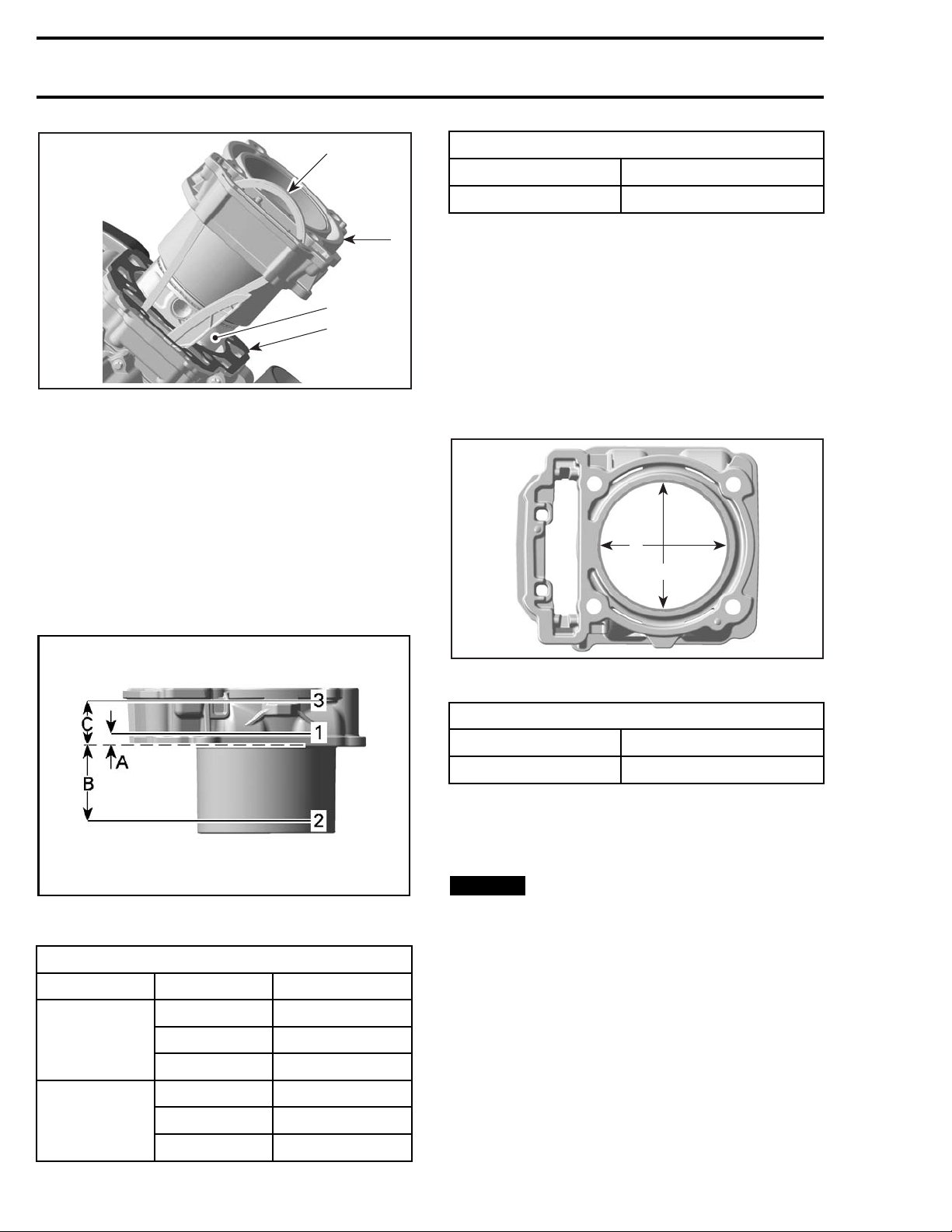
4
1
2
3
R400motr90A
1. Cylinder
2. Piston assembly
3. Cylinder base gasket
4. Camshaft timing chain
Inspecting the Cylinder
Check cylinder for cracks, scoring and wear ridges
on the top and bottom of the cylinder. If so, replace cylinder.
Cylinder Taper
Measure cylinder bore at recommended positions.
CYLINDER TAPER
NEW (MAXIMUM)
SERVICE LIMIT
SPECIFICATION
0.038 mm (.0015 in)
0.090 mm (.0035 in)
Distance between measurements should not exceed the s ervice limit. Otherwise, replace cylinder and piston rings.
Cylinder Out of Round
Measure cyli
nder diameter:
– inpistonaxis
– perpendicular to piston axis.
NOTE: Use the same measuring points as described in
CYLINDER TAPER
B
.
A
vmr2016-118-001_a
A. First measurement
B. Second
C. Third measurement
measurement
CYLINDER TAPER MEASUREMENTS
ENGINE MEASUREMENTSPECIFICATION
A 5 mm (.197 in)
570 engine
B58mm
C
A 5 mm (.197 in)
37 mm (1.46 in)
(2.28 in)
R400motr92A
A. Perpendicular to crankshaft axis
B. Parallel to crankshaft axis
CYLINDER OUT OF ROUND
NEW (MAXIMUM)
SERVICE LIMIT
0.015 mm (.0006 in)
0.020 mm (.0008 in)
Installing the Cylinder
Reverse
the foll
NOTICE
before installing the cylinder.
NOTE: Make sure piston rings are properly
spaced, refer to
section.
Apply engine oil:
– In the bottom area of the cylinder bore
–Onthep
– On the piston ring compressor.
Compre
the removal procedure. Pay attention to
owing details.
Always replace cylinder base gasket
PISTON RINGS
in this sub-
iston rings
ss piston rings.
1000R engine
20 vmr2016-419
B53mm
C
57 mm (2.24 in)
(2.09 in)
Page 21
Subsection 08 (TOP END)
REQUIRED TOOL
Piston ring compressorwithbandwidthof
15 mm to 20 mm (.
59 in to .79 in)
First mount cylinder 2.
NOTE: The cyli
thepistonun
Then remove the
(P/N 529 035 617)
nder can not be pushed fully over
less the piston is located at TDC.
CRANKSHAFT LOCKING BOLT
.
Crank the engine further and position piston 1 at
TDC.
Mount cylind
er 1.
Put timing chain through the chain passage, then
slide cylinder over piston.
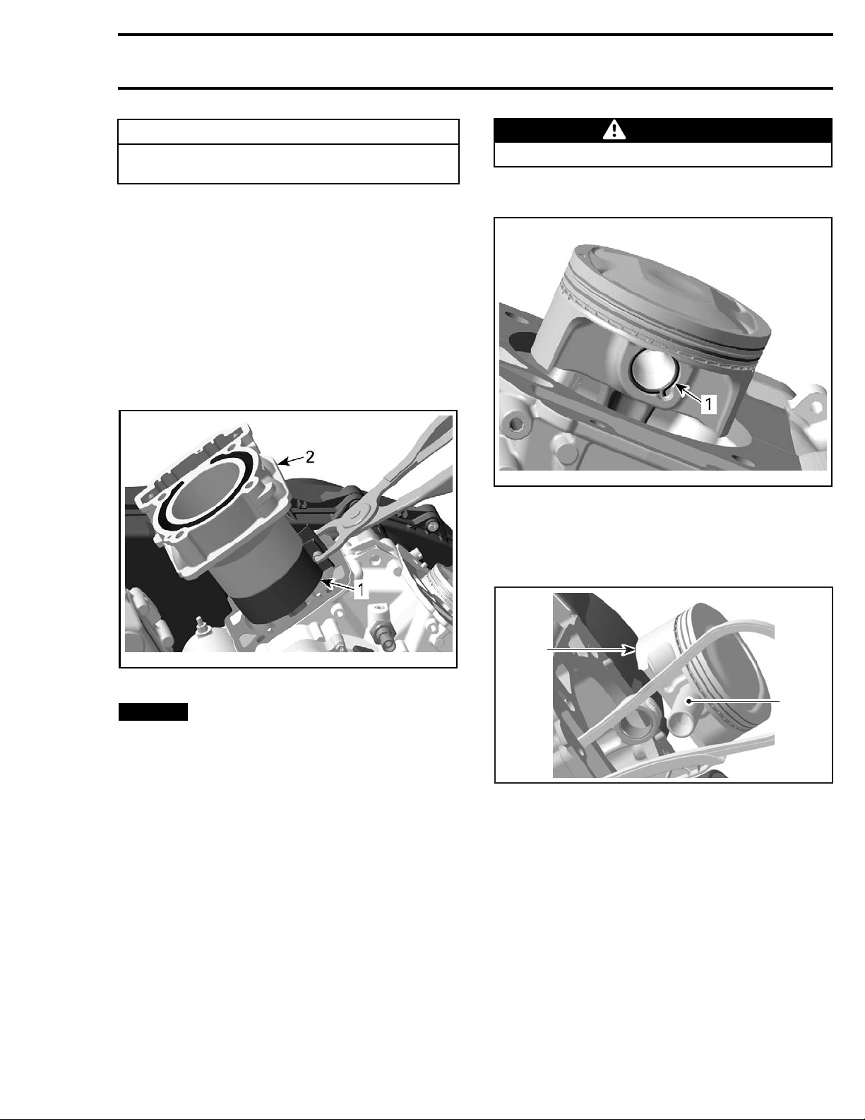
WARNING
Piston circlips are spring loaded.
3. Remove one pis
vmr2016-033-005_a
1. Piston circlip
NOTE: The removal of both piston circlips is not
necessary to remove piston pin.
4. Push piston pin out of piston.
ton circlip and discard it.
vmr2016-033-004_a
1. Piston ring compressor
2. Cylinder
NOTICE
Chain guide has to be fixed between
cylinder and cylinder head.
NOTE: After both cylinders are installed, turn
crankshaft until piston of cylinder 2 is at TDC and
lock crankshaft. Refer to
BOTTOM END
subsection.
CRANKSHAFT
in the
Install cylinder head and the other parts in accordance with the proper installation procedures.
PISTON
Removing the Piston
1. Refer to following procedures in this subsection
and remove following parts:
– Cylinder head
– Cylinder.
2. Place a rag under piston and in the area of timing chain compartment.
1
2
R400motr95A
on
1. Pist
2. Piston pin
5. Detach piston from connecting rod.
ecting the Piston
Insp
Inspect piston for scoring, cracking or other damages. Replace piston and piston rings if necessary.
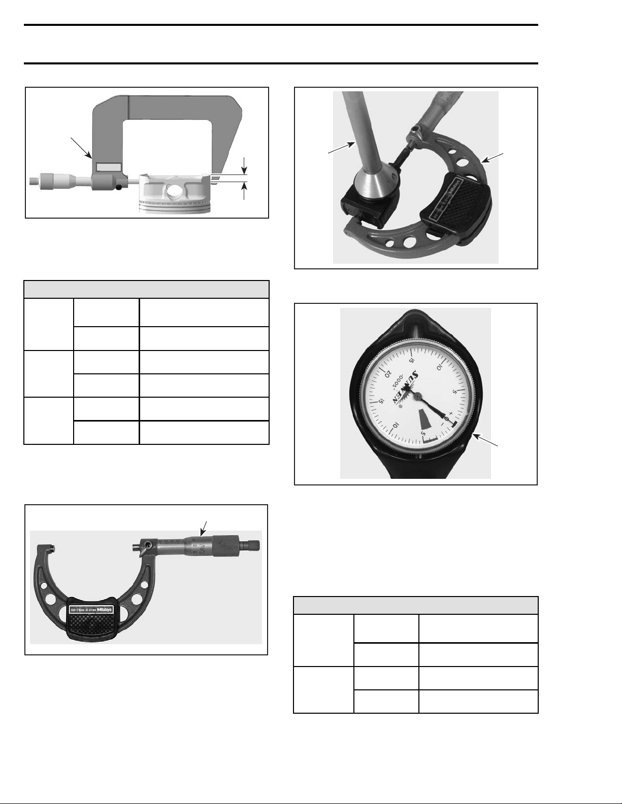
Using a micrometer, measure piston at 8 mm
(.315 in) perpendicularly (90°) to piston pin.
vmr2016-419 21
Page 22
Subsection 08 (TOP END)
1
R400motr96A
1. Measuring perpendicularly (90°) to piston pin
A. 8 mm (.315 in)
A
The measured dimension should be as described
in the following tables. If not, replace piston.
SUREMENT
83.950 mm to 83.966 mm
(3.3051 in
to 3.3057 in)
83.850 mm (3.3012 in)
93.950 mm to 93.966 mm
(3.6988 in to 3.6994 in)
93.900 mm (3.6969 in)
90.950 mm to 90.966 mm
(3.5807 in to 3.5813 in)
90.900 mm (3.5787 in)
570
ENGINE
850
ENGINE
1000R
ENGINE
PISTON MEA
NEW
SERVICE
LIMIT
NEW
SERVICE
LIMIT
NEW
SERVICE
LIMIT
Piston/Cylinder Clearance
Adjust and lock a micrometer to the piston dimension.
1
2
F00B09A
1. Use the micrometer to set the cylinder bore gauge
2. Dial bore gauge
1
1
F00B0AA
TYPICAL
1. Indicator set to 0 (zero)
Position the dial bore gauge 20 mm (.787 in) above
cylinder base, measuring perpendicularly (90°) to
piston pin axis.
Read the measurement on the cylinder bore
gauge. The result is the exact piston/cylinder wall
clearance.
N/CYLINDER CLEARANCE
PISTO
0.057 mm to 0.087 mm
22 in to .0034 in)
(.00
0.130 mm (.0051 in)
0.027 mm to 0.057 mm
(.0011 in to .0022 in)
0.100 mm (.0039 in)
F00B08A
1. Micrometer set to the piston dimension
With the micrometer set to the dimension, adjust
a cylinder bore gauge to the micrometer dimension and set the indicator to 0 (zero).
570
ENGINE
850 AND
1000R
ENGINES
NEW
SERVICE
T
LIMI
NEW
SERVICE
IT
LIM
NOTE: Make sure used piston is not worn.
22 vmr2016-419
Page 23
If clearance exceeds specified tolerance, replace
piston by a new one and measure piston/cylinder
clearance again.
NOTE: Make sure the cylinder bore gauge indicator is set exactly at the same position as with the
micrometer, otherwise the reading will be false.
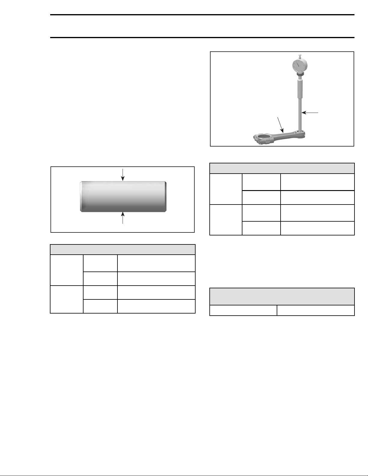
Connecting Rod/Piston Pin Clearance
Using synthetic abrasive woven, clean piston pin
from deposits.
Inspect piston pin for scoring, cracking or other
damages.
Measure piston pin. See the following illustration
for the proper measurement positions.
Subsection 08 (TOP END)
2
R1004motr11A
1. Bore gauge
2. Connecting rod
CONNECTING ROD SMALL END DIAMETER
1
R400motr30A
A. Piston pin
570
AND 850
ENGINES
1000R
ENGINE
Replace
diameter
PISTON PIN D IAMETER
NEW
SERVICE
LIMIT
NEW
SERVICE
LIMIT
piston pin if diameter is out of specifica-
A
19.996 mm to 20.000 mm
(.7872 in to .7874 in)
19.980 mm (.7866 in)
21.996 mm to 22.000 mm
(.866into.866in)
21.980 mm (.8654 in)
tions.
Measure inside diameter of connecting rod small
end bushing.
570
AND 850
ENGINES
1000R
ENGINE
Replace
rod smal
BOTTOM
NEW
SERVICE
LIMIT
NEW
SERVICE
LIMIT
connecting rod if diameter of connecting
l end is out of specifications. Refer to
END
subsection for removal proce-
20.010 mm to 20.020 mm
(.7878 in to .7882 in)
20.060 mm (.7898 in)
22.010 mm to 22.020 mm
(.8665 in to .8669 in)
22.050 mm (.8681 in)
dure.
Compare measurements to obtain the connecting
rod/piston pin clearance.
CONNECTING ROD/
PISTON PIN CLEARANCE
SERVIC
ELIMIT
0.080 mm (.0031 in)
Installing the Piston
Reverse the removal procedure. Pay attention to
the following details.
Apply
Insert piston pin into piston and connecting rod.
engine oil on the piston pin.
570, 850 and 1000R Engines
For ea
arrow
side o
ch cylinder, install piston with the punched
on piston dome pointing towards the rear
f the engine.
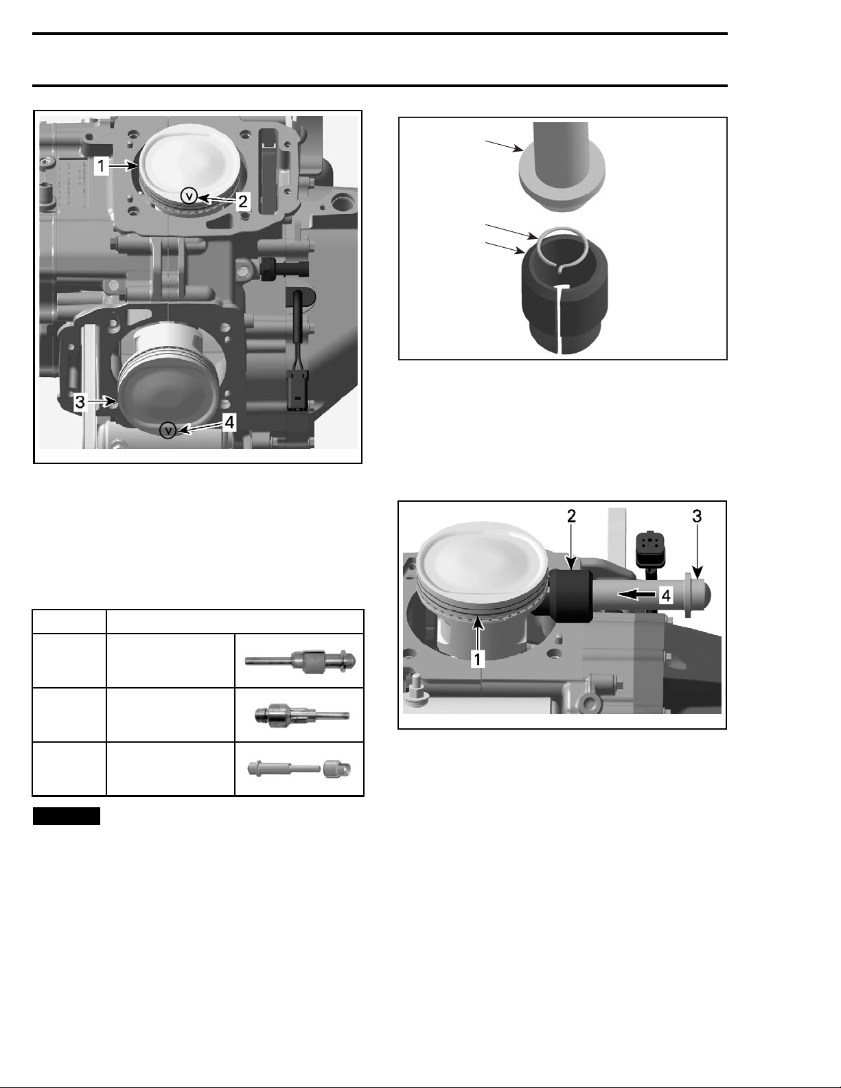
Front cylinder: Mark on top of piston must show
to intake side.
Rear cylinder: Mark on top of piston must show
to exhaust side.
vmr2016-419 23
Page 24
Subsection 08 (TOP END)
vmr2016-118-002_a
570 , 850 AND 1 000R ENGINES
1. Piston of cylinder 1 (front)
2. Mark on piston must show to intake side of cylinder 1
3. Piston of cylinder 2 (rear)
4. Mark on piston must show to exhaust side of cylinder 2
3
1
2
R400motr100A
1. Circlip
2. Sleeve
3. Assembly jig from piston clip installer
Push taper side of assembly jig until circlip
reaches middle of sleeve.
Alignsleevewithpistonpinaxisandpushassembly jig until circlip engages in piston.
All Engines
Use the piston appropriate circlip installer to assemble the NEW piston circlip as per following
procedure:
ENGINE REQUIRED TOOL
PISTON CIRCLIP
570
INSTALLER
(P/N 529
035 921)
PISTON CIRCLIP
850
INSTALLER
(P/N 529 036 083)
PISTON
1000R
CIRCLIP
INSTALLER
(P/N 529 036 153)
NOTICE
Always replace disassembled piston
circlip(s) by NEW ones. Place a rag on cylinder
base to avoid dropping the circlip inside the engine.
Place circlip in sleeve as per following illustration.
7-036-008_a
vmr200
1. Hold piston while pushing circlip in place
2. Sleeve
3. Assem
4. Direction to push circlip
bly jig
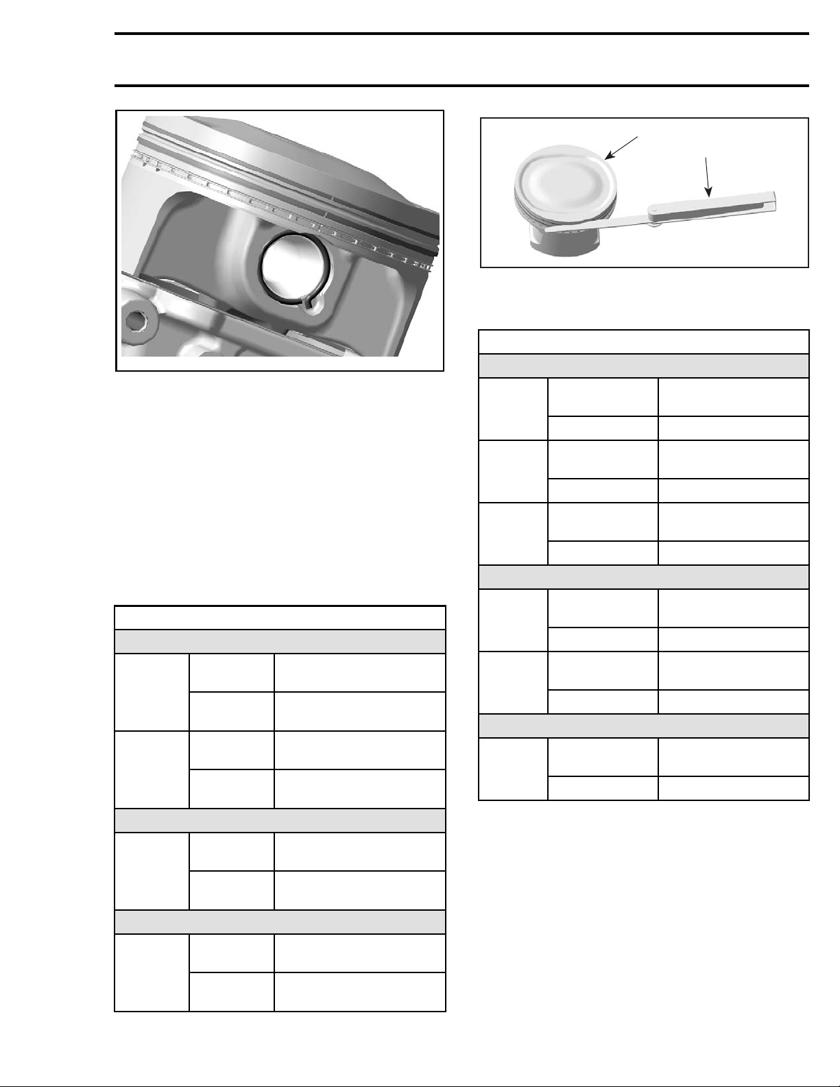
NOTE: Take care that the hook of the piston circlip
is positioned properly.
24 vmr2016-419
Page 25
vmr2016-033-006
CORRECT POSITION OF THE PISTON CIRCLIP
PISTON RINGS
Removing the Piston Rings
Removethepiston(see
tion).
Inspecting the Piston Rings
Ring/Piston Groove Clearance
Using a fee
groove cle
piston and
570
engine
850 and
1000R
engines
All
engines
All
engines
ler gauge measure each ring/piston
arance. If the clearance is too large, the
the piston rings should be replaced.
RING/PISTON GROOVE CLEARANCE
UPPER COM
NEW
SERVICE
LIMIT
NEW
SERVICE
LIMIT
LOWER COMPRESSION RING
NEW
SERVICE
LIMIT
OIL SCRAPER RING
NEW
CE
SERVI
LIMIT
PISTON
PRESSION RING
0.025 mm to 0.070 mm
(.001 in t
0.100 mm (.0039 in)
0.030 mm to 0.070 mm
(.0012 in to .0028 in)
0.150 mm (.0059 in)
0.020 mm to 0.060 mm
(.0008 in to .0024 in)
0.150 mm (.0059 in)
0.010 mm to 0.180 mm
(.0004 in to .0071 in)
0.250 mm (.0098 in)
in this subsec-
o .0028 in)
Subsection 08 (TOP END)
1
2
R400motr103A
1. Piston
2. Feeler gauge
Ring End Gap
RING END GAP
UPPER COMPRESSION RING
570
engine
850
engine
1000R
engine
570
and 850
engine
1000R
engine
All
engines
NEW
SERVICE LIMIT
NEW
SERVICE LIMIT
NEW
SERVICE LIMIT
LOWER COMPRESSION RING
NEW
s
SERVICE
SERVICE LIMIT
SERVICE LIMIT
LIMIT
NEW
OIL SCRAPER RING
NEW
0.10 mm to 0.30 mm
(.004 in to .012 in)
0.50 mm (.02 in)
0.20 mm to 0
(.008 in to .014 in)
0.60 mm (.024 in)
0.20 mm to 0.40 mm
(.008 in to .016 in)
0.60 mm (.024 in)
0.35 mm to 0.55 mm
(.014 in to .022 in)
0.85 mm (.033 in)
0.20 mm to 0.40 mm
(.008 i
0.70 mm (.028 in)
0.20 m
(.008 in to .028 in)
1.00 mm (.039 in)
.35 mm
nto.016in)
mto0.70mm
To measure the ring end gap p lace the ring
in the cylinder in the area of 8 mm to 16 mm
(5/16 in to 5/8 in) from top of cylinder.
NOTE: In order to correctly position the ring in the
cylinder, use piston as a pusher.
Using a feeler gauge, check ring end gap. Replace
ring if gap exceeds specified tolerance.
Installing the Piston Rings
For installation, reverse the removal procedure.
Pay attention to the following details.
NOTE: First install spring and then rings of oil
scraper ring.
vmr2016-419 25
Page 26
Subsection 08 (TOP END)
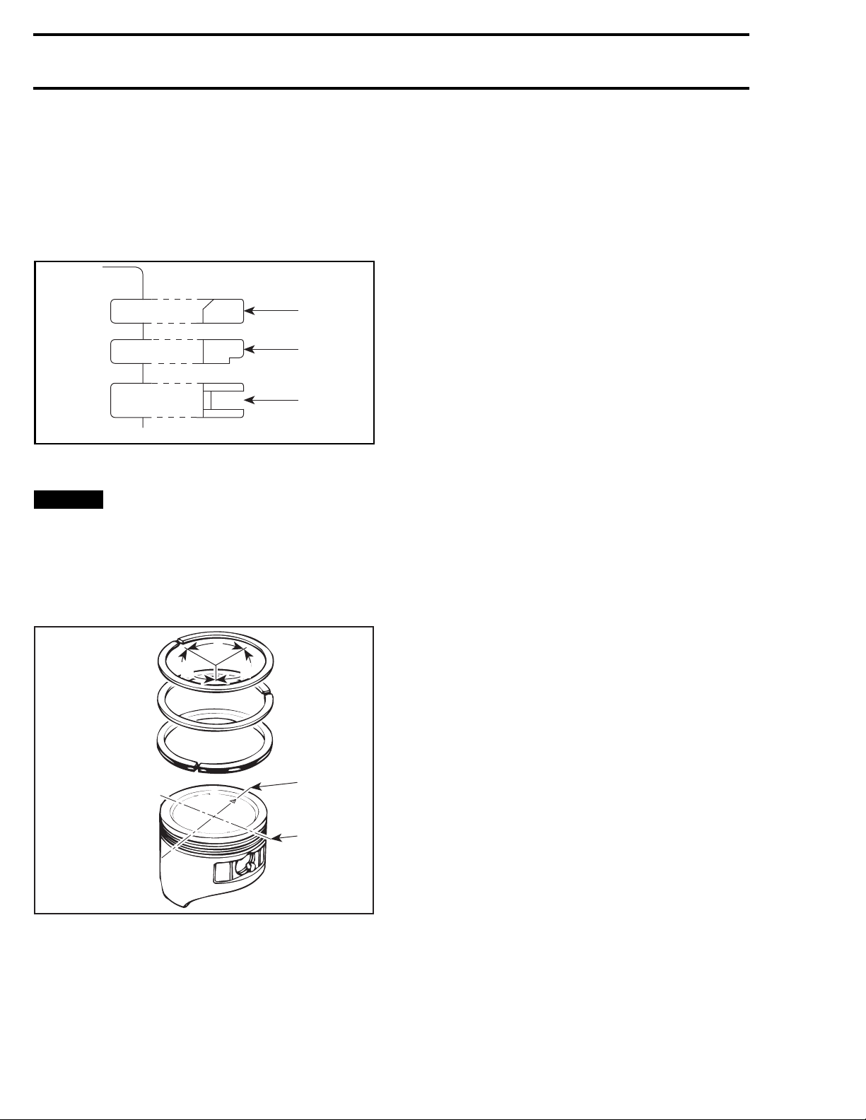
NOTE: Use a ring expander to prevent breakage
during installation. The oil ring must be installed
by hand.
Install the oil scraper ring first, then the lower
compressionringwiththeword“NandTOP“
facing up, then the upper compression ring with
the word “N a nd TOP“ facing up.
1
2
3
vmr2007-036-009_a
1. Upper compression ring
2. Lower compression ring
3. Oil scraper ring
NOTICE
Ensure that top and second rings are
not interchanged.
Check that rings rotate smoothly after installation.
Space the piston ring end gaps 120° apart and do
not align the gaps with the piston pin bore or the
thrust side axis.
A
A
A31C2OA
1. DO NOT align ring gap with piston thrust side axis
2. DO NO
A. 120°
T align ring gap with piston pin bore axis
A
1
2
26
vmr2016-419
 Loading...