

Page 1
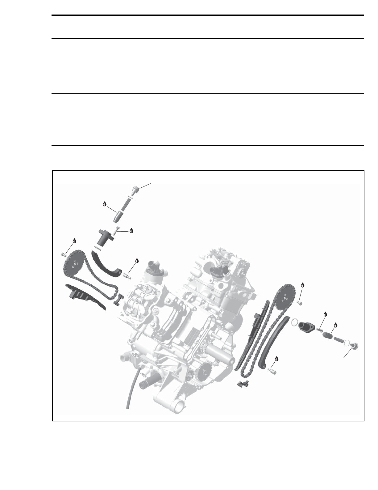
Subsection 09 (TIMING CHAIN)
TIMING CHAIN
SERVICE TOOLS
Description Part Number Page
CAMSHAFT TIMING TOOL........................................................... 529 036 268 ............................................. 5
CRANKSHAFT TDC POSITION TOOL ........................................... 529 036 201 ......................................... 5, 9
SERVICE PRODUCTS
Description Part Number Page
LOCTITE 243 (BLUE)..................................................................... 293 800 060 ....................................... 6, 11
4,5 ± 0,5 N•m
(40 ± 4 lbf•in)
0,1 N•m
(0.89 lbf•in)
Engine oil
10 ± 1 N•m
(89 ± 9 lbf•in)
Loctite 243
6 ± 0,7 N•m
6 ± 0,7 N•m
(53 ± 6 lbf•in)
(53 ± 6 lbf•in)
Loctite 243
Loctite 243
10 ± 1 N•m
(89 ± 9 lbf•in)
Loctite 243
10 ± 1 N•m
(89 ± 9 lbf•in)
Loctite 243
10 ± 1 N•m
(89 ± 9 lbf•in)
Loctite 243
6 ± 0,7 N•m
(53 ± 6 lbf•in)
Loctite 243
0,1 N•m
(0.89 lbf•in)
Engine oil
4,5 ± 0,5 N•m
(40 ± 4 lbf•in)
vmr2015-033-010_a
vmr2016-420 1
Page 2
Subsection 09 (TIMING CHAIN)
TROUBLESHOOTING
UNUSUAL ENGINE NOISE OR VIBRATION
1. IMPROPER VALVE CLEARANCE ADJUSTMENT
AND/OR WORN OUT ROCKER ARM(S)
- Readjust val
part(s), refer to TOP END subsection.
2. DEFECTIVE CHAIN TENSIONER
- Replace chai
ve clearance and/or replace defective
n tensioner.
3. WORN OUT TIM
- Replace timing chain guide(s).
4. STRETCHED TIMING CHAIN OR WORN OUT
TIMING GEARS
-Replaceti
5. LOOSE TIMI
- Retighten screws to recommended torque.
6. INCORRECT CAMSHAFT TIMING
- Replace damaged components and readjust
camshaft timing.
ENGINE LA
CKS ACCELERATION OR
ING CHAIN GUIDE(S)
ming chain and timing gears.
NG GEAR RETAINING SCREWS
POWER
1. INCORRE
- Replace damaged components and readjust
camshaf
PROCEDU
TIMING C
CT CAMSHAFT TIMING
t timing.
RES
HAIN TENSIONERS
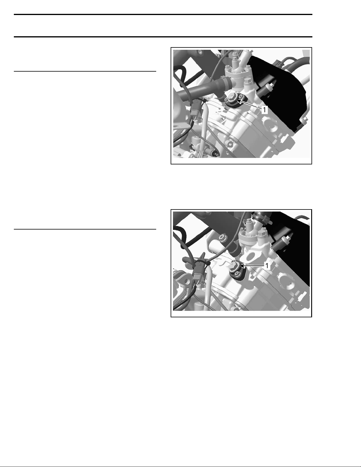
Timing Chain Tensioner Location
tmr2011-045-005_a
570 ENGINE (FRONT CYLINDER SHOWN)
1. Timing chain tensioner
850 and 1000R Engines
The timing chain tensioner is located in the cylinder.
570 Engi
The timing chain tensioner is located on the back
of each cylinder head.
ne
tmr2011-045-002_a
850 AND 1000R ENG INES (FRONT CYLINDER SHOWN)
1. Timing chain tensioner
Timing Chain Tensioner Access
For the front cylinder, the chain tensioner is accessible from the RH side.
For the rear cylinder chain tensioner, remove the
exhaust system outer heat shield. Refer to
HAUST SYSTEM
subsection.
EX-
Removing the Timing Chain Tensioner
1. Make sure the applicable piston is set to TDC ignition. Refer to
CAMSHAFT TIMING GEARS
this subsection.
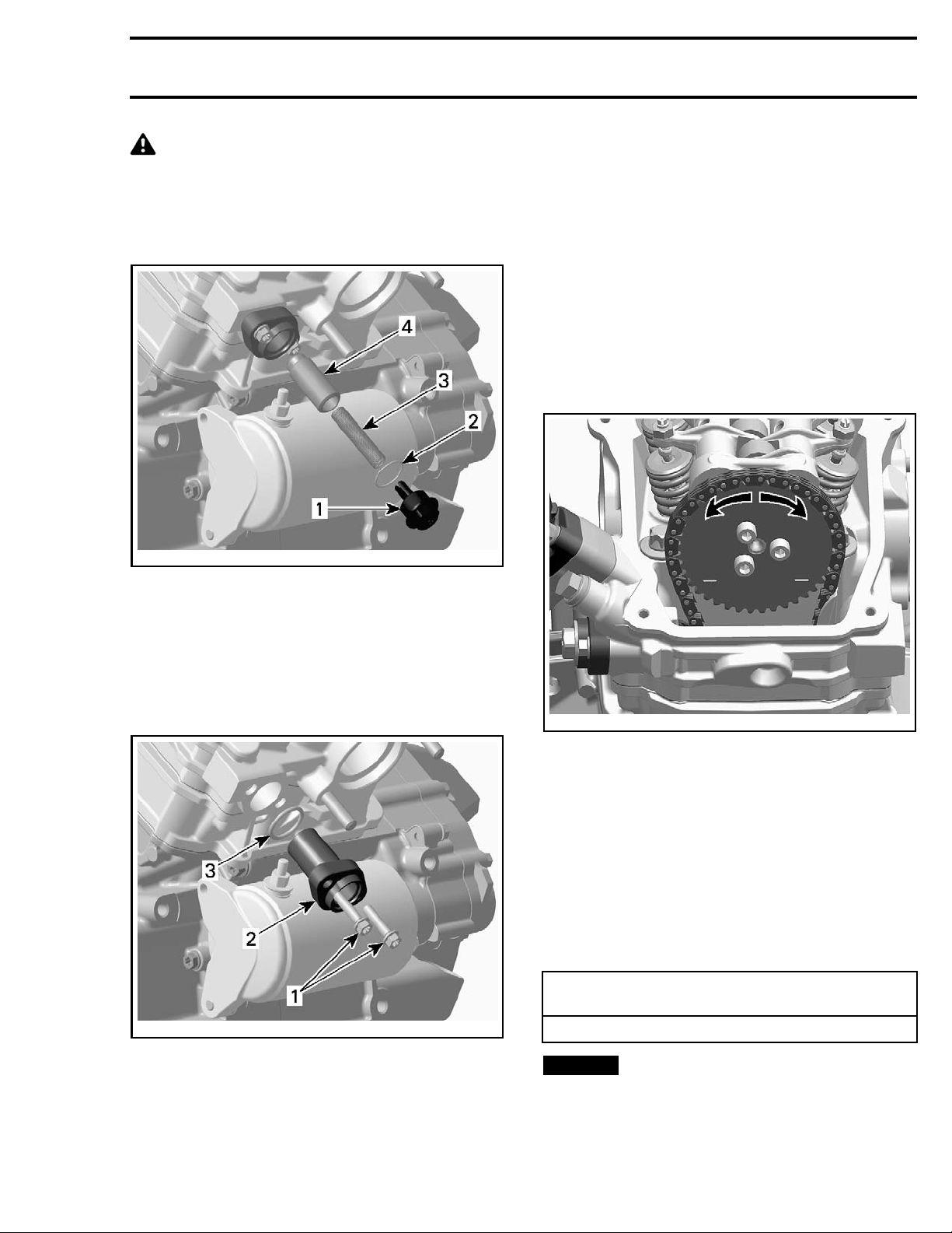
2. Carefully remove chain tensioner screw plug
and release spring tension.
2 vmr2016-420
in
Page 3
Subsection 09 (TIMING CHAIN)
CAUTION Tensioner is spring loaded.
3. Remove:
–O-ring
–Spring
– C hain tensioner plunger.
vmr2006-043-004_a
1. Chain tensioner screw plug
2. O-ring
3. Spring
4. Chain tensioner plunger
Check chain tensioner plunger for freedom of
movement and/or scoring.
Ensure O-rings are not brittle, cracked or hard. Replace if necessary.
Check spring condition. Replace if bent, broken or
worn.
Installing the Timing Chain Tensioner
Reverse the removal procedure. However, pay attention to the following.
NOTE: Before installing the chain tensioner, make
sure the camshaft timing gear can be moved back
and forth.
4. Remove:
– C hain tensioner housing retaining screws
– C hain tensioner housing
– O-ring.
vmr2006-043-005_a
1. Screws
ain tensioner housing
2. Ch
3. O-ring
Inspecting the Timing Chain Tensioner
Check chain tensioner housing and screw plug for
cracks or other damages. Replace if necessary.
tmr2011-045-003_a
MOVE GEAR
BACK AND FORTH
1. Apply engine oil on the chain tensioner plunger
before installation.
2. Slightl
y turn the camshaft timing gear in order
to move t
sioner s
he timing chain excess play to the ten-
ide.
3. Slightly screw in the plunger until the timing
chain does not allow back and forth movement
of the camshaft timing gear.
4. Screw the plunger in an additional 1/8 turn to
obtain the required specified torque.
TIMING CHAIN TENSIONER ADJUSTMENT
(TIGHTENING TORQUE)
0.1 N•m (.9 lbf•in)
NOTICE
Improper adjustment of the timing
chain will lead to severe engine damage.
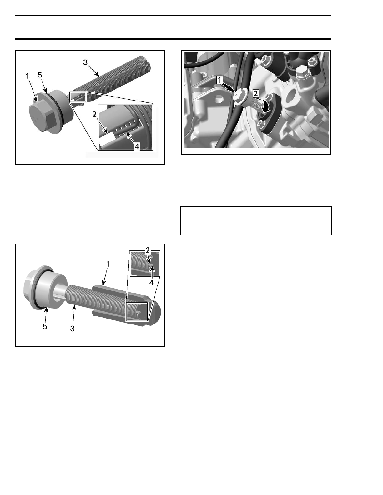
5. Place the O-ring on chain tensioner screw plug.
6. Fit the spring on one side into the slot of the
chain tensioner screw plug.
vmr2016-420 3
Page 4
Subsection 09 (TIMING CHAIN)
tmr2013-069-006_a
1. Plug
2. Slot
3. Spring
4. Spring end
5. O-Ring
7. Fit the spring on the other side into the plunger.
NOTE: Turn spring only clockwise in order to fit
the spring end into the notch of the plunger to
avoid loosening the plunger during spring installation. Do not preload the spring.
tmr2013-069-008_a
Step 1: Compress spring
Step 2: Screw in plug
9. Remove locking tool and install all other removed parts.
10. Tighten the chain tensioner screw plug to
specification.
TIGHTENING TORQUE
Chain tensioner plug
4.5 N•m ± 0
(40 lbf•in ±4lbf•in)
.5 N•m
tmr2013-069-007_a
FOR CLARITY PARTS A RE REMOVED FROM CYLINDER
1. Plung
2. Notch
3. Spring
4. Sprin
5. Plug with O-ring
er
gend
8. Then compress the spring and screw the plug
in.
NOTE: To avoid overstressed timing chain, the
plug must engage into threads within the first full
turn.
CAMSHAFT TIMING GEARS
Removin
1. Remove valve cover, refer to
tion.
2. Set applicable piston to TDC ignition and lock
magneto flywheel. Refer to
ING
3. Remove
ING CH
4. Remove camshaft timing gear retaining
screws.
g the Camshaft Timing Gear
TOP END
CAMSHAFT TIM-
in this subsection.
timing chain tensioner. Refer to
AIN TENSIONERS
in this subsection.
subsec-
TIM-
4 vmr2016-420
Page 5
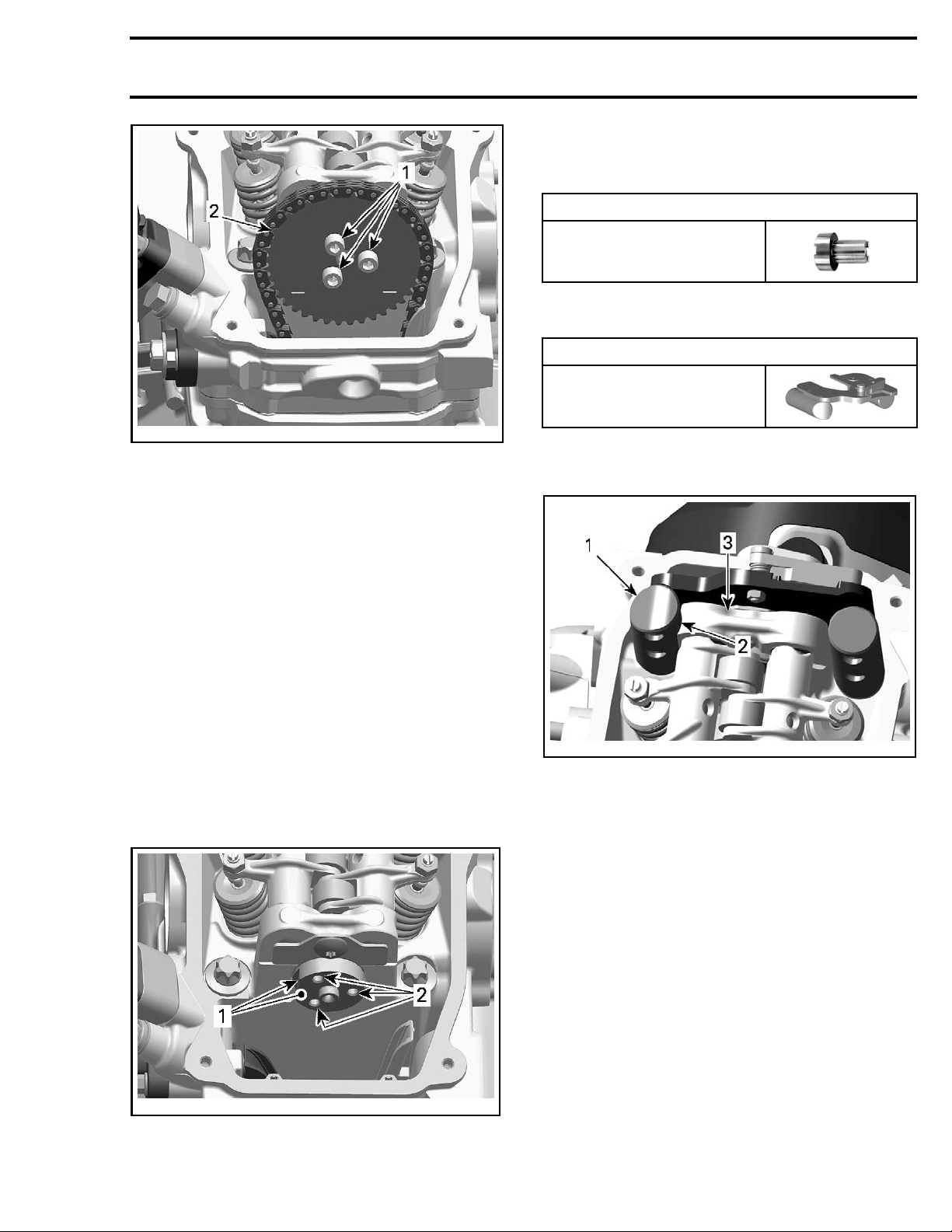
tmr2011-045-003_b
TYPICAL
1. Camshaft timing gear retaining screws
2. Camshaft timing gear
5. Remove the camshaft timing gear.
NOTE: Secure timing chain with a piece of wire.
Subsection 09 (TIMING CHAIN)
2. Set applicable piston to TDC ignition position
and install the crankshaft position tool, refer to
CAMSHAFT TIMING
REQUIRED TOOL
CRANKSHAFT TD C
POSITION TOOL
(P/N 529 036 2
3. Install camshaft timing tool on the cylinder
head.
REQUIRED TOOL
CAMSHAFT TIMING TOOL
(P/N 529 036 268)
NOTE: Properly align tube of camshaft timing tool
with machined radius on cylinder head.
in this subsection.
01)
Inspecting the Camshaft Timing Gear
Check camshaft timing gear for wear or deterioration.
If timing gear is worn or damaged, replace it as a
set with the timing chain.
For crankshaft gear inspection, refer to
SHAFT
in the
BOTTOM END
subsection.
CRANK-
Installing the Camshaft Timing Gear
For installation, reverse the removal procedure.
Pay attention to the following details.
1. Clean camshaft mating surface and threads
prior to installing camshaft timing gear.
vmr2015-033-001_a
CAMSHAFT TIMING TOOL INSTALLED
1. Tube (camshaft timing tool)
2. Machined radius (camshaft timing tool)
3. Cylinder head
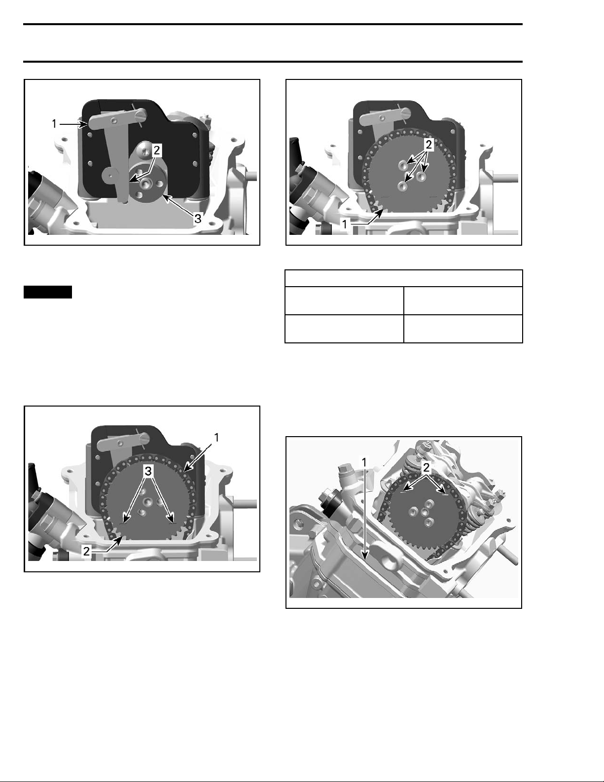
4. Set camshaft to TDC ignition position by aligning the flat portion on the camshaft flange with
the tool lever.
NOTE: In addition, to ensure proper camshaft timing, press camshaft timing tool lever downwards.
11-045-004_a
tmr20
1. Camshaft mating surface
2. Camshaft screw threads
vmr2016-420 5
Page 6
Subsection 09 (TIMING CHAIN)
vmr2015-033-002_a
PRESS TOOL LEVER DOWN
1. Lever
2. Flat portion
3. Camshaft
NOTICE
Crankshaft and camshaft must
be locked at TDC ignition position to place
camshaft timing gear and timing chain in the
proper position.
5. Place camshaft timing gear and timing chain on
the camshaft.
NOTE: The printed marks on the camshaft timing
gear must be parallel to the cylinder head base.
vmr2015-033-004_a
1. Camshaft timing gear
2. Timing gear retaining screws
TIGHTENING TORQUE
Service product
Camshaft t
iming gear
retaining screws
LOCTITE 24
(P/N 293 800 060)
10 N•m ± 1 N•m
(89 lbf•in ±9lbf•in)
3(BLUE)
8. Remove the camshaft timing tool.
Camshaft
Timing
NOTE: If a piston (cylinder 1 or 2) is set to TDC
ignition, the camshaft timing gear of the opposite
cylinder must be in the following position.
15-033-003_a
vmr20
1. Timing chain
2. Camshaft timing gear
ed marks on camshaft timing gear
3. Print
6. Install and adjust timing chain tensioner, refer to
TIMING CHAIN TENSIONER
7. Inst
all and tighten camshaft timing gear retain-
crews to specified torque.
ing s
in this subsection.
tmr2011-045-011_a
TYPICAL
1. Cylinder head base
2. Marks on timing gear of the opposite cylinder
Camshaft Timing Piston No. 2 (rear)
1. Remove spark plugs of both cylinders.
2. Remove valve covers of both cylinders.
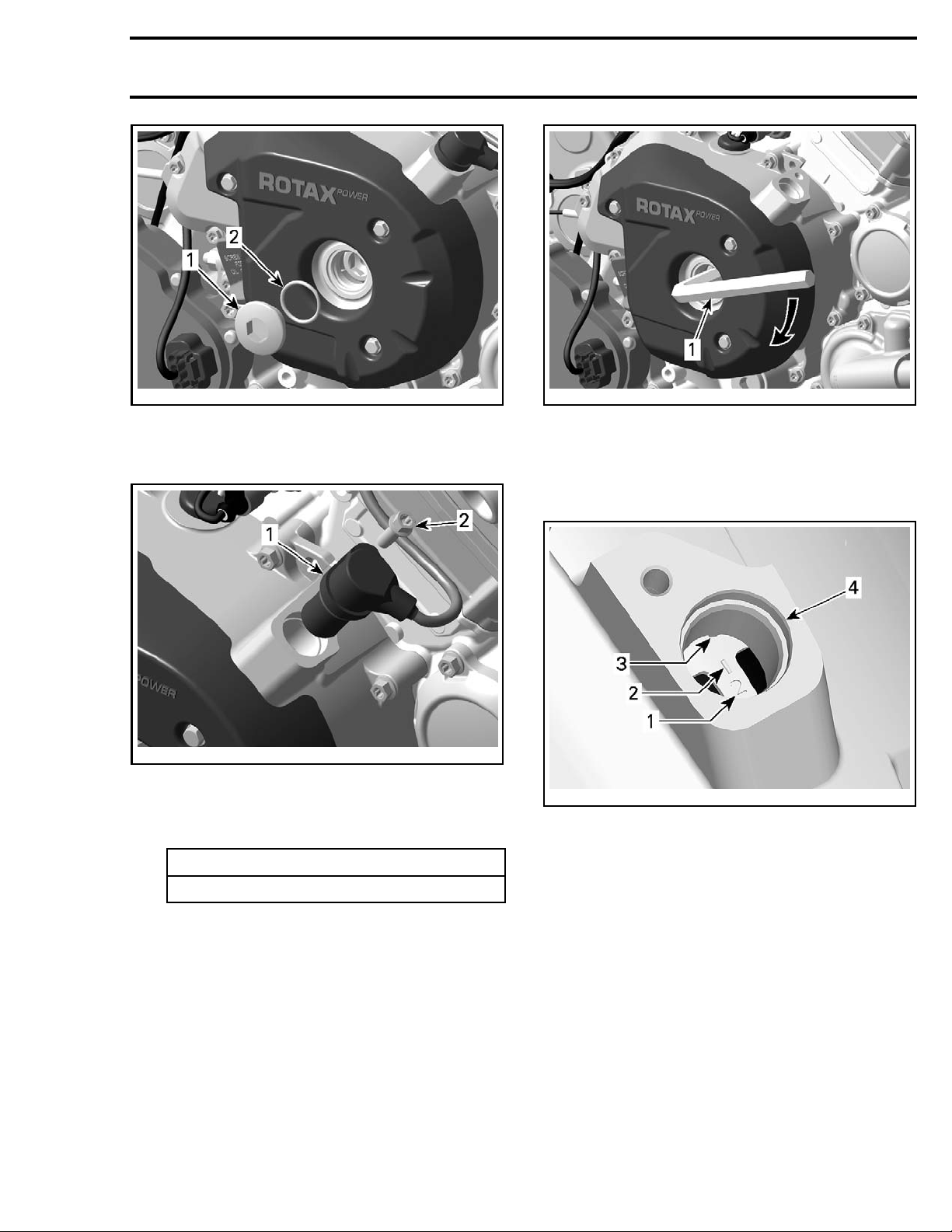
3. Remove the screw plug and O-ring from magneto cover.
6 vmr2016-420
Page 7
Subsection 09 (TIMING CHAIN)
vmr2015-033-005_a
1. Screw plug
2. O-ring
4. Remove the crankshaft position sensor (CPS).
vmr2015-033-006_a
1. CPS
2. Screw
5. Set rear piston no. 2 to TDC ignition by turning
the crankshaft clockwise.
REQUIRED TOOL
Allen key 14 mm
vmr2015-033-007_a
TURN CRANKSHAFT CLOCKWISE TO PISTON NO. 2 TDC
1. Allen key 14 mm
5.1 The rear piston is at TDC when it's index
mark on the magneto flywheel is aligned
with the notch in the magneto cover.
vmr2007-037-008_b
PISTON NO. 2 AT TDC
1. Piston
2. Index mark on magneto flywheel
3. Notch on magneto cover
4. CPS bo
no. 2 identifier
re in magneto cover
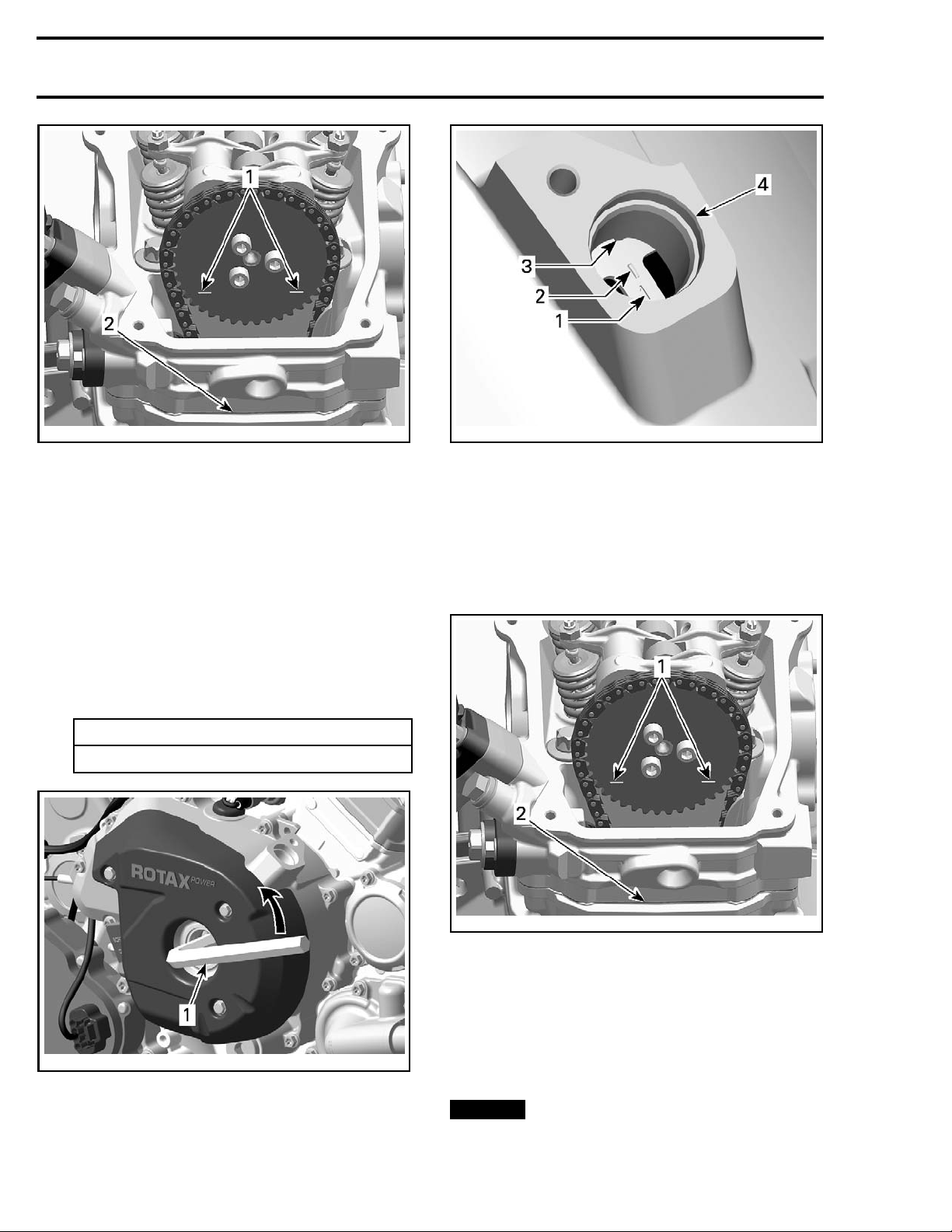
5.2 Confirm printed marks on the camshaft
timing gear are parallel with cylinder head
base, in the lowest position. In this position the piston is set to TDC ignition.
NOTE
not a
: If marks on camshaft timing gear a re
s specified, turn crankshaft 360°.
vmr2016-420 7
Page 8
Subsection 09 (TIMING CHAIN)
tmr2011-045-003_c
TYPICAL - PISTON AT TDC IGNITION
1. Printed marks on camshaft timing gear
2. Cylinder head base
6. Install the crankshaft TDC position tool to lock
crankshaft in position. Refer t o
TDC POSITION TOOL
in this subsection.
CRANKSHAFT
Camshaft Timing Piston No. 1 (front)
1. Set rear piston no. 2 to TDC ignition,see
CAMSHAFT TIMING PISTON NO. 2 (REAR)
in
this subsection.
2. Remove crankshaft TDC position tool.
3. To set front piston no. 1 to TDC ignition turn
crankshaft 280° counterclockwise.
REQUIRED TOOL
Allen k
ey 14 mm
vmr2007-036-006_b
CYLINDER 1 AT T DC
1. Number 1 piston identifier
2. Index mark “1” on magneto flywheel
3. Notch on magneto cover
4. Crankshaft position sensor bore
3.2 Confirm printed marks on the camshaft
timing gear are parallel with cylinder head
base, in the lowest position. In this position the piston is set to TDC ignition.
tmr2011-045-003_c
TYPICAL - PISTON AT TDC IGNITION
1. Printed marks on camshaft timing gear
2. Cylinder head base
4. Insert the crankshaft TDC position tool to lock
crankshaft in position. Refer to
TDC POSITION TOOL INSTALLATION
vmr2015-033-007_b
TURN COUNTERCLOCKWISE 280° TO NUMBER 1 PISTON TDC
n key 14 mm
1. Alle
3.1 The front piston is at TDC when it's index
mark on the magneto flywheel is aligned
with the notch in the magneto cover.
8 vmr2016-420
subsection.
Crankshaft TDC Position Tool Installation
NOTICE
Never use crankshaft TDC position
tool to remove or tighten drive CVT screw or
rotor retaining screw. Damage to the teeth of
the trigger wheel on the rotor will occur.
CRANKSHAFT
in this
Page 9
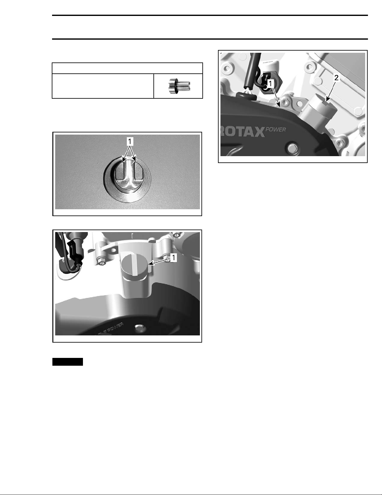
Install tool in magneto cover CPS bore.
REQUIRED TOOL
CRANKSHAFT TDC
POSITION TOOL
(P/N 529 036 20
1)
NOTE: Make sure to match the teeth on the
crankshaft TDC position tool with the magneto
rotor.
tmr2011-045-020_a
1. Crankshaft TDC position tool teeth (end view)
Subsection 09 (TIMING CHAIN)
vmr2015-033-009_a
1. Magneto cover
2. TDC position tool
TIMING CHAIN
Timing Chain Location
The engine is equipped with two timing chains.
– MAG side timing chain is located behind the
magneto cover.
– PTO side timing chain is located behind the PTO
cover.
vmr2015-033-008_a
MAGNETO COVER
1. Crankshaft TDC position tool installed in CPS bore
NOTICE
Tool must be fully inserted.
Removing the Timing Chain (MAG
Side)
1. Refer to
and remove following parts:
– Magneto cover
– Rotor
– Sprag clutch gear.
2. Refer to
following part:
– Valve cover.
3. Refer to following procedures in this subsection
and remove following parts:
– Chain tensioner
– Camshaft timing gear.
4. Remove timing chain guide (tensioner side) and
lower timing chain guide.
MAGNETO AND STARTER
TOP END
subsection and remove the
subsection
vmr2016-420 9
Page 10
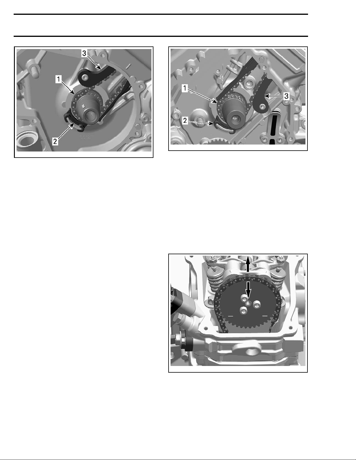
Subsection 09 (TIMING CHAIN)
Vmr2012-016-005_a
1. Timing chain
2. Lower timing chain guide
3. Timing chain guide (tensioner side)
NOTE: Mark the operating direction of the timing
chain and check for excessive radial play before
removal. Refer to
TIMING CHAIN INSPECTION
5. Carefully pull the timing chain downwards and
sideways, then out of the crankcase.
Removing the Timing Chain (PTO
Side)
1. Refer to
following parts:
–PTOcover
– Breather gear
– Intermediate gear.
2. Refer to
lowing part:
– Valve cover.
3. Refer to applicable procedures in this subsection and remove following parts:
– Chain tensioner
– C amshaft timing gear.
4. Remove timing chain guide (tensioner side) and
lower timing chain guide.
BOTTOM END
TOP END
subsection and remove fol-
subsection and remove
tmr2011-045-015_a
1. Timing chain
2. Lower timing chain guide
3. Timing chain guide (tensioner side)
NOTE: Mark the operating direction of the timing
chain and check for excessive radial play before
removal. Refer to
.
5. Carefully pull the timing chain sideward and
TIMING CHAIN INSPECTION
.
down from the crankcase.
Inspecting the Timing Chain
Inspection is the same for both timing chains.
Check timing chain on camshaft timing gear for
excessive radial play.
tmr2011-045-003_d
CHECKING TIMING CHAIN RADIAL PLAY
Check
chain condition for wear and teeth condi-
tion.
10 vmr2016-420
Page 11
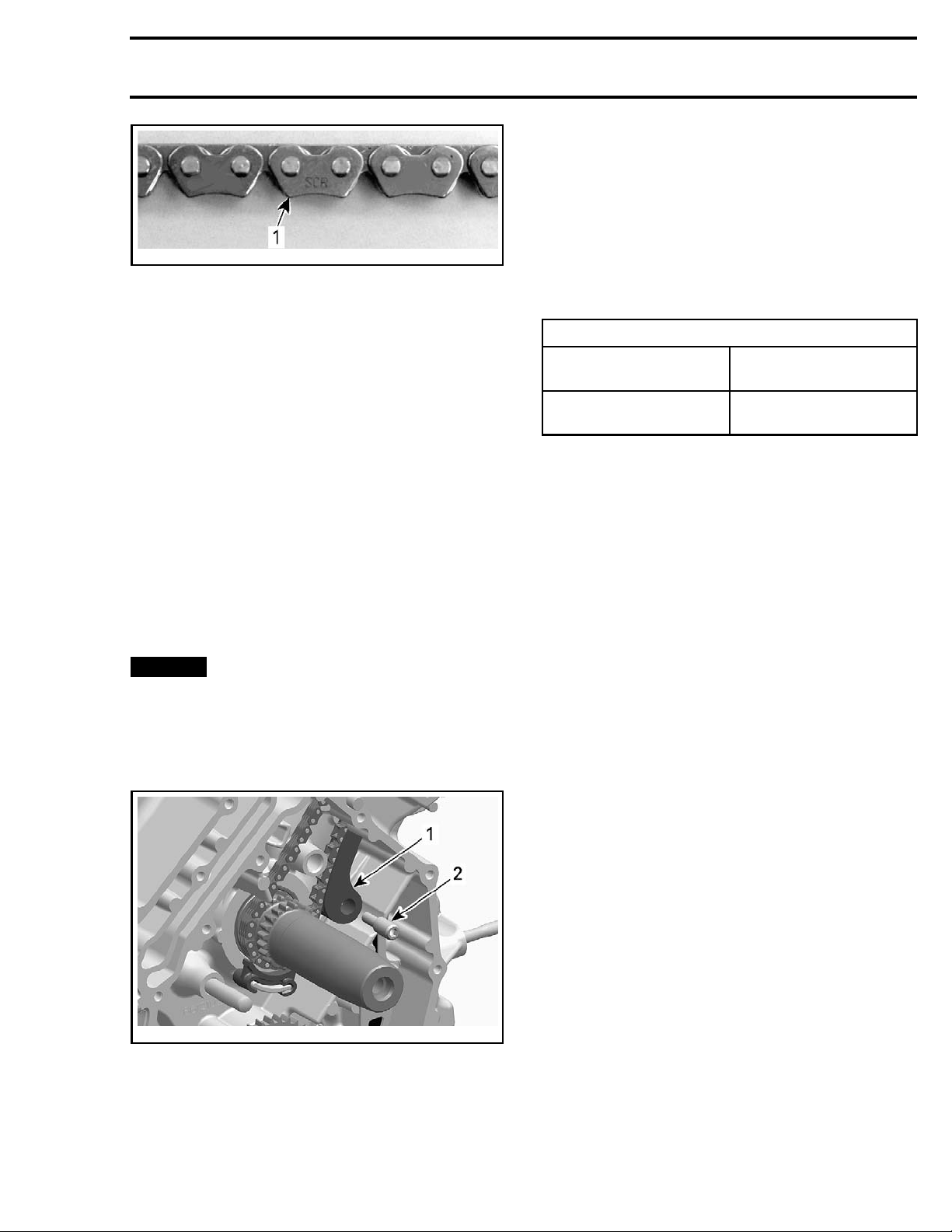
Subsection 09 (TIMING CHAIN)
Inspecting the Timing Chain Guide
(Tensioner Side)
Check timing chain guide for wear, cracks or deformation. Replace if necessary.
vmr2006-044-018_a
1. Timing chain
If chain is excessively worn or damaged, replace
it as a set (camshaft timing gear and timing chain).
Check timing chain guides for wear, cracks or deformation. Replace as required.
NOTE: Check also the timing chain guide (tensioner side).
Installing the Timing Chain
The installation is essentially the reverse of the removal procedure however, pay attention to the following details.
NOTE: Installation is the same for both timing
chains.
Install timing chain with camshaft timing gear.
NOTE: Ensure to carry out proper valve timing, re-
fer to
CAMSHAFT TIMING GEARS
tion.
NOTICE
Improper valve timing will damage
engine components.
in this subsec-
Installing the Timing Chain Guide
(Tensioner Side)
The installation is the reverse of the removal procedure.
TIGHTENING TORQUE
Service prod
Timing chain guide
bearing screw
uct
LOCTITE 243 (BLUE)
(P/N 293 800 060)
10 N•m ± 1 N•m
(89 lbf•in ±9lbf•in)
TIMING CHAIN GUIDE
(TENSIONER SIDE)
tmr2011-045-019_a
1. Timing chain guide (tensioner side)
2. Be aring screw
Removing the Timing Chain Guide
(Tensioner Side)
Refer to
TIMING CHAIN
in this subsection.
vmr2016-420 11
 Loading...