

Page 1

Subsection 01 (STEERING SYSTEM)
STEERING SYSTEM
SERVICE TOOLS
Description Part Number Page
STEERING ALIGNMENT TOOL ............................................ ......... 529 036 059 ............................................. 3
SERVICE TOOLS – OTHER SUPPLIER
Description Part Number Page
SMOOTHFLOW™ TAPERED TIP.................................................. 16 ga
#511 rtt-b
SERVICE PRODUCTS
Description Part Number Page
LOCTITE 406 (GLUE)..................................................................... 293 800 100 ............................................. 4
LOCTITE 767 ( ANTISEIZE LUBRICANT ) ....................................... 293 800 070 ............................................. 9
PULLEY FLANGE CLEANER ......................................................... 413 711 809 ............................................. 4
XPS SYNTHETIC GREASE............................................................. 293 550 010 ............................................. 9
............................................. 4
vmr2016-414 1
Page 2
Subsection 01 (STEERING SYSTEM)
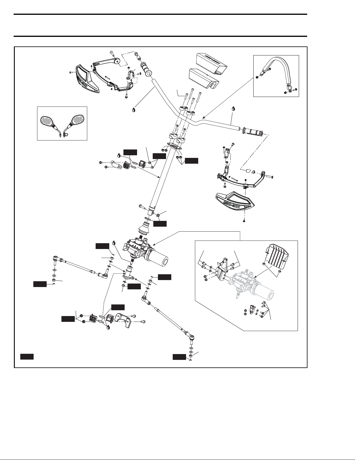
31.5 ± 3.5 N•m
(23 ± 3 lbf•ft)
X mr
Europe
NEW
72.5 ± 7.5 N•m
(53 ± 6 lbf•ft)
XPS
Synthetic
grease
Loctite 767
Antiseize
Loctite
406
24.5 ± 3.5 N•m
(18 ± 3 lbf•ft)
NEW
NEW
24.5 ± 3.5 N•m
NEW
Loctite
406
NEW
31.5 ± 3.5 N•m
(23 ± 3 lbf•ft)
(18 ± 3 lbf•ft)
24.5 ± 3.5 N•m
(18 ± 3 lbf•ft)
NEW
= Component must be replaced when removed.
NEW
vmr2016-414-100_a
72.5 ± 7.5 N•m
(53 ± 6 lbf•ft)
24.5 ± 3.5 N•m
(18 ± 3 lbf•ft)
NEW
72.5 ± 7.5 N•m
(53 ± 6 lbf•ft)
NEW
XPS
Synthetic
grease
NEW
NEW
72.5 ± 7.5 N•m
(53 ± 6 lbf•ft)
NEW
24.5 ± 3.5 N•m
(18 ± 3 lbf•ft)
24.5 ± 3.5 N•m
(18 ± 3 lbf•ft)
72.5 ± 7.5 N•m
(53 ± 6 lbf•ft)
2 vmr2016-414
Page 3
Subsection 01 (STEERING SYSTEM)
GENERAL
The procedures described below are the same for
the RH and LH sides, unless otherwise instructed.
ADJUSTMENT
STEERING ALIGNMENT
1. Place vehicle
2. Check pressure in each tire. Adjust to recommended pressure.
3. Lift and secure vehicle off the ground so that
the suspension is fully extended.
4. Remove both
cess to pitm
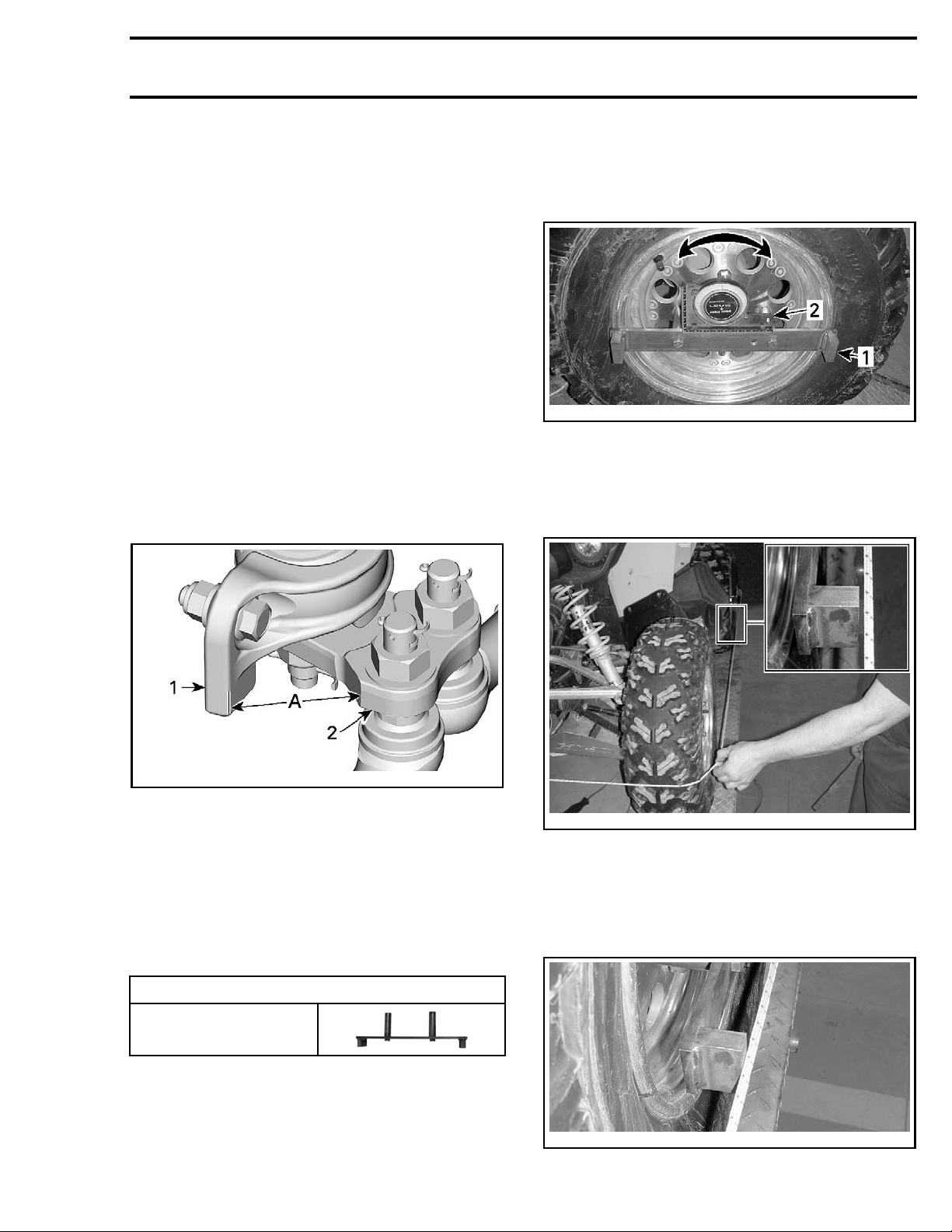
5. Center pitman arm by measuring equal distances, ±1mm, between the edges as per
the following illustration, on both sides of the
pitman arm.
on a level surface.
inner fenders to have easy ac-
an arm.
10. Rotate the front wheel to position the alignment tool level with the rope. Ensure rope
passes over the spacer blocks on the alignment tool.
8-006_a
vmr2008-06
1. Steering adjustment tool
2. Angle gauge or level
11. At the LH fr
rim, pull o
the first
ont of wheel, near the front of the
n the rope so that it does not touch
spacer block on the alignment tool.
vmr2016-059-001_a
A. Equal distance ± 1 mm (1/32 in) on both sides
1. Steeri
2. Pitman arm
6. Secure handlebar without moving steering col-
7. Make sure pitman arm remains centered. Oth-
8. Remo
9. Pla
ng column lower attach
umn.
erwise, repeat steps 5 and 6.
ve two wheel nuts on the LH rear wheel
nstall the steering alignment tool.
and i
REQUIRED TOOL
STEERING ALIGNMENT
TOOL (P/N 529 036 059)
ce a rope around all four tires using an elas-
, link both ends together.
tic
vmr2008-068-005_a
TYPICAL
12. Slowly move rope back until it just makes contact with both spacers.
NOTE: Ensure rope remains in this position as
you carry out the following steps.
NOTE: The rope must be placed at the center of
the wheels.
vmr2016-414 3
vmr2008-068-007
TYPICAL
Page 4
Subsection 01 (STEERING SYSTEM)
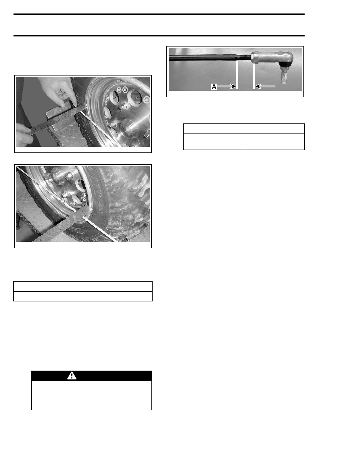
13. Measure the distance between the rope and
the rim, at the front and at the rear of the
wheel rim.
tmr2011-034-107_a
A. Maximum tie-
rod end length
15.3 Tighten tie-rod end lock nuts to specification.
TIGHTENING TORQUE
vmr2008-068-008
TYPICAL — FRONT OF WHEEL
vmr2008-068-009
TYPICAL — REAR OF W HEEL
14. Calculat
and rear
followi
e the difference between the front
measurements and compare with
ng specification.
SPECIFICATION
0mm to3m
m(0into.118in)toe-in
15. If the w heel toe measurement is out of specification, carry out the following:
15.1 Loosen
tie-rod end lock nuts.
15.2 Adjust tie-rod length.
NOTE: For a toe-in adjustment, the distance must be longer at the front of the
wheel. Lengthen tie-rod to increase toe-in,
and vise-versa.
WARNING
The maximum unengaged tie-rod
length must not exceed 32mm (1.26 in)
Tie rod unengaged length must be the
same at both ends of the tie-rod.
Tie-rod end
locking nut
34 N•m ± 2 N•m
(25 lbf•ft ± 1 lbf•ft)
16. Repeat procedure for other front wheel.
17. Put the vehicle back on the ground.
18. Remove the handlebar securing device.
19. Place the front wheels in straight ahead position and adjust the handlebar in its center position by loosening the 4 bolts clamping the handlebar on the steering column.
PROCEDURES
HANDLEBAR GRIP
Removing the Handlebar Grip
1. Loosen the screw at the end of handlebar grip.
2. Remove the handlebar grip cap.
3. Cut and remove the handlebar grip.
Installing the Handlebar Grip
1. Remove all rubber residues of the old grip be-
fore installing the new.
2. Clean the handlebar with
CLEANER (P/N 413 711 809)
any greasy matter on it.
3. Install handlebar grip by blowing compressed
air between handle grip and handlebar.
4. Install a
(P/N 16 GA #511 RTT-B)
bottle of
SMOOTHFLOW™ TAPERED TIP
LOCTITE 406 (GLUE) (P/N 293 800 100).
5. Lift a part of the grip using a small screwdriver
and inject glue (about 4 spots per side).
NOTE: The glue dries quickly. Do not apply it before installing grip.
6. Apply pressure on the grip for approximately
30 seconds to set the glue.
7. Install the handlebar grip cap and tighten screw
to specification.
PULLEY FLANGE
or alcohol to remove
from EFD Inc on a
4 vmr2016-414
Page 5
Subsection 01 (STEERING SYSTEM)
TIGHTENING TOR
Grip cap screw
QUE
0.4 N•m ± 0.1 N•m
(4 lbf•in ±1lb
f•in)
HANDLEBAR
Removing the Handlebar
1. Remove handlebar cover.
NOTE: Remove
brake handle
handlebar is
2. Remove handlebar mounting bolts, stiffener
and handlebar clamps.
handlebar grips, throttle handle,
and multifunction switch only if the
defective and requires replacement.
STEERING CONNECTORS
Steering Connector Access
1. Remove gauge support, refer to
THE MULTIFUNCTION GAUGE
GAUGE AND ACCESSORIES
REMOVING
in
LIGHTS,
subsection.
Steering Connector Identification
Refer to
subsection
WIRING HARNESS AND CONNECTORS
MULTIFUNCTION SWITCH
Removing the Multifunction Switch
(From Vehicle)
Remove gauge support. Refer to
GAUGE AND ACCESSORIES
Carry out steps in
MULTIFUNCTION SWITCH RE-
MOVAL (AT HANDLEBAR)
subsection.
.
Removing the Multifunction Switch (At
Handlebar)
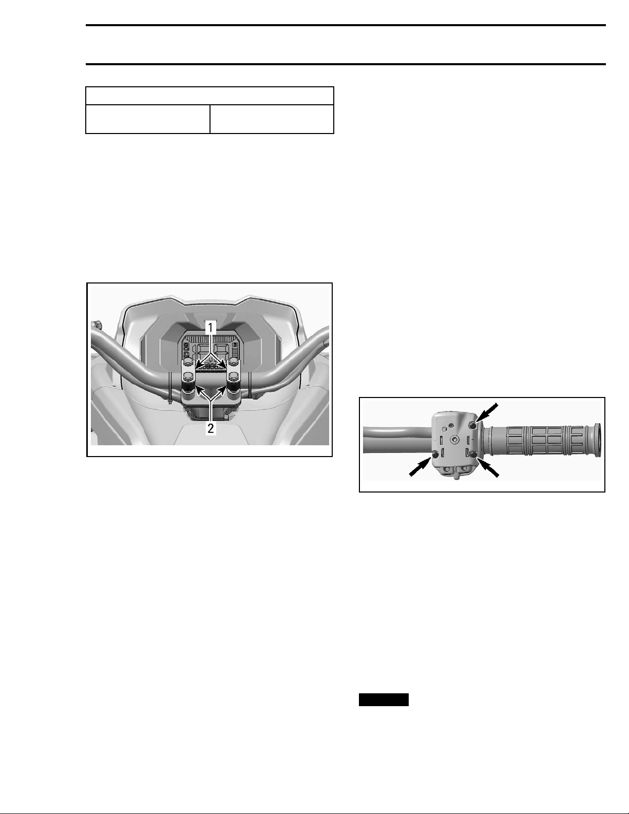
1. Remove multifunction switch screws.
LIGHTS,
vmr2012-039-004_a
TYPICAL
1. Stiffeners
2. Handlebar clamps
3. Remove the handlebar.
Handlebar Inspection
Inspect the handlebar for damage, cracks or bending. Replace if any of these problems is detected.
Installing the Handlebar
For the installation, reverse the removal procedure. However, pay attention to the following.
Make sure wheel are straight ahead. Refer to
STEERING ALIGNMENT
Position the handlebar straight ahead and tighten
its screws.
Tighten handlebar "U" clamps equally (equal distance on each side of clamps).
.
vmr2012-039-006_a
TYPICAL - MULTIFUNCTION SWITCH
2. Separate multifunction switch from handlebar.
3. Disconnect multifunction switch steering c onnectors, refer to
NECTORS
–MG1
–MG2
4. Take note of the positions of the locking ties
securing the steering harness, then cut them
and remove the multifunction switch steering
harness from the vehicle.
WIRING HARNESS AND CON-
subsection:
Installing the Multifunction Switch
For installation, reverse the removal procedure.
NOTICE
tifunction switch steering harness as noted
prior to removal.
Be sure to route and secure the mul-
vmr2016-414 5
Page 6
Subsection 01 (STEERING SYSTEM)
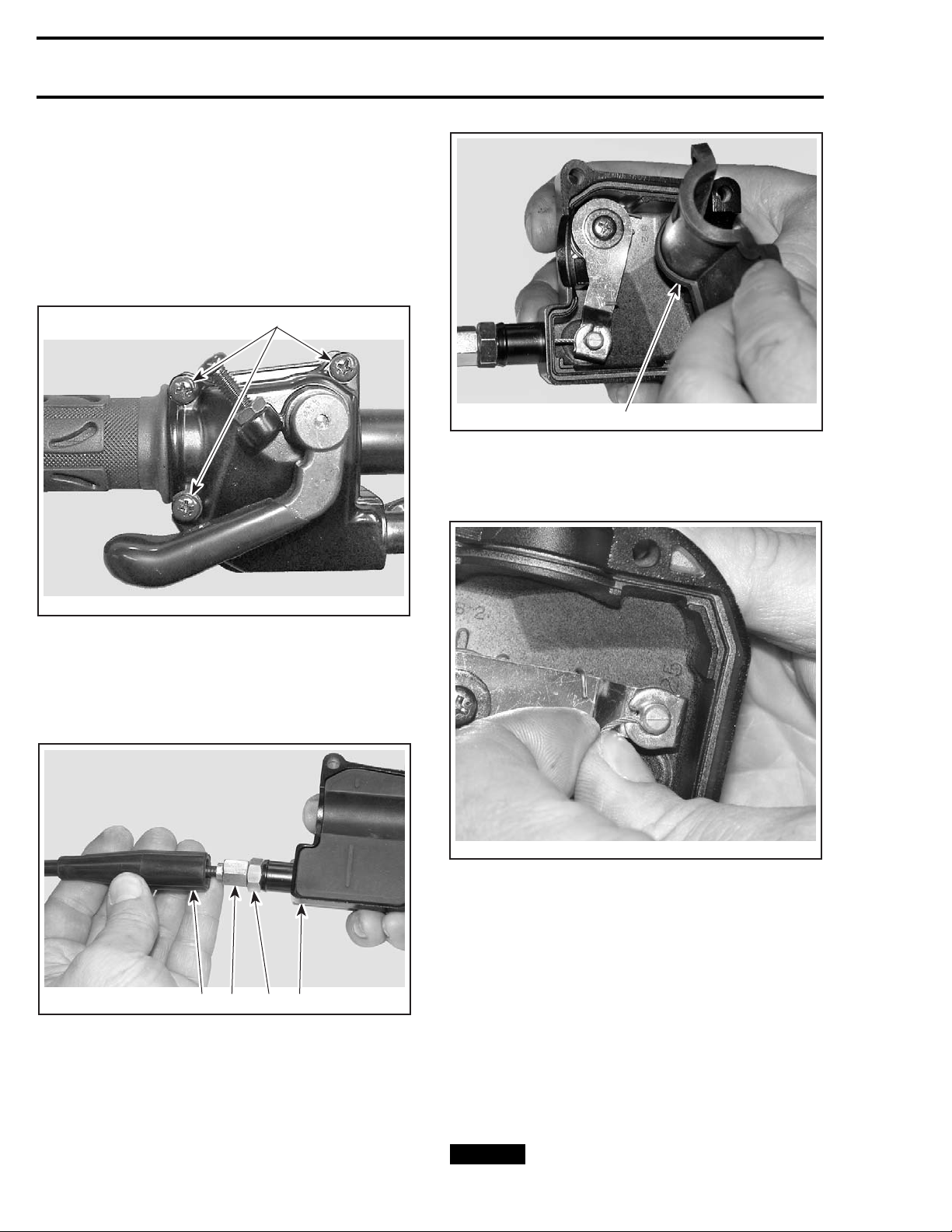
THROTTLE LEVER
Removing the Throttle Lever
1. Disconnect the BD connector (2/4WD switch),
refer to
TORS
2. Remove throttle lever housing retaining
screws.
WIRING HARNESS AND CONNEC-
subsection.
1
V07I0FA
TYPICAL - THROTTLE LEVER HOUSING
1. Remove retaining screws
3. Separate throttle lever housing from handlebar.
4. Slide rubber protector back to expose throttle
cable adjuster.
V07I0HA
1. Inner housing protector
1
7. Slide cable in clip slot and remove the end of
the cable from clip.
V07I0IA
8. Remo
ve throttle cable from housing.
Installing the Throttle Lever
nstallation, reverse the removal procedure.
For i
V07I0GA
1. Cable protector
2. Throttle cable adjuster
3. Lock nut
4. Throttle lever housing
Adjust throttle cable. Refer to
4321
ADJUSTMENT
.
BRAKE LEVER
Remo
ving the Brake Lever (From
THROTTLE CABLE
Vehic le)
5. Loosen lock nut and screw in the throttle cable
adjuster.
6. Remove inner housing protector.
6 vmr2016-414
1. Carry out steps in
BRAKE LEVER REMOVAL
(FROM HANDLEBAR)
ICE
NOT
Avoid spilling brake fluid on plastic,
rubber or painted parts.
.
Page 7
Subsection 01 (STEERING SYSTEM)
2. Disconnect brake hose, refer to
BRAKES
sub-
section.
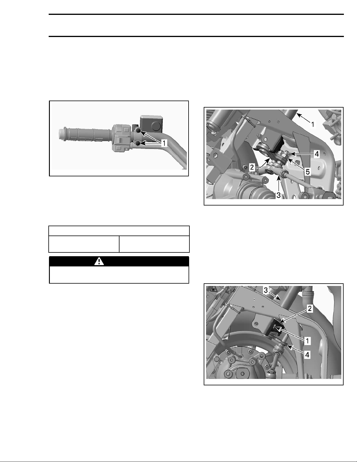
Removing the Brake Lever (At
Handlebar)
1. Remove brake lever retaining screws.
vmr2008-068-004_a
1. Retaining screws
2. Separate
brake lever from handlebar.
Installing the Brake Lever
For instal
however,
Brake lever mounting
lation, reverse the removal procedure
pay attention to the following.
TIGHTENING TORQUE
9N•m ± 1N•m
screw
(80 lbf•in ±9lbf•in)
WARNING
If brake hose was disconnected, bleed brake
system. Refer to
BRAKES
subsection.
4. Remove handlebar, refer to
HANDLEBAR
in this subsection. Also remove
REMOVING THE
locking ties and separate wiring harnesses and
hoses from the steering column.
5. Disconnect the tie-rods from the pitman arm at
the bottom of the steering column. Refer to
TIE-ROD
vmr2012-039-008_a
TYPICAL
1. Steering column
2. Pitm an arm
3. Tie-rod end
4. Cotter pin
5. Tie-rod retaining nut
, further in this section.
NOTE: When removing tie-rods from pitman arm,
take note of positions of flat washers for installation.
6. Remove lower half bushing retaining bolts and
pull retainer off of half bushings.
STEERING COLUMN BEARING
The steering column bearing(s) used on these vehicles are half bushings.
For inspection and replacement of steering column half bushings, refer to
STEERING COLUMN
in this subsection.
STEERING COLUMN
Removing the Steering Column
(Without a DPS)
1. Remove gauge support, refer to
THE MULTIFUNCTION GAUGE
GAUGE AND ACCESSORIES
2. Remove the front body module, refer to
REMOVING
in
LIGHTS,
subsection.
BODY
subsection.
3. Remove the air intake silencer. Refer to
TAKE SYSTEM
vmr2016-414 7
subsection.
AIR IN-
vmr2012-039-009_a
TYPICAL
1. Lowe
2. Lower half bushing retainer
3. Steering column
4. Pit
r retainer mounting screws (2)
man arm
7. Remove upper half bushing retaining bolts and
pull retainer off of half bushings.
Page 8
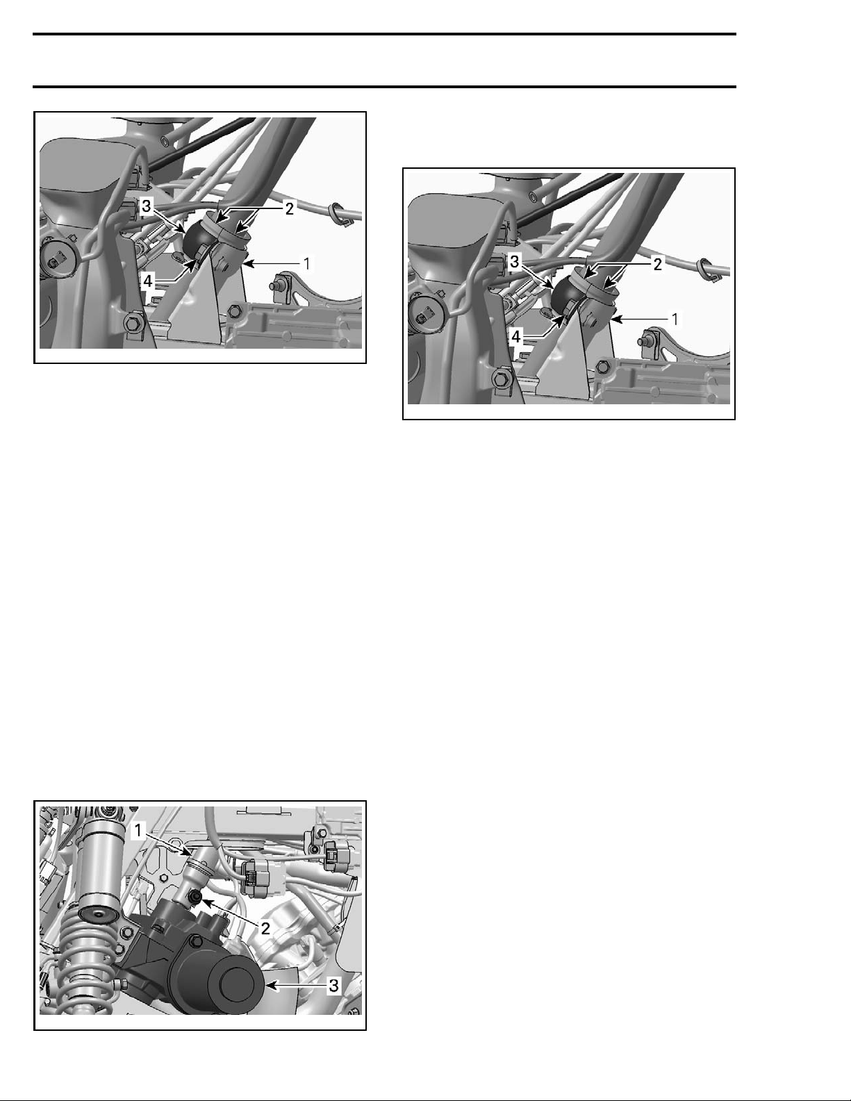
Subsection 01 (STEERING SYSTEM)
vmr2012-039-010_a
TYPICAL
1. Upper steering column support
2. Half bushings
3. Half bushing retainer
4. Retainer mounting screws (2)
8. Pull steering column from vehicle.
Removing the Steering Column (With
aDPS)
1. Remove gauge support, refer to
THE MULTIFUNCTION GAUGE
GAUGE AND ACCESSORIES
2. Remove the front body module, refer to
subsection.
3. Remove the air intake silencer. Refer to
TAKE SYSTEM
subsection.
4. Remove handlebar, refer to
HANDLEBAR
in this subsection. Also remove
locking ties and separate wiring harnesses and
hoses from the steering column.
5. Remove steering column lower pinch bolt, just
above the DPS unit.
NOTE: Some parts in following illustration not
shown for clarity of illustration.
REMOVING
in
LIGHTS,
subsection.
BODY
AIR IN-
REMOVING THE
6. Remove upper half bushing retaining bolts and
pull retainer off of half bushings.
vmr2012-039-010_a
TYPICAL
1. Upper stee
2. Half bushings
3. Half bushing retainer
4. Retainer
ring column support
mounting screws (2)
7. Pull steering column from vehicle.
Inspecting the Steering Column
1. Inspect steering column for wear, cracks or
bending. Replace if any of these problems is
detected.
2. Check st
hardnes
necess
3. Clean and check steering column half bushings.
If they show signs of wear or cracking, replace
them.
Instal
For the installation, reverse the removal procedure however, pay attention to the following.
eering column O-rings for brittleness,
s, wear or other damage. Replace if
ary.
ling the Steering Column
2012-039-011_a
vmr
1. Steering column
2. Steering column lower pinch bolt
S unit
3. DP
8 vmr2016-414
Page 9
PRODUCT
Subsection 01 (STEERING SYSTEM)
O-rings, half
bushings and DP
input shaft splines
DPS output sha
splines
XPS SYNTHETIC GREASE
S
ft
(P/N 293 550 010)
LOCTITE 767 (A
LUBRICANT) (P/N 293 800 070)
NTISEIZE
Install NEW cotter pins (as applicable per model).
Both ends of cotter pins must be folded.
Install NEW elastic nuts where used.
Torque all fa
exploded vie
Carry out a
steners as specified in the applicable
w.
STEERING ALIGNMENT
procedure as
detailed in this subsection.
With DPS
Carry out a
RQUE OFFSET RESET
TO
with
B.U.D.S..
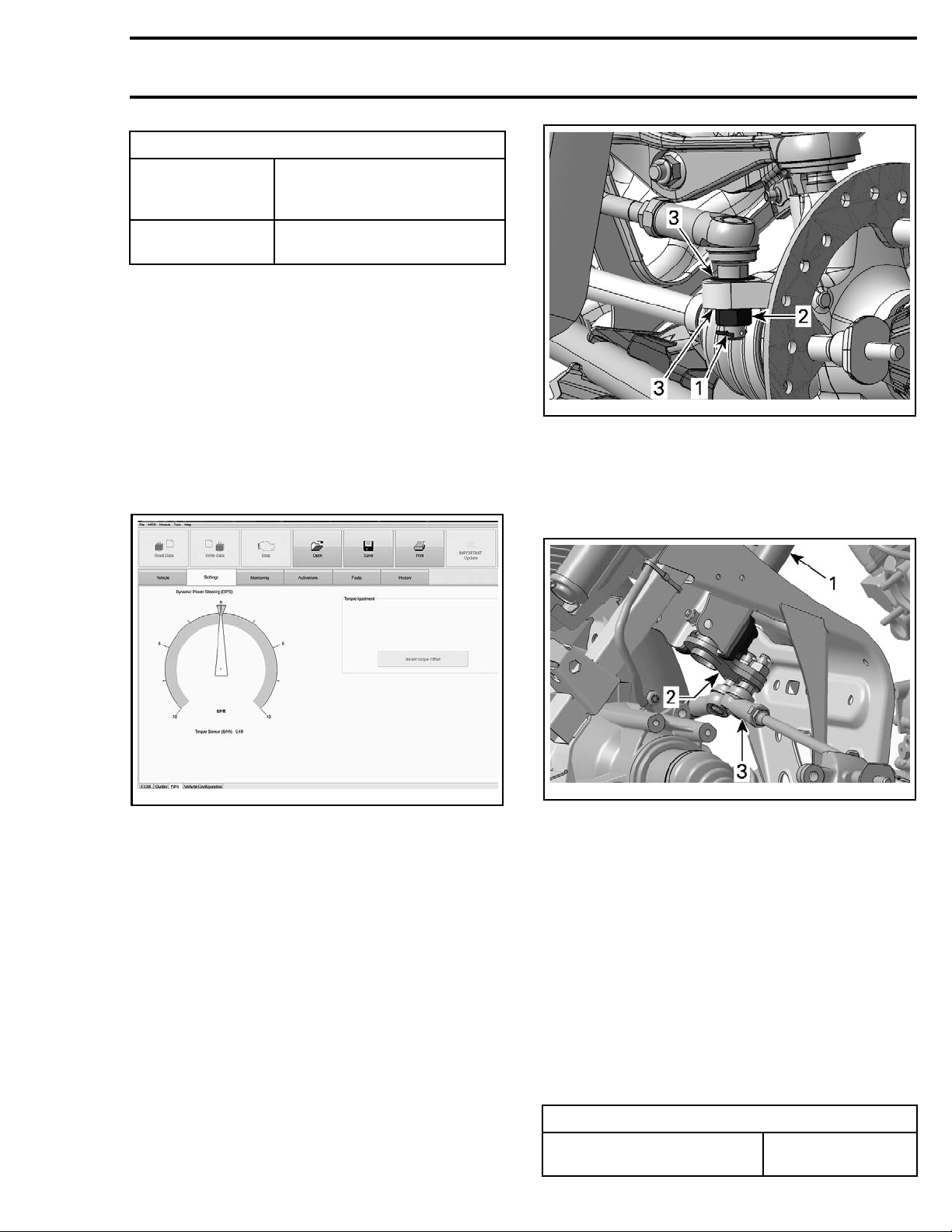
vmr2012-039-012_a
TYPICAL - TIE ROD AT STEERING KNUCKLE
1. Cotter pin
2. Elastic nut
3. Hardened washers
3. If completely removing tie-rod from vehicle, repeat previous step at pitman arm.
vmr2016-414-002
TIE-ROD
NOTE: Use
side.
Removing the Tie-Rod
1. Place ve
plicabl
the same procedure for RH and LH
hicle on jack stands and remove the ap-
e wheel.
vmr2012-039-008_b
L
TYPICA
1. Steering column
2. Pitm an arm
od end
3. Tie-r
Inspecting the Tie-Rod
ct tie-rod for straightness, cracks and other
Inspe
damag
Inspect tie-rod ends for wear or excessive play. If
excessive, replace the tie-rod end.
es. Replace as required.
2. Remove tie-rod end from steering knuckle by
lling the Tie-Rod
removing:
– Cotter p
in (discard)
– Retaining nut
– Hardened washers (note position).
Insta
For the installation, reverse the removal procedure. Pay attention to the following details.
When installing a new tie-rod or tie-rod end, adjust
tie-rod to nominal length.
TIE-ROD NOMINAL LENGTH
Dimension "A" center to center
vmr2016-414 9
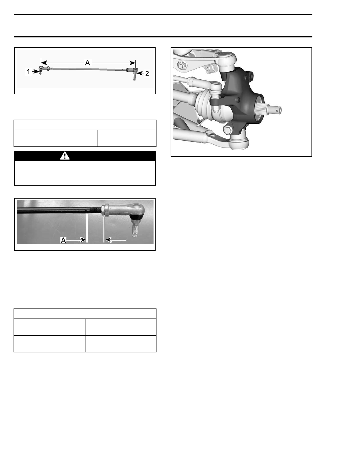
416.4 mm
(16.394 in)
Page 10
Subsection 01 (STEERING SYSTEM)
rmr2008-028-015_a
NOMINAL LENGTH
1. P i tman arm si de
2. Knuckle side
A. 416.4 mm (16.394 in)
TIE-ROD MAXIMUM UNENGAGED LENGTH
Dimension "A" - Shoulder
to tie rod end face
32 mm (1.26 in)
WARNING
Maximum tie-rod unengaged length must
not exceed specification. Both tie-rod ends
must be engaged equally.
tmr2011-034-107_a
MAXIMUM TIE-ROD UNENGAGED LENGTH
A. 32 mm (1.26 in)
Install NEW cotter pins. Both ends of cotter pins
must be folded.
Check the steering alignment, refer to
ALIGNMENT
in this subsection.
STEERING
Apply specified torques.
TIGHTENING TORQUE
Tie - r o d l
Tie rod e
nd retaining nut
KNUCKL
ock nut
E
34 N•m ± 2 N•m
(25lbf•ft± 1lbf•ft)
72 N•m ± 7 N•m
(53lbf•ft± 5lbf•ft)
Removing the Knuckle
1. Safely
2. Remove front wheel.
3. Detach tie-rod end from knuckle, refer to
ROD END
4. Remov
tion.
5. Remove wheel hub, refer to
subsection.
lift and support the front of vehicle.
in this subsection.
e brake caliper, refer to
BRAKES
subsec-
FRONT DRIVE
TIE-
vmr2015-141-003
6. Detach upp
fer to
er suspension arm from knuckle, re-
FRON
T SUSPENSION
.
7. Detach lower suspension arm from knuckle, refer to
FRONT SUSPENSION
.
8. Remove knuckle from vehicle.
Inspecting the Knuckle
Check knuckle for cracks or other damages. Replace if necessary.
Check if w
See
heel bearing turns freely and smoothly.
WHEEL
BEARING
in this subsection.
Installing the Knuckle
The insta
dure.
WHEEL BE
llation is the reverse of removal proce-
ARINGS
Inspecting the Wheel Bearing
(Mainte
Refer to
DURES
Inspect
nance)
PERIODIC MAINTENANCE PROCE-
subsection.
ing the Wheel Bearing (During
Component Removal)
Whenever the drive axle or knuckle is removed,
check wheel bearing as follows:
– Check if wheel bearing turns freely and
smoothly.
– Check s
Replace if necessary.
Removi
1. Remove knuckle from v ehicle, refer to
ING THE KNUCKLE
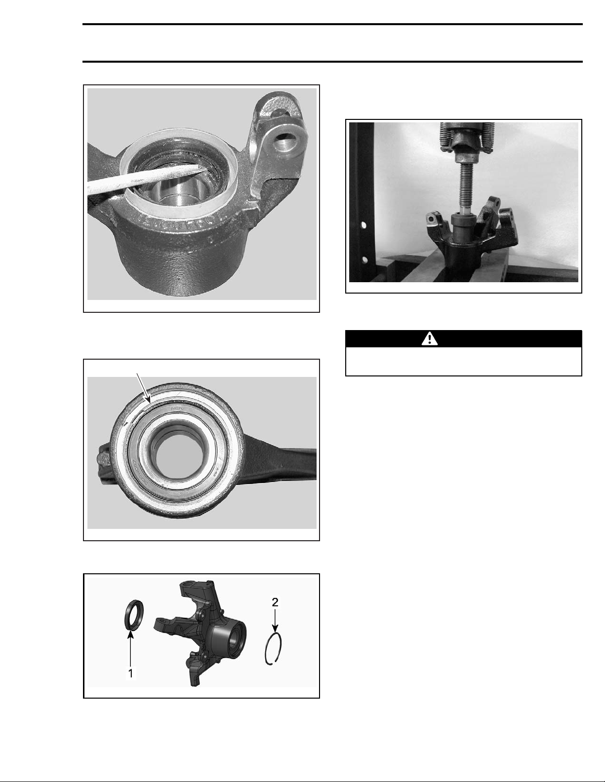
2. Remove and discard knuckle seal.
eal condition.
ng the Wheel Bearing
REMOV-
in this subsection.
10 vmr2016-414
Page 11
Subsection 01 (STEERING SYSTEM)
5. Remove bearing from knuckle using an appropriate bearing remover.
34-109
tmr2011-0
V07I0RA
TYPICAL
3. Remove the circlip.
1
V07I0SA
TYPICAL
1. Circlip
NOTE: It may be necessary to heat the knuckle to
remove bearing.
WARNING
Clean all grease from outside and inside of
knuckle before heating it.
Installing the Wheel Bearing
The installation is the reverse of the removal procedure. However, pay attention to the following.
To ease wheel bearing installation:
– Place bearing in a freezer for 10 minutes.
– Place knuckle in oven to 100°C (212°F) for
30 minutes maximum.
When knuckle is cooled down, install NEW circlip
and NEW seal.
PITMAN ARM (WITH A DPS)
Refer to
subsection.
DYNAMIC POWER STEERING (DPS)
2011-034-015_a
tmr
TYPICAL
1. Seal
clip
2. Cir
4. Install knuckle on a press.
vmr2016-414 11
 Loading...