

Page 1
Subsection 05 (STARTING SYSTEM)
STARTING SYSTEM
SERVICE TOOLS
Description Part Number Page
ECM ADAPTER TOOL................................................................... 529 036 166 ........................................... 4
FLUKE 115 MULTIMETER ............................................................ 529 035 868 ........................................... 5
GENERAL
STARTING SYSTEM OPERATION
When the START button is pressed, 12 Vdc is applied through the start switch (MG1) to the starter
solenoid coil. If the engine cranking conditions are
met, the ECM completes the starter solenoid control circuit by providing a ground. The starter solenoid then closes its contacts and battery power
is applied to the starter for cranking the engine.
Engine Cranking Conditions
The following conditions must be met to allow engine cranking.
– Ignition switch turned ON
– EnginestopswitchtoRUN
– Transmission in Park, Neutral or a brake
pedal/lever is applied
– Start button is pressed and held.
TROUBLESHOOTING
Check for fault codes. Refer to:
AND FAULT CODES
subsection.
DIAGNOSTIC
ENGINE WILL NOT TURN
4. Starter (refer to
subsection)
5. Wiring and connections.
MAGNETO AND STARTER
ENGINE TURNS
Starting system is OK.
1. Verify ignition system. Refer to
subsection.
TEM
2. Verify EFI systems. Refer to
FUEL INJECTION (EFI)
3. Verify mechanical condition of engine. Refer to
subsection.
ENGINE, CVT AND GEARBOX
IGNITION SYS-
ELECTRONIC
section.
PROCEDURES
Ensure battery is fully charged.
Refer to applicable
NECTORS
tions on vehicle.
Refer to applicable
tional information.
Ensure vehicle is in PARK when performing
starting system tests.
for harness layout and connector loca-
WIRING HARNESS AND CON-
WIRING DIAGRAM
for addi-
WARNING
If the starter cranks over the engine with the
brakes applied, check the following:
1. Shifter rod adjustment, (refer to appropriate
SHIFTER
2. Gearbox position indicator switches or the
gearbox position sensor (GBPS), (refer to appropriate
UNIT
3. Switches or sensor wires a nd connectors, (refer to appropriate
If the “Engine cranking conditions” are met and
the starter will not crank the engine, check the following:
1. Battery and connections (refer to
SYSTEM
2. Starter solenoid
3. Start button switch
vmr2016-136 1
subsection
GEARBOX AND 4X4 COUPLING
subsection
WIRING DIAGRAM
CHARGING
)
).
Page 2
Subsection 05 (STARTING SYSTEM)
STARTING SYSTEM TESTS
Starter Solenoid
-
vmr2015-135-001_a
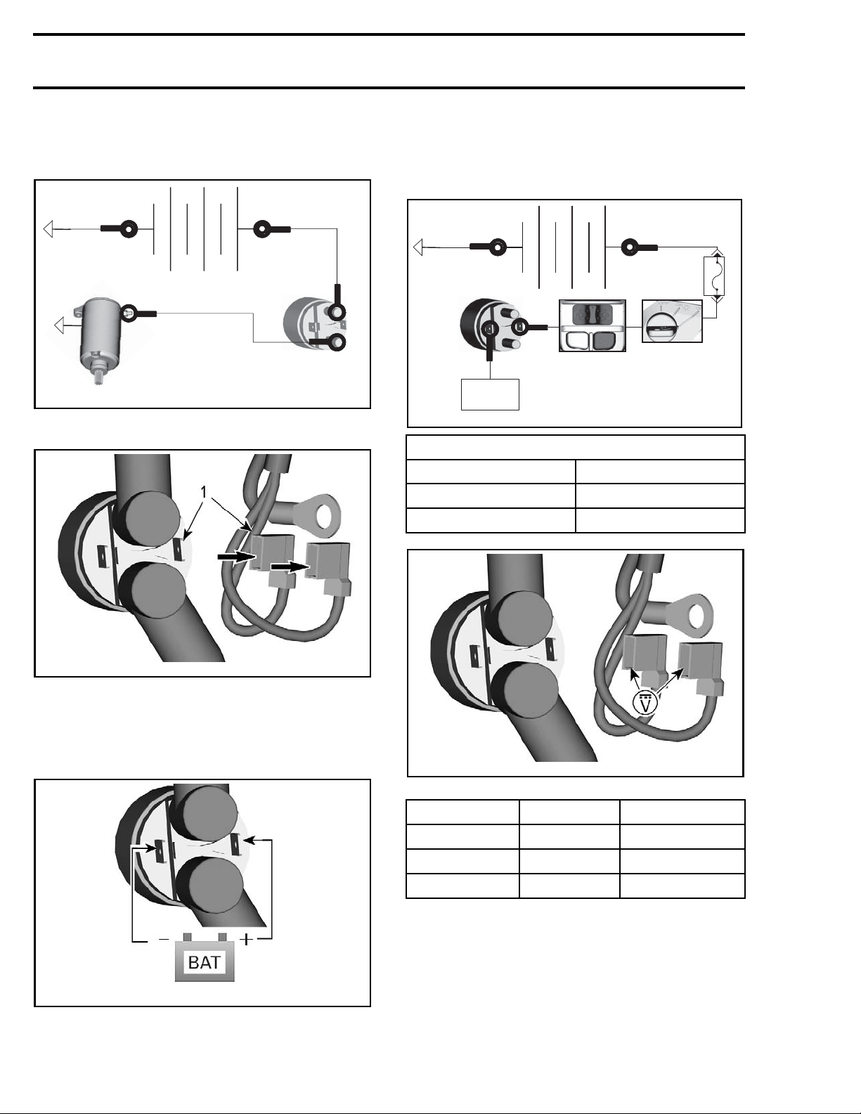
1. Disconnect SS1 and SS2
+
4. If starter does not turn, verify
NOID CONTINUITY
.
STARTER SOLE-
Starter Solenoid Control Circuit
-
ECM
vmr2015-135-003_a
TEST CONDITION
Engine stop switch RUN
Ignition switch
Start button
+
ON
Pressed
F8
5 A
vmr2015-048-012_a
1. SS1
2. Activate the starter solenoid.
2.1 Apply 12Vdc to SS1
2.2 Ground SS2
vmr2015-048-003_c
SS1 IS ON THE RIGHT
3. If starter turns, verify
CONTROL CIRCUIT
STARTER SOLENOID
.
vmr2015-048-003_a
SS1 IS ON THE RIGHT
PROBE PROBE SPECIF
SS1 SS2
SS1
BAT +
BAT - Battery voltage
SS2
Battery voltage
Battery voltage
ICATION
If voltage is as per specification replace starter solenoid.
If volt
ify
CIRCUI
GROUND
age is not as per specification, ver-
RTER SOLENOID CONTROL POWER
STA
T
or
STARTER SOLENOID CONTROL
CIRCUIT
as applicable.
Starter Solenoid Control Power Circuit
NOTE: T
his procedure also tests the start button.
2 vmr2016-136
Page 3
Subsection 05 (STARTING SYSTEM)
6
1
5A
F
2
1
B
ECM
STOP
RUN
FREE
START
-101_a
vmr2016-136
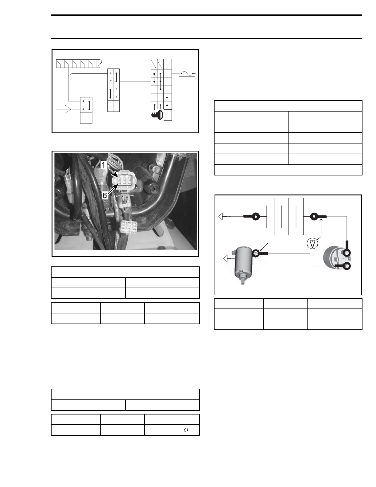
1. Disconnect MG2 connector.
ON/
OFF
ON/
WO LIGHT
W LIGHT
F8
B
F
A
D
C
E
If start switch tests as specified, repair wire to
starter solenoid SS1 terminal.
Starter Power Circuit Voltage Drop
NOTE: Engine must be in starting condition for
this test. Do not perform on a «No Start» vehicle.
TEST CONDITION
Fuse F5 Removed‡
Engine stop s
Ignition switch
Start button
Engine
witch
RUN
ON
Pressed
Cranking
‡ Will prevent engine from starting
-
tage drop.
+
1. Measure vol
vmr2008-139-003_a
TYPICAL - MG2 STEERING HARNESS CONNECTOR PIN-OUT
TEST CONDITION
Engine s
PROBE PROBE SPECIFICATION
MG2-1
top switch
Ignition switch
RUN
ON
BAT - Batter
yvoltage.
-135-004_a
vmr2015
PROBE PROBE SPECIFICATION
BAT1
Starter B+
terminal
Below 0.4 Vdc
2. If voltage is not as per specification:
1. Check fuse(s)
2. Test engine stop switch. Refer to
SYSTEM
3. Test ignition switch Refer to
TEM
subsection
IGNITION SYS-
subsection.
IGNITION
If voltage drop is above specification, repair or replace sources of high resistance in circuit.
3. Test start button.
TEST CONDITION
Start
button
Pressed
PROBE PROBE SPECIFICATION
MG2-1 MG2-6 Close to 0
If start button does not test as specified, replace
the multifunction switch assembly.
vmr2016-136 3
Page 4
Subsection 05 (STARTING SYSTEM)
BAT1
BAT2
1
3
Starter Solenoid Control Ground
Circuit
SS2-
L3
B4
HIC1-J
ECM
G2
K3
A4
vmr2015-048-005_a
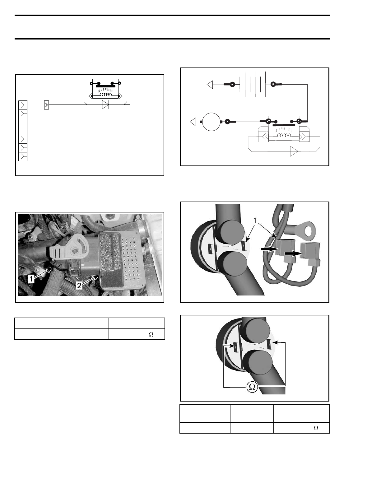
1. Disconnect SS2.
2. Install the ECM connector onto the
ADAPTER TOOL (P/N 529 036 166)
SS1-
ECM
Starter Solenoid Continuity
M
BP
vmr2016-136-100_a
1. Disconnect the BLACK (-) negative battery cable.
2. Disconnect SS1 and SS2
BP
vmr2008-139-016_a
1. ECM connector
2. ECM ada
pter tool
PROBE PROBE SPECIFICATION
SS2 ECM-L3 Close to 0
If resistance is not as specified, repair or replace
wiring/connections.
If solenoid power control c ircuit and ground control circuit both test good, test ECM ground
circuits. Refer to
subsection.
(EFI)
ELECTRONIC FUEL INJECTION
NOTE: Supply a ground with a jumper wire if you
suspect that the ECM is not supplying a ground to
the solenoid.
vmr2015-048-012_a
1. SS1
vmr2015-048-003_d
PROB
E
PROB
E
SPECIFICATION
@ 20°C (68°F)
SS1 SS2 Close to 6
If resistance is not as per specification, replace the
solenoid.
3. Disconnect BP3.
4 vmr2016-136
Page 5
Subsection 05 (STARTING SYSTEM)
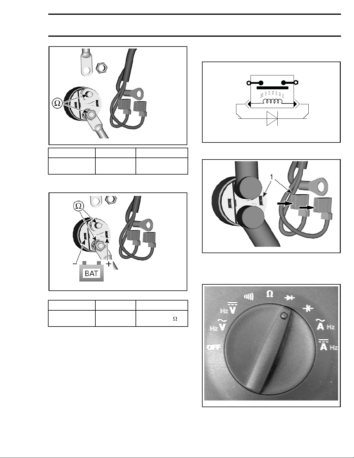
Solenoid Diode Test
vmr2015-048-007_a
PROBE PROBE SPECIFICAT
BP3
Ter m in a l t o
starter mo
tor
4. Jump starter solenoid.
O.L.
ION
SS2-
vmr2015-048-013_a
SS1-
1. Disconnect SS1 and SS2 from starter solenoid.
-048-012_a
vmr2015
1. SS1
2. Use the FLUKE 115 MULTIMETER (P/N 529 035
868)
and set it to the diode symbol as shown.
vmr2015-048-009_a
SS1 IS ON THE RIGHT
PROBE PROBE SPECI
BP3
Ter m in a l t o
er motor
start
FICATION
Closeto0
If resistance is not as per specification, replace the
solenoid.
arter power and ground circuits are good, re-
If st
o
fer t
star
MAGNETO AND STARTER
ter diagnosis and replacement.
subsection for
vmr2006-020-005
3. Probe wires w hile paying attention to the diode
polarity.
vmr2016-136 5
Page 6
Subsection 05 (STARTING SYSTEM)
8-011_a
vmr2015-04
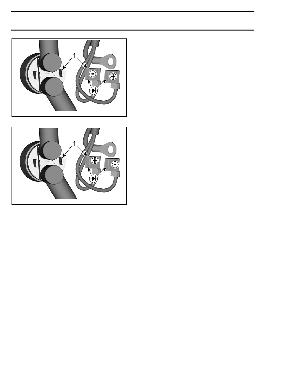
FORWARD POLARITY, MUST BE AROUND 0.5 V
vmr2015-048-010_a
REVERSE POLARITY, MUST BE OPEN CIRCUIT
1. SS1
If test failed, replace diode. Refer to
HARNESS AND CONNECTORS
for diode loca-
WIRING
tion.
NOTE: The diode is integrated in the harness near
the starter solenoid.
6 vmr2016-136
 Loading...