

Page 1
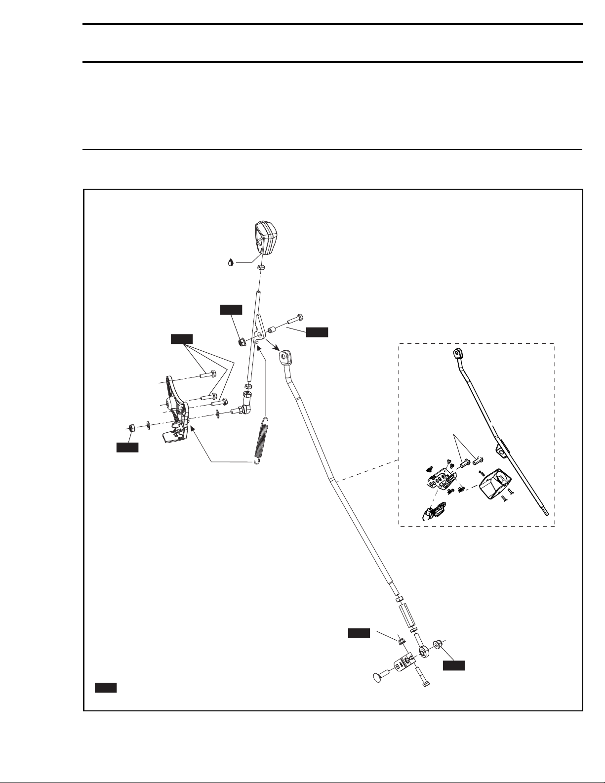
Subsection 16 (SHIFTER (GEARBOX WITH GBPS))
SHIFTER (GEARBOX WITH GBPS)
SERVICE PRODUCTS
Description Part Number Page
LOCTITE 243 (BLUE)..................................................................... 293 800 060 ........................................... 2
Loctite 243
NEW
5 ± 1 N•m
(44 ± 9 lbf•in)
NEW
NEW
NEW
10 ± 2 N•m
(89 ± 18 lbf•in)
= Component must be replaced when removed.
NEW
vmr2016-407-001_a
13 ± 2 N•m
(115± 18 lbf•in)
Renegade CE models
9 ± 1 N•m
(80 ± 9 lbf•in)
NEW
NEW
vmr2016-407 1
Page 2
Subsection 16 (SHIFTER (GEARBOX WITH GBPS))
PROCEDURES
HANDLE
Handle Remova
vmr2015-024-002_a
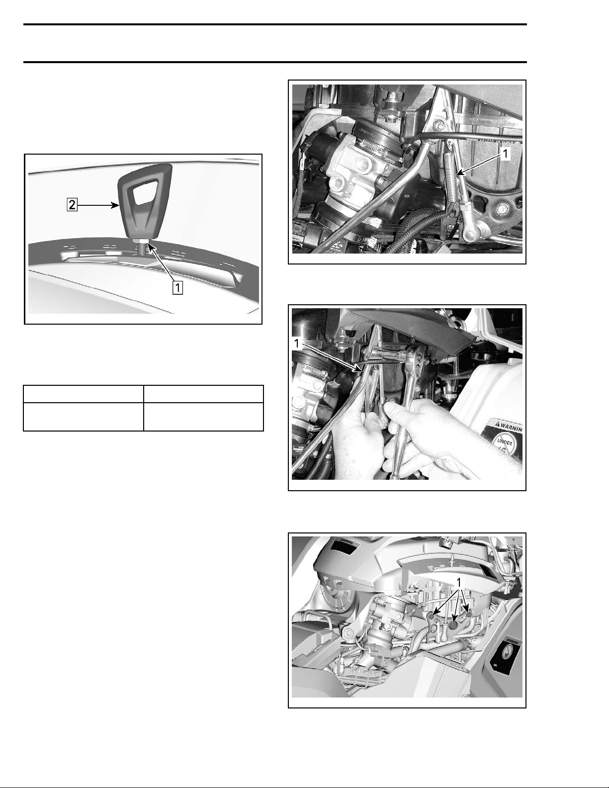
Step 1: Loosen lock nut
Step 2 : Unscrew shift lever handle
l
Handle Installation
Reverse the removal procedure.
SERVICE PRODUCT WHERE USED
LOCTITE 243 (BLUE)
(P/N 293 800 060)
Shift leve
vmr2012-021-002_a
1. Unhook
6. Detach shift rod from shift lever.
r threads
SHIFT LEV
ER
Shift Lever Access
ODY
1. Refer to
lowing co
B
subsection and remove the fol-
mponents:
–Seat
– Console
–RHsidep
anel.
Shift Lever Removal
1. Remove b
LEVER A
2. Place shift lever in NEUTRAL position.
3. Secure vehicle using wheel chocks.
4. Unscre
5. Unhook spring.
ody parts as required. Refer to
CCESS
in this subsection.
w shift lever handle.
SHIFT
2-021-003_a
vmr201
1. Detach
7. Detach shift lever support.
vmr2012-021-004_a
1. Remove bolts
8. Remove shift lever.
2 vmr2016-407
Page 3
Subsection 16 (SHIFTER (GEARBOX WITH GBPS))
Shift Lever Inspection
Check shift lever for bending or cracks.
Check spring and bushing condition.
Check ball joint condition.
Replace all damaged parts.
Shift Lever Installation
The installation is the reverse of the removal pro-
cedure. However, pay attention to the following.
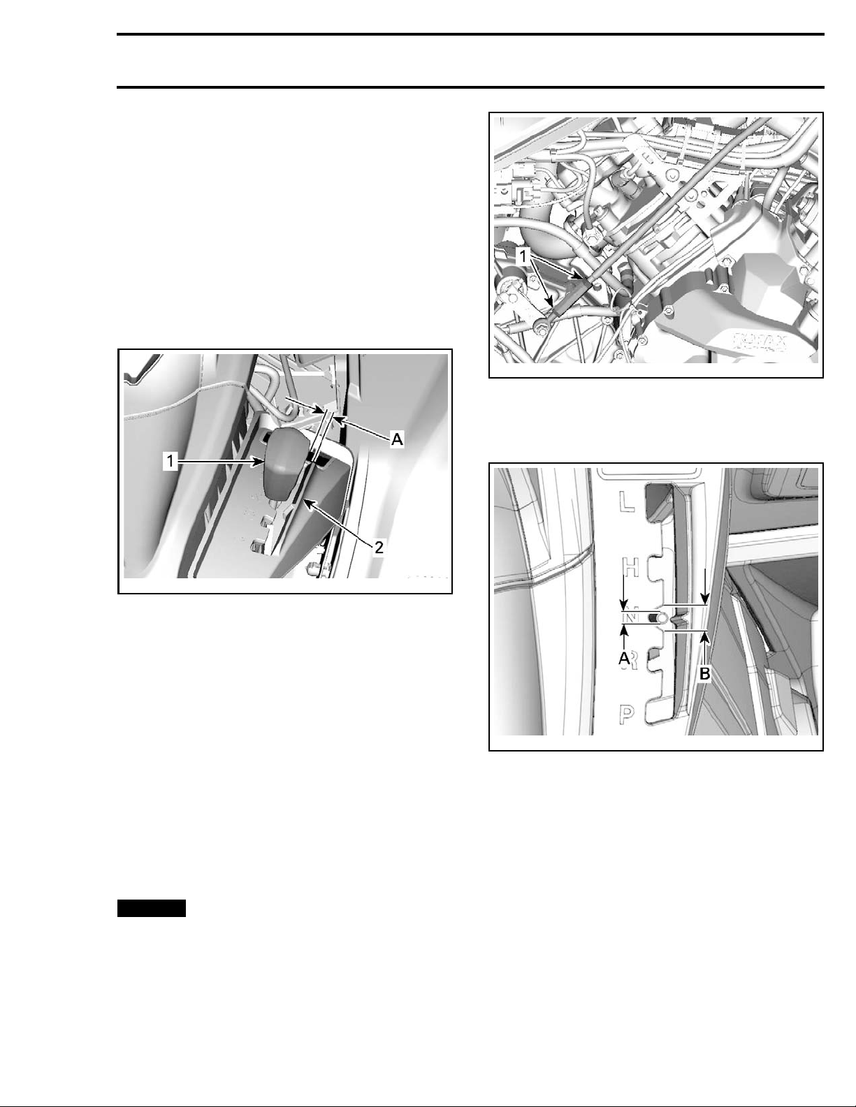
Adjust shift lever handle as per the following illus-
tration.
vmr2012-021-007_a
TYPICAL — SOME PARTS REMOVED FOR CLARITY
1. Adjustment nuts
5. Turn rod adjuster to center shift lever in neutral
notch.
vmr2012-021-005_a
SHIFT LEVER
1. Handle
2. Ridge
A. Handle par
HANDLE ALIGNMENT
allel with ridge
Check if shift lever works properly in all positions.
Ensure throttle cable does not interfere with shift
lever in all positions.
NOTE: Shif
with the ne
gaged in n
If adjustment is required, refer to
JUSTMENT
t lever must be perfectly centered
utral mark when transmission is en-
eutral.
SHIFT ROD AD-
in this subsection.
SHIFT ROD
Shift Rod
1. Place shift lever in NEUTRAL position.
NOTICE
sure gear
2. Secure vehicle using wheel chocks.
3. Remove b
LEVER AC
4. Loosen shift rod adjustment nuts.
NOTE: Be aware that a nut has LH threads.
Adjustment
Move vehi
box is set in neutral position.
ody parts as required. Refer to
CESS
cle back and forth to en-
in this subsection.
SHIFT
vmr2012-021-006_a
SHIFT LEVER CENTERED WITHIN NEUTRAL NOTCH
A. Shift l
B. Neutral notch
ever
6. Move shift lever in R position then in H.
7. Place shift lever in NEUTRAL position.
8. Check
tral
if shift lever is properly centered in neu-
notch. Readjust as required.
9. Hold adjuster steady and tighten lock nuts.
10. Test the shifter to confirm that the system
works properly in all positions.
NOTE
with
shif
: Make sure the ball joint is properly aligned
the shift plate. It may be necessary to realign
t rod ball joints to allow easy movement.
vmr2016-407 3
Page 4
Subsection 16 (SHIFTER (GEARBOX WITH GBPS))
WARNING
After adjustment, make sure that PARK position works properly.
SHIFT PLATE
Shift Plate Removal
NOTE: Do not remove shift plate needlessly.
1. Place shift lever in NEUTRAL position.
2. Refer to
engine cover.
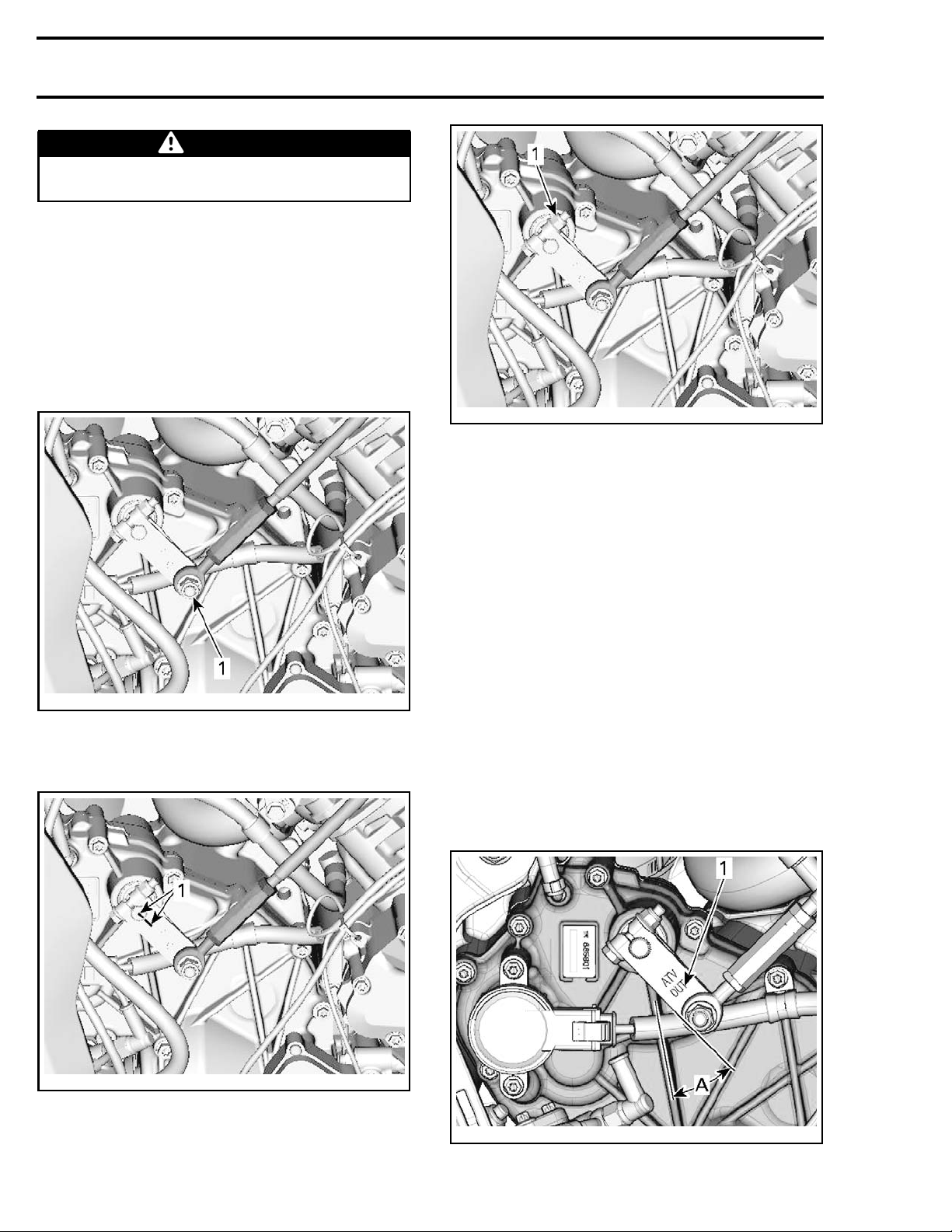
3. Remove shift rod from shift plate.
BODY
subsection and remove the RH
vmr2012-021-008_c
1. Shift plate nut
6. Remove shift plate.
Shift Plate Inspection
Check shift plate for:
–Cracks
– Bending
– Spline condition.
-021-008_a
vmr2012
1. Remove nut
4. Trace an index mark on shift plate and shift
shaft.
Shift Plate Installation
The installation is the reverse of the removal procedure. However, pay attention to the following.
Place gearbox in NEUTRAL position before shift
plate installation.
Position shift plate with the marking "ATV OUT"
visible outward.
Align shift plate using marks previously traced.
If there is no mark, adjust shift plate as per follow-
ing illustrations.
vmr2012-021-008_b
1. Trace a mark on both parts
5. Remove shift plate nut and bolt.
4
12-021-010_a
vmr20
1. "ATV OUT" marking this side
A. 34°
vmr2016-407
Page 5
Subsection 16 (SHIFTER (GEARBOX WITH GBPS))
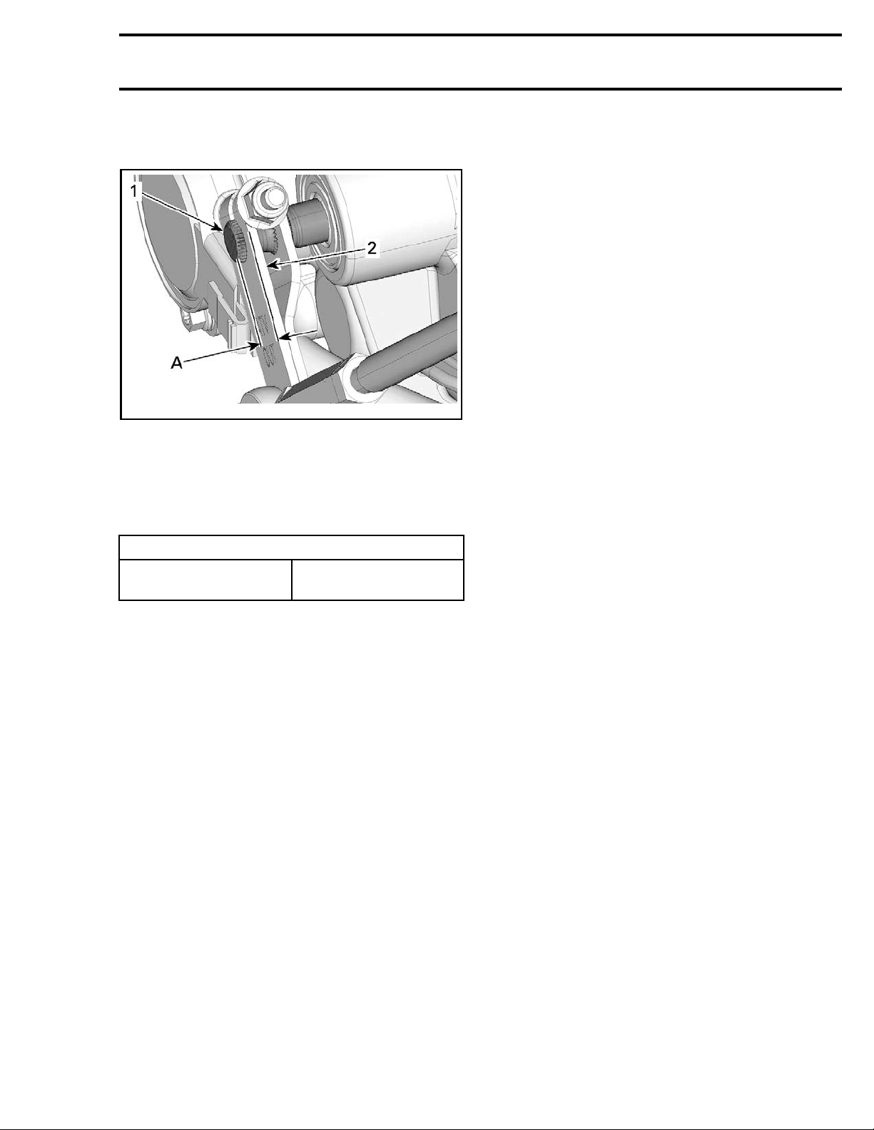
Ensure that shift shaft protrudes shift plate as per
illustration.
vmr2012-021-011_a
1. Shift shaft end
2. Shift plat
A. 2.5mm± 1mm (.1in ± .040in)
e
Adjust shift rod, refer to
MENT
in this subsection.
SHIFT ROD ADJUST-
Tighten shift plate nut to specification.
TIGHTENING TORQUE
Shift pla
te nut
9N•m ± 1N•m
(80 lbf•in ±9lbf•in)
vmr2016-407 5
 Loading...