

Page 1

Section 07 DRIVE SYSTEM
Subsection 03 (REAR DRIVE)
REAR DRIVE
SERVICE TOOLS
Description Part Number Page
BACKLASH MEASUREMENT TOOL............................................. 529 035 665 ......................................... 620
CV BOOT CLAMP PLIER .............................................................. 529 036 120 ......................................... 616
CV JOINT EXTRACTOR................................................................. 529 036 005 ......................................... 617
SPANNER SOCKET ....................................................................... 529 035 649 ......................................... 623
SERVICE PRODUCTS
Description Part Number Page
LOCTITE 277 ................................................................................. 293 800 073 ......................................... 625
LOCTITE 648 (GREEN) .................................................................. 413 711 400 ......................................... 619
XPS SYNTHETIC GREASE................................................. ............ 293 550 010 .................................615, 618
vmr2015-052 611
Page 2
Section 07 DRIVE SYSTEM
Subsection 03 (REAR DRIVE)
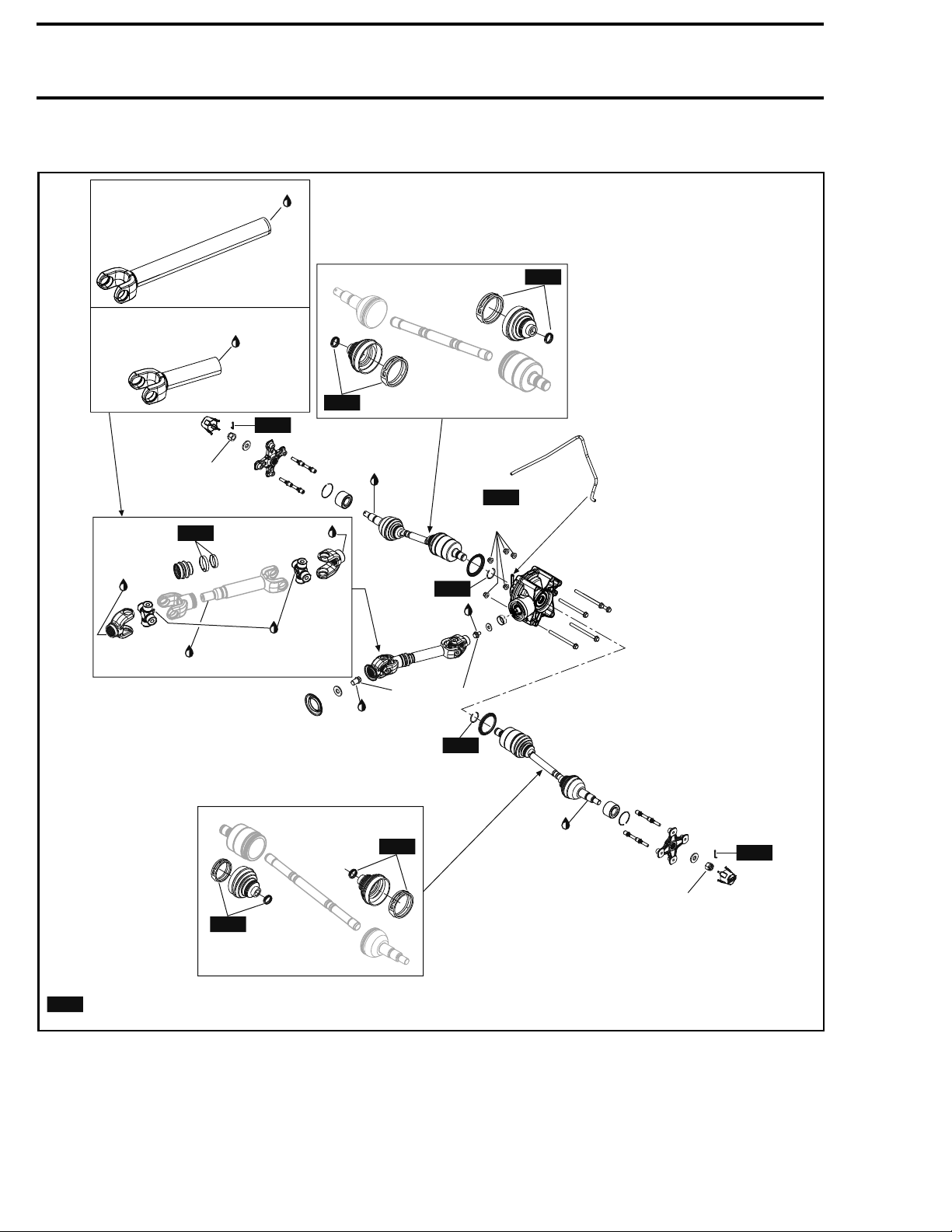
MODELS WITH 500 ENGINE
XPS Synthetic
grease
MAX models
NEW
Short models
205 ± 15 N•m
(151 ± 11 lbf•ft)
NEW
XPS
Synthetic
grease
XPS Synthetic
grease
XPS Synthetic
grease
NEW
NEW
XPS Synthetic
grease
Hi-temp bearing grease
NLGI-2 or equivalent
XPS Synthetic
grease
NEW
90 ± 5 N•m
(66 ± 4 lbf•ft)
NEW
Loctite
648
75 ± 5 N•m
(55 ± 4 lbf•ft)
Loctite
648
NEW
NEW
NEW
= Component must be replaced when removed.
NEW
vmr2015-052-100_a
612 vmr2015-052
XPS Synthetic
grease
NEW
205 ± 15 N•m
(151 ± 11 lbf•ft)
Page 3
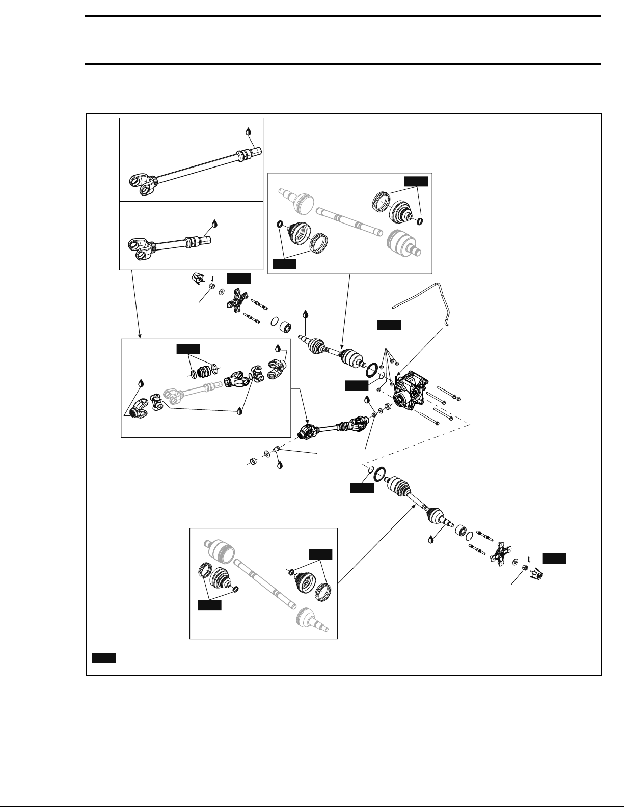
MODELS WITH 450 ENGINE
XPS Synthetic
grease
MAX models
Section 07 DRIVE SYSTEM
Subsection 03 (REAR DRIVE)
NEW
Short models
205 ± 15 N•m
(151 ± 11 lbf•ft)
NEW
XPS
Synthetic
grease
XPS Synthetic
grease
NEW
NEW
XPS Synthetic
grease
Hi-temp bearing grease
NLGI-2 or equivalent
Loctite
648
XPS Synthetic
grease
NEW
90 ± 5 N•m
(66 ± 4 lbf•ft)
NEW
Loctite
648
75 ± 5 N•m
(55 ± 4 lbf•ft)
NEW
NEW
NEW
= Component must be replaced when removed.
NEW
vmr2015-052-101_a
vmr2015-052 613
XPS Synthetic
grease
NEW
205 ± 15 N•m
(151 ± 11 lbf•ft)
Page 4
Section 07 DRIVE SYSTEM
Subsection 03 (REAR DRIVE)
NEW
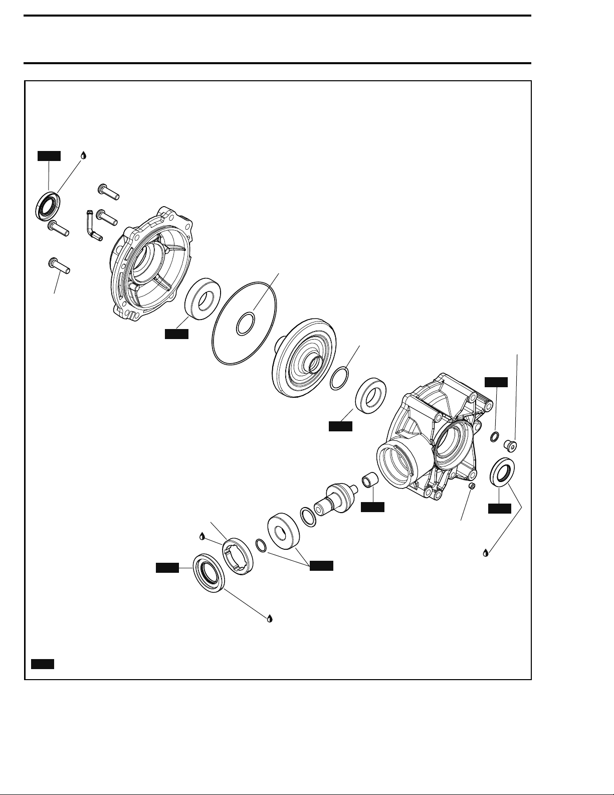
32 ± 3 N•m
(24 ± 2 lbf•ft)
XPS synthetic
grease
NEW
For preload
adjustment
NEW
For backlash
adjustment
22.5 ± 2.5 N•m
(17 ± 2 lbf•ft)
NEW
180 ± 15 N•m
(133 ± 11 lbf•ft)
LH threads
Loctite 277
NEW
XPS synthetic grease
= Component must be replaced when removed.
NEW
vmr2015-052-102_a
614 vmr2015-052
NEW
NEW
NEW
5 ± 1 N•m
(44 ± 9 lbf•in)
XPS synthetic
grease
Page 5
Section 07 DRIVE SYSTEM
Subsection 03 (REAR DRIVE)
PROCEDURES
WHEEL HUB
Wheel Hub Remo
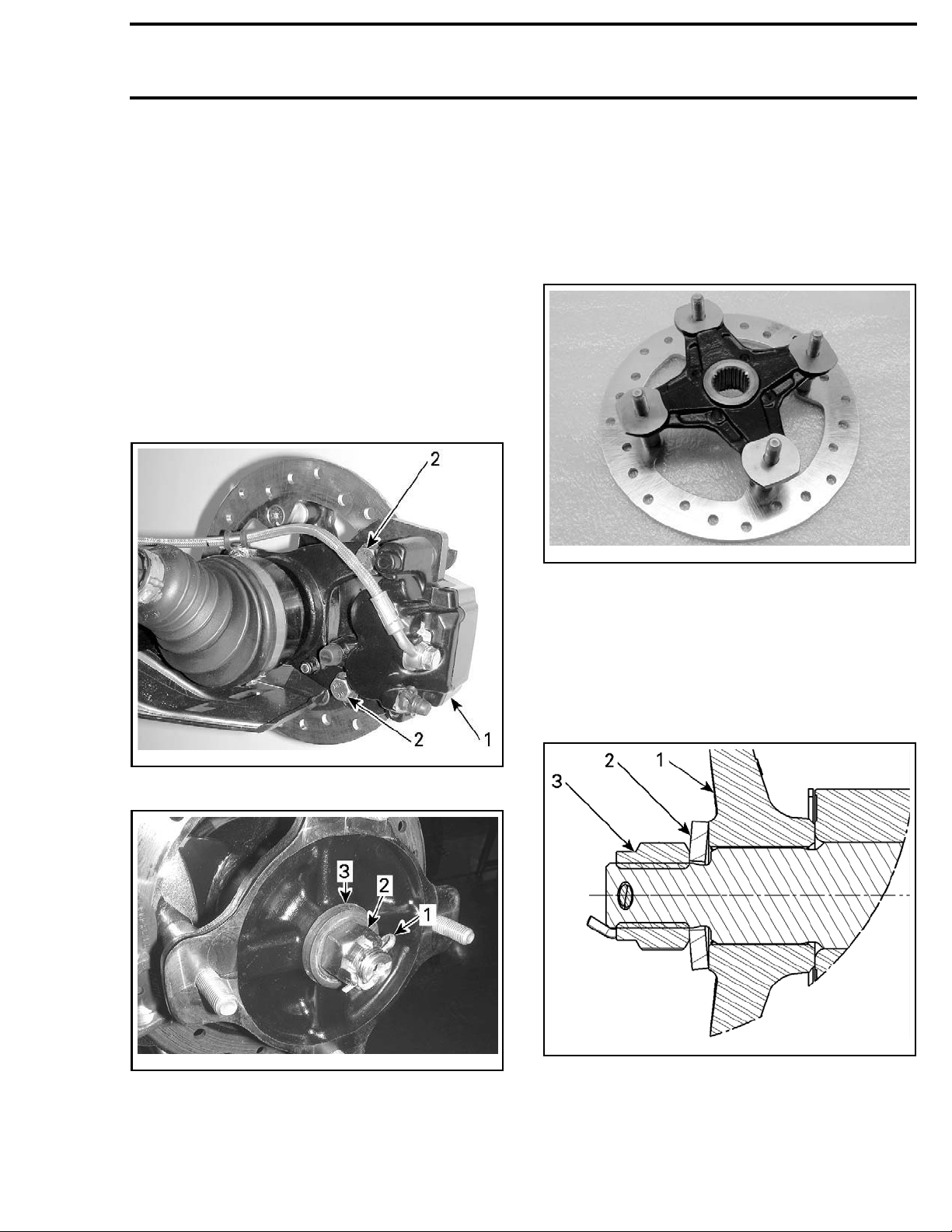
Lift and support vehicle.
Remove the wheel.
Remove the foll
– Caliper mounting bolts (if applicable), refer to
BRAKES
– Hub cap
– Cotter pin
– Wheel hub nut
– Belleville washer.
subsection
val
owing parts:
Wheel Hub Inspection
Remove disk from RH wheel hub as necessary.
Check wheel hub for cracks or other damages.
Check inner splines for wear or other damages.
If any damage is detected on wheel hub, replace
it with a new one.
vmr2012-037-004
Wheel Hub Installation
The installation is the reverse of the removal procedure. However, pay attention to the following:
Apply
drive shaft splines.
Install Belleville washer with its convex side outward.
XPS SYNTHETIC GREASE (P/N 293 550 010) on
vmr2012-037-003_a
1. Caliper
2. Remove bolts
tmr2011-032-003_a
TYPICAL
1. Co tter pin
2. Wheel hub nut
3. Belleville washer
vmr2012-037-005_a
1. Wheel h
2. Washer — Convex side here
3. Nut
ub
Remove wheel hub.
vmr2015-052 615
Page 6
Section 07 DRIVE SYSTEM
Subsection 03 (REAR DRIVE)
TIGHTENING TOR
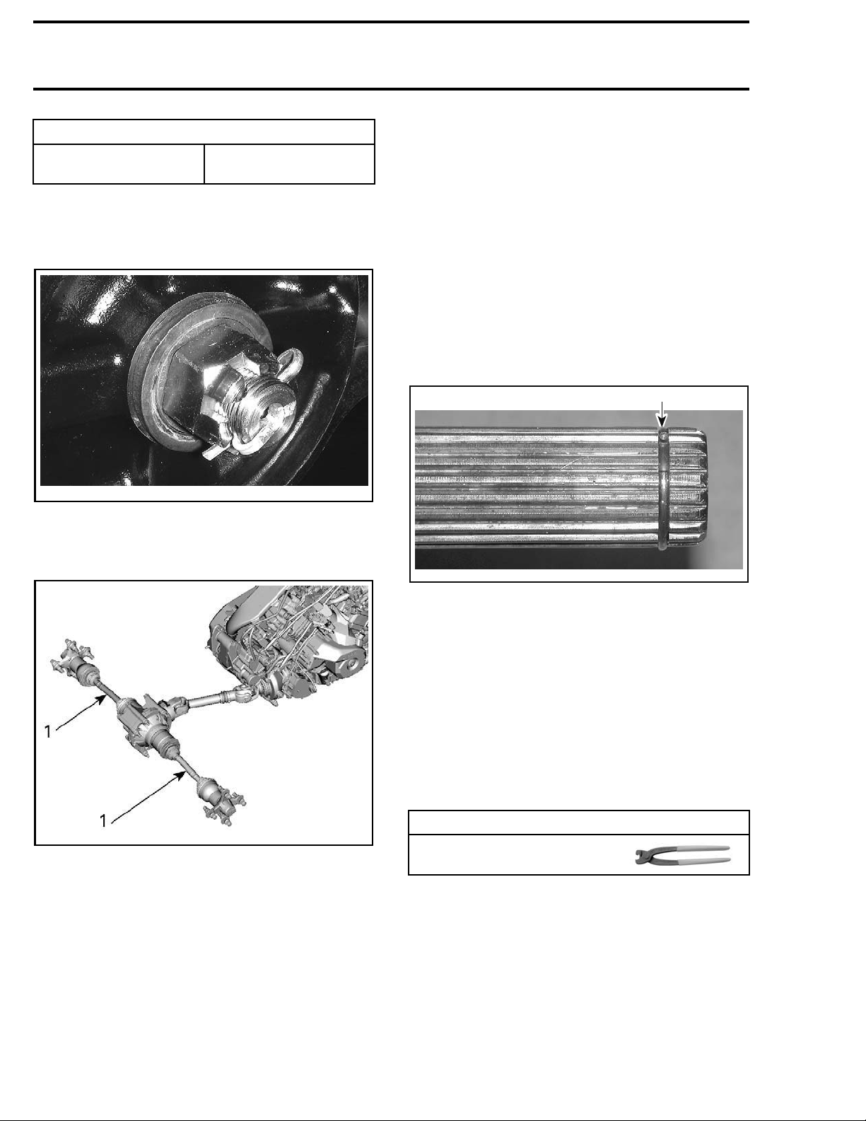
Wheel hub nut
QUE
205N•m ± 15N•m
(151 lbf•ft ± 1
1lbf•ft)
NOTE: If required, tighten castellated nut further
to align grooves with drive shaft hole.
Install a NEW
tmr2011-032-005
DRIVE SHA
cotter pin.
FT
Drive Shaft Inspection
Inspect the condition of boots. If there is any damage or evidence of leaking lubricant, replace them.
Refer to
DRIVE SHAFT BOOT
.
Check shaft splines. Replace drive shaft if necessary.
Check dust shield on drive shaft end. Replace if
necessary.
Drive Shaft Installation
The installation is the reverse of the removal procedure. However, pay attention to the following:
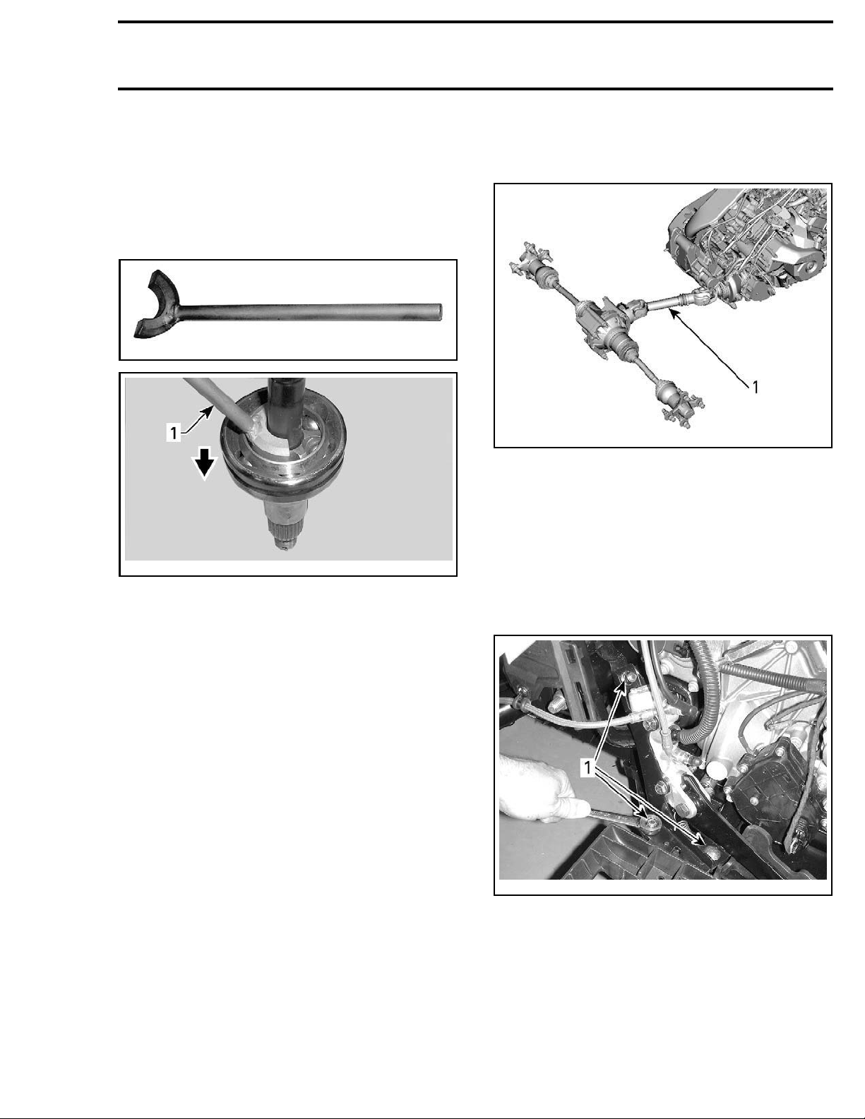
Install a NEW stop ring.
1
Drive Shaft Removal
vmr2012-037-014_a
TYPICAL
1. Drive shafts
Lift and support vehicle.
Remove the wheel hub. See procedure in this
subsection.
Remove trailing arm. Refer to
.
SION
Strongly pull drive shaft out of final drive.
REAR SUSPEN-
V07H0AA
TYPICAL
1. NEW stop ri
ng
After drive shaft insertion in rear final drive, validate if properly locked.
DRIVE SHAFT BOOT
Drive Shaft Boot Removal
Remove the drive shaft from vehicle. See procedure in this subsection.
Remove dr
ing tool:
CV BOOT CLAMP PLIER
Dislodge the large boot end.
Separate the joint from the shaft. Two procedures
can be done.
Without the Special Tool
Clamp joint housing in a vise.
Align shaft with joint.
Pull hard on shaft to remove from joint.
Remove boot from drive shaft.
ive shaft boot clamps using the follow-
TOOL
(P/N 529 036 120)
616 vmr2015-052
Page 7
Section 07 DRIVE SYSTEM
Subsection 03 (REAR DRIVE)
Remove and discard the circlip. A new one is included in the boot kit.
With the Special Tool
Place drive shaft in vice with the joint downward.
Install the
CV JOINT EXTRACTOR (P/N 529 036 005)
on bearing.
529036005
vmr2007-053-010_b
TYPICAL — CV JOINT SHOWN
1. Joint extractor tool
With an hammer, hit on the tool to separate joint
from shaft.
When joint and shaft are separated, remove boot
from drive shaft.
Remove and discard the circlip. A new one is included in the boot kit.
Remove drive shaft boot.
PROPELLER SHAFT
Propeller Shaft Removal
vmr2012-037-014_b
TYPICAL
1. Propeller shaft
1. Lift and support rear end of vehicle.
2. Remove wheels. Refer to
TIRES
subsection.
3. Drain oil from rear final drive. Refer to
ODIC MAINTENANCE PROCEDURES
4. Detach brake master cylinder from frame. Refer to
BRAKES
subsection.
WHEELS AND
PERI-
.
Drive Shaft Boot Installation
The installation is the reverse of the removal procedure. However, pay attention to the following:
Pack bearing area with grease (included with the
new boot kit).
NOTE: Do not use any other grease.
vmr2015-052 617
vmr2012-037-006_a
1. Remove retaining screws
Page 8
Section 07 DRIVE SYSTEM
Subsection 03 (REAR DRIVE)
vmr2012-037-007_a
1. Master cylinder moved apart
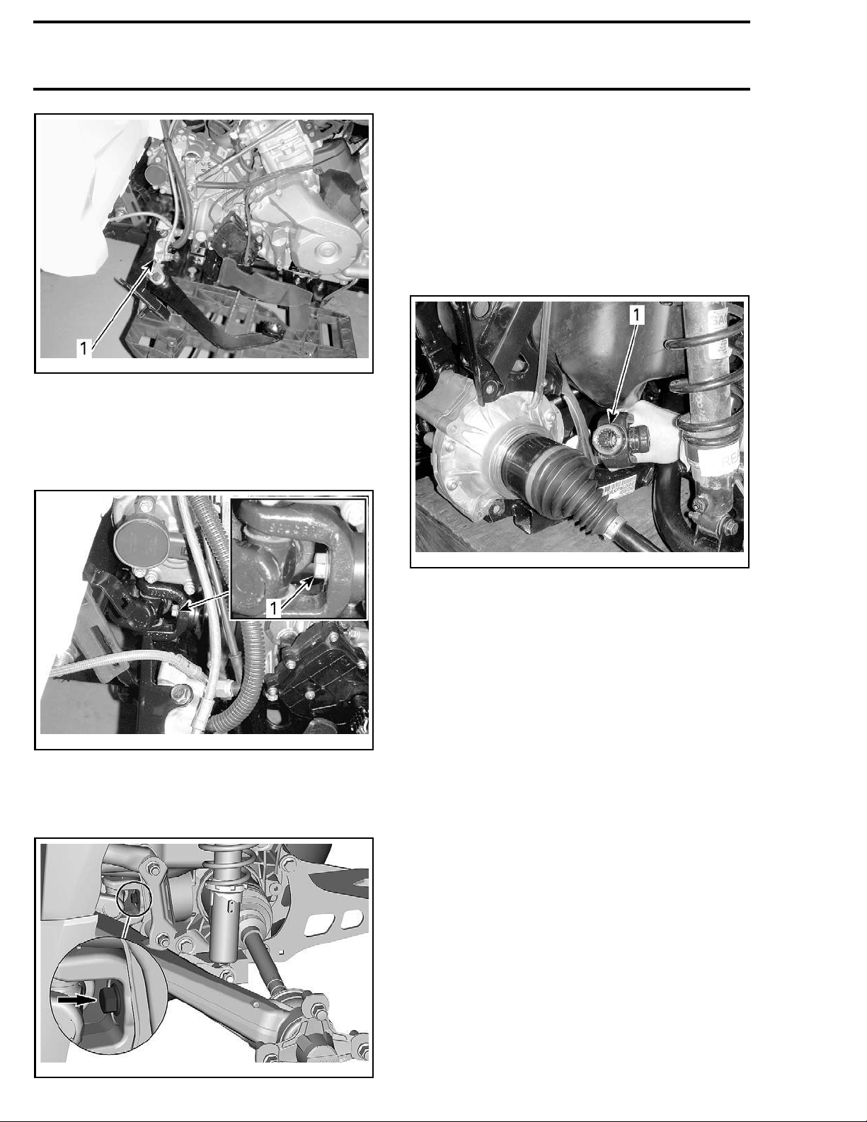
5. From RH side of vehicle, remove propeller shaft
screw from gearbox output shaft.
NOTE: Heat screw to break the threadlocker
bond prior to removal.
7. Remove rear final drive retaining bolts. Refer to
REAR FINAL DRIVE
in this subsection.
8. Remove bolts from rear retaining plate. Refer
REAR FINAL DRIVE
to
in this subsection.
9. Move the rear final drive rearward t o allow dislodging the propeller shaft.
10. Dislodge the propeller shaft from the gearbox.
11. Remove the propeller shaft.
vmr2012-037-008_a
AL — RH SIDE OF VEHICLE
TYPIC
1. Remove screw
6. From LH side of vehicle, remove propeller shaft
screw from rear final drive yoke.
vmr2012-037-012_a
1. Pull out propeller shaft
Propell
er Shaft Inspection
Inspect if propeller s haft is not bent or twisted.
Check propeller shaft splines for wear or damage.
Check if
or britt
propeller shaft bellow is cracked, pierced
le.
Propeller Shaft Installation
The inst
cedure.
Apply
splines.
allation is the reverse of the removal pro-
However, pay attention to the following:
XPS SYNTHETIC GREASE (P/N 293 550 010) to
vmr2015-052-001_a
LH SIDE OF VEHICLE
618 vmr2015-052
Page 9
Section 07 DRIVE SYSTEM
Subsection 03 (REAR DRIVE)
PARTS TO R Q U E
75 N•m ± 5 N•m
Propeller shaft screw
(rear final dr
Propeller shaft screw
(gearbox si
ive side)
de)
LOCTITE 648 (GREEN)
LOCTITE 648 (GREEN)
Refill rear final drive. Refer to
NANCE PROCEDURES
subsection.
(55lbf•ft± 4l
(P/N 413 711 4
75 N•m ± 5 N•m
(55 lbf•ft ± 4
(P/N 413 711
PERIODIC MAINTE-
bf•ft)
+
00)
lbf•ft)
+
400)
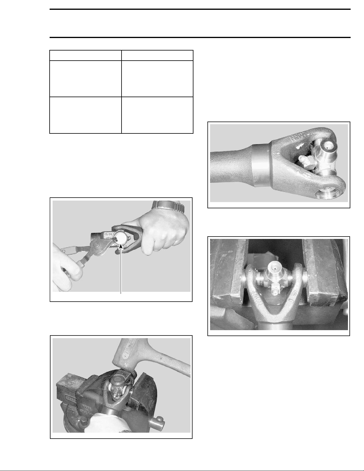
PROPELLER SHAFT U-JOINTS
Propeller Shaft U-Joint Removal
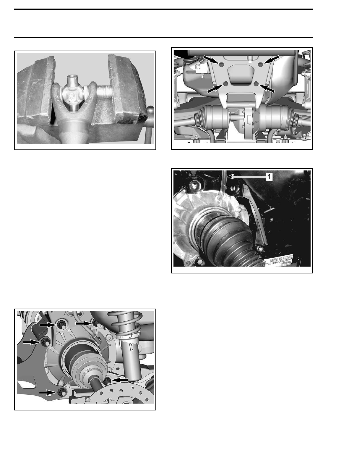
Remove internal snap ring from bearing caps.
Support U-joint in vice and drive inner yoke down
to remove remaining bearing caps.
Remove U-joint cross.
Propeller Shaft U-Joint Installation
Install a NEW U-joint in inner yoke.
NOTE: Position propeller shaft U-joint as shown
for proper grease fitting location.
V01H10A
Install bearing caps. Use a vise to push bearing
caps.
V01H0YA
1. Snap ring
1
Support inner yoke in vice and drive other yoke
downwithasofthammer.
V01H11A
Using a suitable pusher, fully seat bearing cap on
one side.
V01H0ZA
vmr2015-052 619
Page 10
Section 07 DRIVE SYSTEM
Subsection 03 (REAR DRIVE)
V01H12A
Install snap ring.
Complete installation for the other bearing caps.
Grease U-joint. Refer to
NANCE PROCEDURES
PERIODIC MAINTE-
subsection.
REAR FINAL DRIVE
Rear Final Drive Removal
Drain oil. Refer to
PROCEDURES
Lift and support vehicle.
Support rear bottom end of frame.
Remove drive shafts. See procedure in this sub-
section.
Remove rear propeller shaft screw from the rear
final drive yoke. Refer to
this subsection.
Remove rear final drive screws (5x).
PERIODIC MAINTENANCE
subsection.
PROPELLER SHAFT
in
vmr2015-052-003_a
Unplug the vent hose from final drive.
vmr2012-037-015_a
1. Pull out
Remove
the final drive.
Rear Final Drive Inspection
(Assem
Manually turn rear final drive gear; it should turn
smoothly. Repair if necessary.
Check if oil seals are brittle, hard or damaged. Replace if necessary.
bled)
Backla
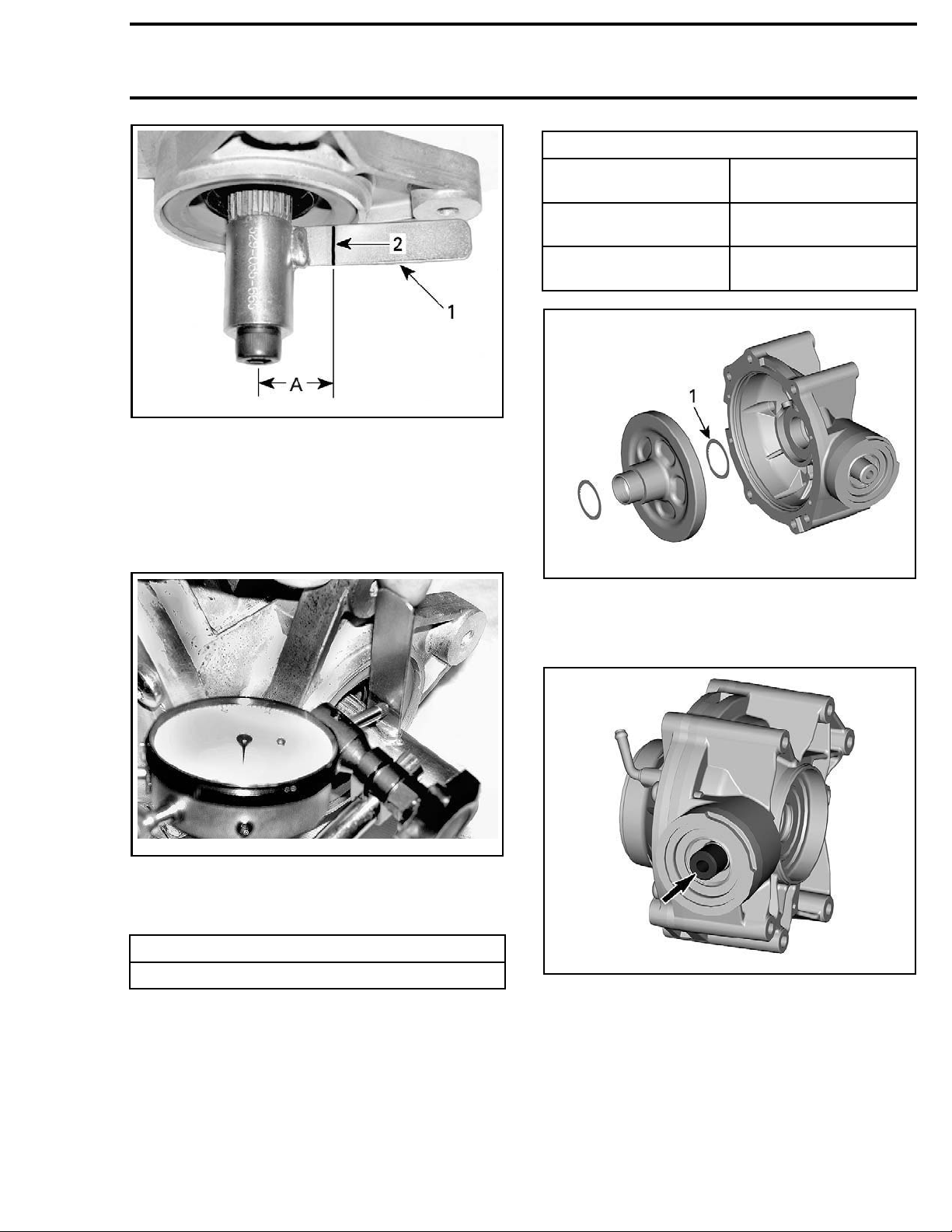
Using a dial indicator and the
SUREMENT TOOL (P/N 529 035 665)
sh Inspection
BACKLASH MEA-
, measure the
backlash.
Place the backlash measurement tool at the end
of pinion gear.
vmr2015-052-002_a
From ce
and sc
nter of tool bolt, measure 25.4 mm (1 in)
ribe a mark on the tab.
Remove bolts from rear retaining plate.
620 vmr2015-052
Page 11
Section 07 DRIVE SYSTEM
Subsection 03 (REAR DRIVE)
vmr2006-023-015_a
1. Tab of backlash measurement tool
2. Mark on tab
A. 25.4 mm (1 in)
Position the dial indicator tip against the tab at a
90° angle and right on the previously scribed mark.
Gently, move the tool tab back and forth. Note the
backlash result.
BACKLASH ADJUS
BACKLASH
MEASUREMENT
Below 0.1 mm (.004 in)
Above 0.35 mm (.014 in)
vmr2015-052-004_a
1. Backlash shim
TMENT GUIDELINE
WHAT TO DO
Add shim(s) and recheck
backlash
Remove shim(s) and
recheck bac klas h
6-023-016
vmr200
Rotate pinion gear 1/2 turn and recheck backlash.
Note the result.
Rotate pinion gear 1 turn and recheck backlash.
BACKLASH SPECIFICATION
0.1 mm (.004 in) to 0.35 mm (.014 in)
If backlash is out of specification, split final drive
housing and adjust shim thickness as per following guideline.
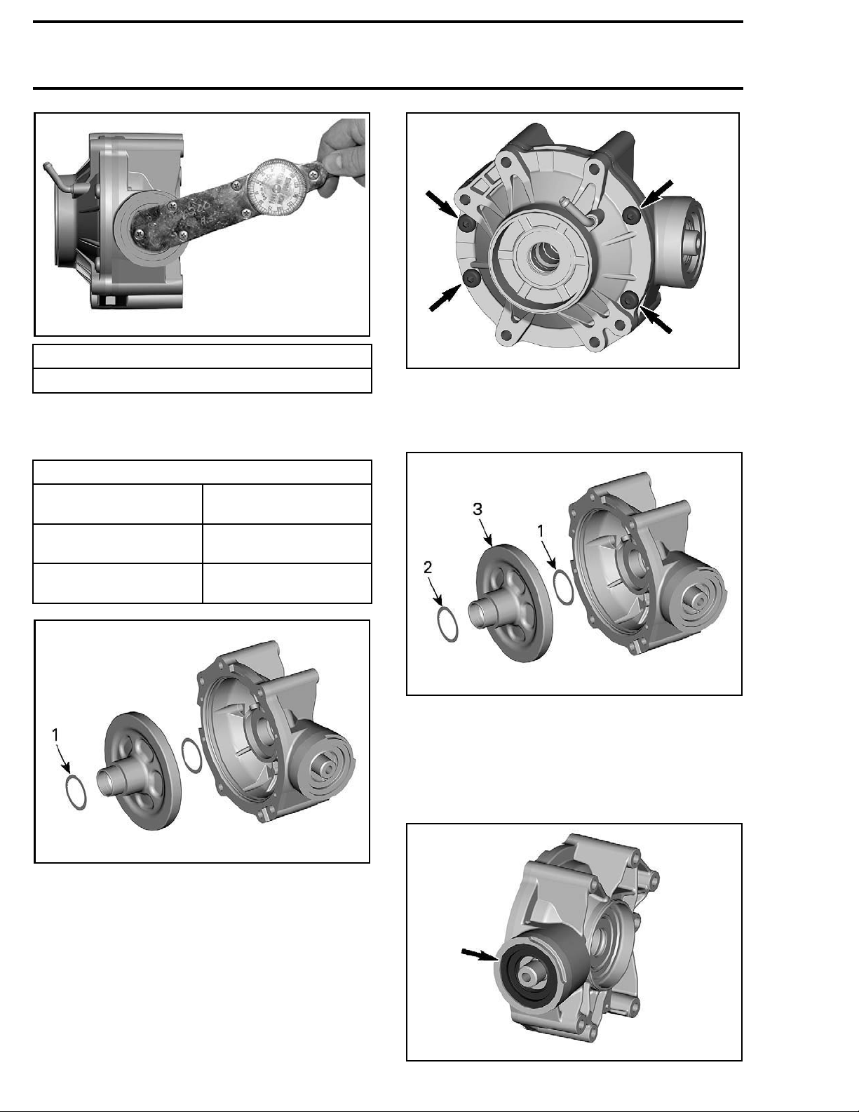
Preload Inspection
Screw the propeller shaft screw in pinion gear.
15-052-005_a
vmr20
Using a needle torque wrench, measure the
preload.
vmr2015-052 621
Page 12
Section 07 DRIVE SYSTEM
Subsection 03 (REAR DRIVE)
vmr2015-052-006_a
PRELOAD SPECIFICATION
0.06 N•m (.5 lbf•in)to0.50N•m(4lbf•in)
If preload is out of specification, split final drive
housing and adjust shim thickness as per following guideline.
PRELOAD GUIDELINE
PRELOAD
MEASUREM
ENT
Below 0.06 N•m
in)
(.5 lbf•
Above 0.50 N•m
n)
(4 lbf•i
WHAT TO DO
Add shim(s) and recheck
preload
Remove shim(s) and
recheck
preload
vmr2015-052-007_a
Split final drive housings.
NOTE: Be careful to keep track of shims on ring
gear.
vmr2015-052-004_c
1. Backla
2. Preload shim
3. Ring gear
Extrac
sh shim
t ring gear out of half housing.
Pinion Gear
Remove and discard oil seal.
vmr2015-052-004_b
oad shim
1. Prel
Rear Final Drive Disassembly
Gear
Ring
Remove the final drive housing screws.
vmr2015-052-008_a
622 vmr2015-052
Page 13
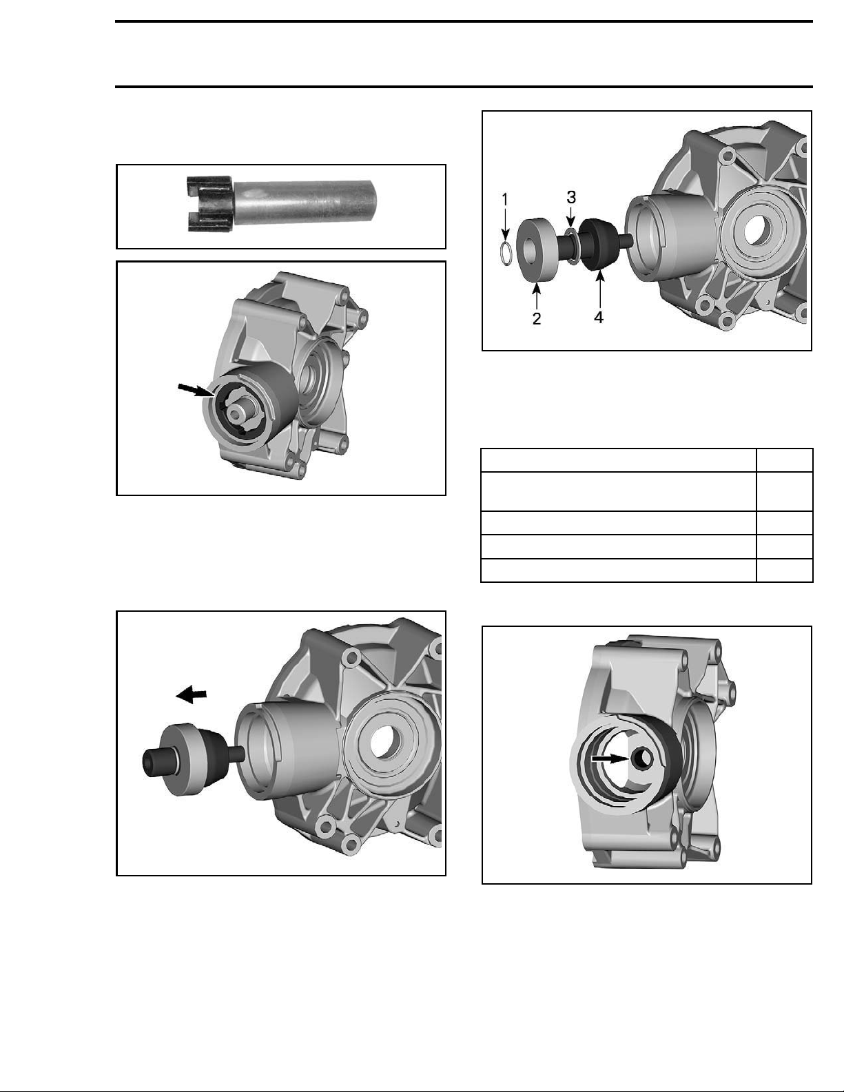
Unscrew the pinion nut. Use the SPANNER
SOCKET (P/N 529 035 649)
529035649
.
Section 07 DRIVE SYSTEM
Subsection 03 (REAR DRIVE)
vmr2015-052-011_a
1. O-ring
2. Ball bearing
3. Pinion gear shim
4. Pinion gear
The pinion gear and bearing can be easily removed
using the following suggested tool:
vmr2015-052-009_a
NOTE: The pinion nut is left hand threaded. Unscrew by turning clockwise.
Remove the bearing along with the pinion gear.
Be careful to keep track of shims. Discard bearing.
PART QTY
Pipe: 83 mm (3-1/4 in) diameter x 127 mm
(5 in)
Threaded rod: M10 x 1.25 x 178 mm (7 in)
M10 x 1.25 nut 3
Flat bar
Remove and discard the needle bearing.
1
1
1
vmr2015-052-010_a
vmr2015-052-012_a
Rear Final Drive Assembly
Adjustment is required when any of the following
part is changed.
– Pinion gear
– Ring gear
– Housing.
As a preliminary setup, install shims according to
the following table.
vmr2015-052 623
Page 14
Section 07 DRIVE SYSTEM
Subsection 03 (REAR DRIVE)
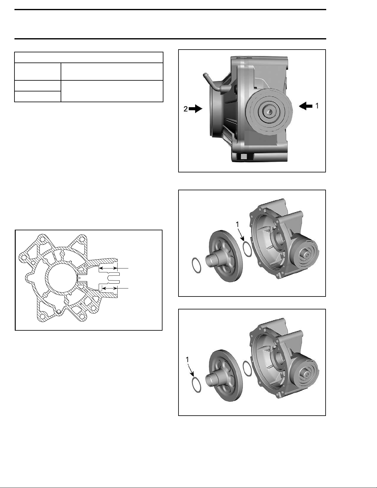
RECOMMENDED SH
PINION GEAR
BACKLASH
PRELOAD
See procedure for pinion gear
(as a p re lim in ary adju stm e nt)
IM THICKNESS
shim thickness
0.5 mm (.02 in)
Procedure for pinion gear shim thickness:
1. Remove the old pinion gear and install the new
one without the ball bearing. The new pinion
will be located at the "zero" location.
2. Measure the
face of the g
distance "A" between outside surear case and the shim surface of
pinion.
3. Measure the distance "B" between outside surface of the gear case and the bearing shoulder
of the gear case.
4. The shim thicknesss will be "A-B-0.53 mm
(.021 in)".
5. Select the
the thick
good combination of shim to match
ness calculated on step 4.
vmr2015-052-015_a
1. Backlash side
2. Preload side
vmr2015-052-016_a
A
B
vmr2015-052-004_a
1. Backlash shim
vmr2015-052-004_b
1. Preload shim
Prior to finalizing assembly, proceed in this order:
– Temporarily assemble final drive using recom-
mended torques.
– Do not apply thread locker product.
– Do not install a new pinion nut.
624 vmr2015-052
Page 15
Section 07 DRIVE SYSTEM
Subsection 03 (REAR DRIVE)
– Check backlash.
– Check preload.
Ring Gear
The installation is the reverse of the removal procedure. However, pay attention to the following:
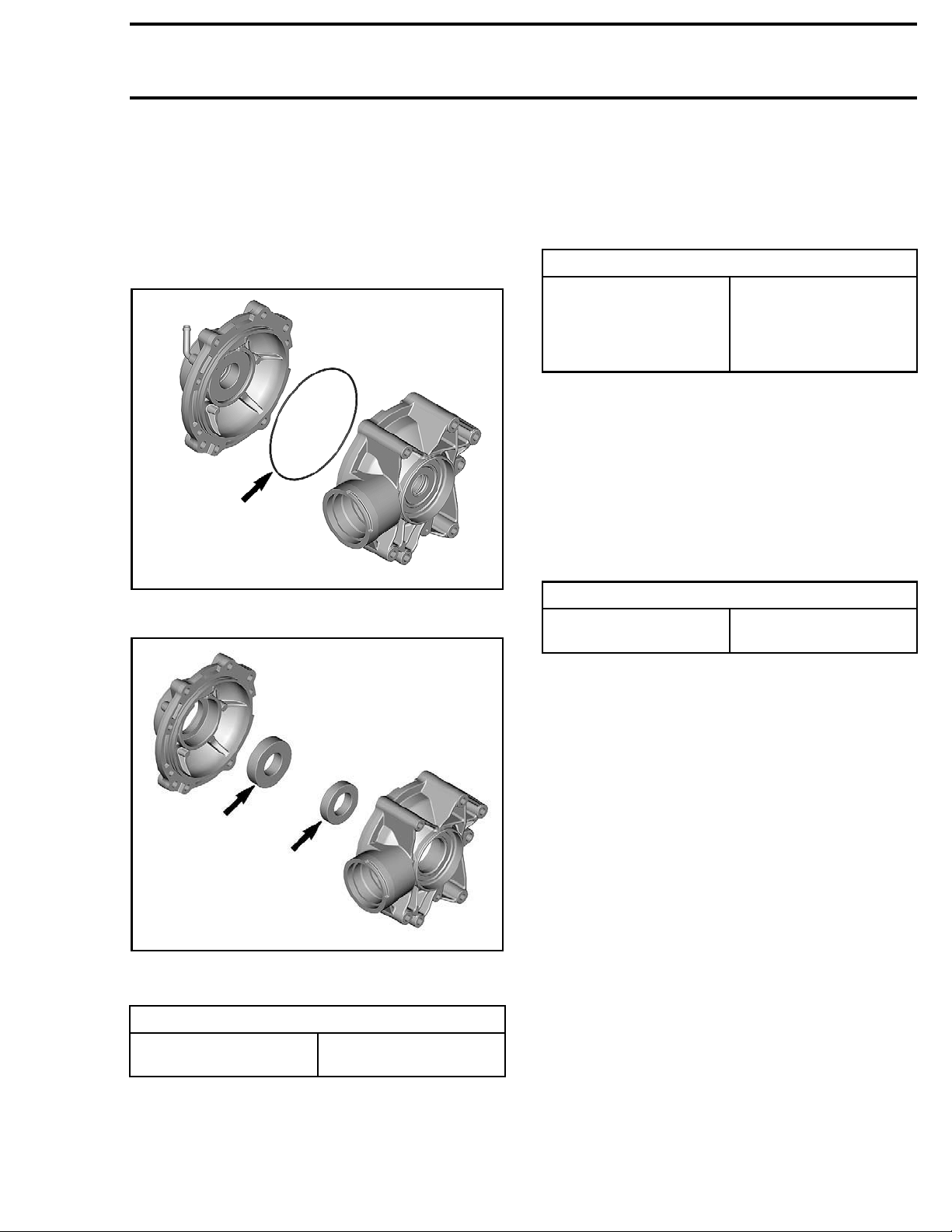
Check condition of seal. Replace if damaged.
vmr2015-052-013_a
Install N
EW bearings.
Install the shim(s) then a NEW ball bearing.
install a NEW O-ring.
Apply
LOCTITE 277 (P/N 293 800 073) to pinion nut.
Install and tighten the p inion nut as per specification.
TIGHTENING TORQUE
180N•m ±15N•m
Pinion nut
(LH THREADS)
Lubricate an
dinstallaNEW oil seal.
(133 lbf•ft ± 11 lbf•ft)
+
LOCTITE 277 (P/N 293
800 073)
Rear Final Drive Installation
The installa
cedure. How
Install the lowest rear final drive retaining screws
first.
Install all screws and nuts prior to tighten.
Tighten nut
Final drive retaining nuts
tion is the reverse of the removal pro-
ever, pay attention to the following:
s to specification.
TIGHTENING TORQUE
90 N•m ± 5 N•m
(66 lbf•ft ± 4 lbf•ft)
vmr2015-052-014_a
Tighten final drive housing screws as per specification.
ENING TORQUE
TIGHT
Final drive housing
scre
on Gear
Pini
ws
32 N•m ± 3 N•m
bf•ft ± 2 lbf•ft)
(24 l
The installation is the reverse of the removal procedure. However, pay attention to the following:
Install a NEW needle bearing.
Refill the final drive with recommended oil. Refer to
PERIODIC MAINTENANCE PROCEDURES
subsection.
vmr2015-052 625
 Loading...