

Page 1
Subsection 01 (POWER DISTRIBUTION AND GROUNDS)
POWER DISTRIBUTION AND GROUNDS
GENERAL
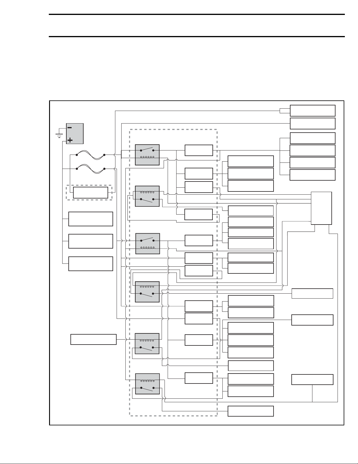
POWER DISTRIBUTION DIAGRAM
DPS2
COMMUNICATION
CONNECTOR DB-5
BAT
16 awg
FL-1
16 awg
FL-2
FUSE BOX 2
F3 40A
MAIN
RELAY (R2)
FUEL PUMP
RELAY (R4)
FUSE BOX 1
F4 5A
F5 5A
F6 5A
IGNITION COIL
FUEL INJECTORS
VEHICLE
SPEED SENSOR
GAUGE
COMMUNICATION
CONNECTOR DB-4
DPS1-A
HICA-C
VOLTAGE
REGULATOR/
RECTIFIER
STARTER
SOLENOID
WINCH RELAY
IGNITION SWITCH
ACCESSORIES
RELAY (R3)
FAN RELAY (R1)
HEADLIGHT
RELAY (R5)
BRAKE LIGHT
RELAY (R8)
F15 5A
F7 5A
F8 5A
F9 25A
F10 5A
F11 30A
F12 15A
F14 15A
FUEL PUMP
2WD/4WD SWITCH
WINCH SWITCH
POSITION LIGHTS
(OUTLANDER EUROPE)
ECM (WAKE UP)
IGNITION SWITCH
CLOCK / HAZARD
HORN / FLASHERS
(EUROPE)
COMMUNICATION
CONNECTOR (DB-6)
12 V POWER OUTLET
DC OPTION
CONNECTOR (DC3)
HEADLIGHTS
DC OPTION
CONNECTORS (DC5/DC6)
TAILLIGHTS /
LICENSE PL
ECM
FAN MOTOR
POSITION LIGHTS
(RENEGADE EUROPE)
BRAKE SWITCH
BRAKE LT PR
vmr2016-132-001_aen
vmr2016-132 1
Page 2
Subsection 01 (POWER DISTRIBUTION AND GROUNDS)
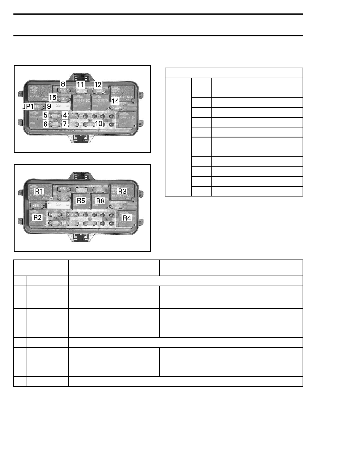
FUSE BOX 1
FUSE IDENTIFICATION
vmr2012-028-006_g
FUSES
vmr2012-028-006_h
RELAYS
Fuse
4
5
5A
5A
65A
7
5A
85A
925A
10 5 A
11
30 A
12 20 A
14
15
20 A
5A
JP1 Jumper 1 (or 20 A fuse)
RELAY
IDENTIFICATION
R1
Cooling fan See
RELAY STATE (ON) RELAY STATE (OFF)
When ignition key is turned ON
R2
Main
AND
Run/Stop switch is set to RUN
Accessories
R3
R4
R5
R8
Fuel pump
Headlights
Brake lights
Same as main relay
Same as main relay
COOLING SYSTEM
Approximately 30 seconds after ignition
When ignition key is turned OFF
When engine speed is less than
1000 RPM for at least 50 minutes
FUEL TANK AND FUEL PUMP
See
When ignition key is turned OFF
When engine speed is less than
1000 RPM for at least 50 minutes
See
BRAKES
key is turne d OFF
OR
OR
2 vmr2016-132
Page 3
Subsection 01 (POWER DISTRIBUTION AND GROUNDS)
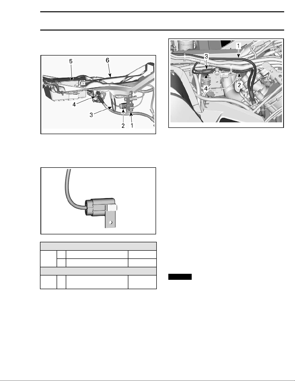
FUSE LINKS AND FUSE BOX 2
vmr2016-132-002_a
LOCATION OF FUSE LINKS AND FB2
1. Connector support (right side of vehicle)
2. Fuse box 2
3. Fuse links 1 and 2
4. Starter solenoid
5. Battery
6. Battery support
vmr2015-131-001_a
TYPICAL - RH
1. Battery ground
2. Engine ground
3. DPS ground
4. Wiring harness ground
SIDE
PROCEDURES
vmr2015-044-004_a
FUSE BOX 2
FUSE LINK IDENTIFICATION
Fuse
links
Fuse 3
1
2 Fan/ac cessories 16 awg
FUSE IN FUSE BOX 2 IDENTIFICATION
(dynamic power steering)
Main 16 awg
DPS
40 A
GROUNDS
All grounds are grouped at the same location on
RH side of frame.
TESTING A FUSE LINK
Measure th
box). Refe
If no voltage is measured, carry out the following:
– Remove the
panel.
– Grab each end of the fuse link and gently pull in
opposite directions.
If the fus
and break
NOTE: Failure of a fuse link is usually due to a severe overload (or short circuit) between the fuse
link and the load it protects (the fuse box).
e fuse link output voltage (at the fuse
rtothe
WIRING DIAGRAM
.
right side panel and extension
e link is open, the insulator should stretch
where the link has failed.
REPLACING A FUSE LINK
NOTICE
to find and repair the cause of the failure.
The gaug
color of
Be sure t
link.
–blue=18awg
– black = 16 awg
–gray=1
Before replacing a fuse link, be sure
e o f the fuse link can be identified by the
its insulator, and by an identification label.
o replace a fuse link by an identical fuse
4awg
vmr2016-132 3
Page 4
Subsection 01 (POWER DISTRIBUTION AND GROUNDS)
vmr2016-132-003_a
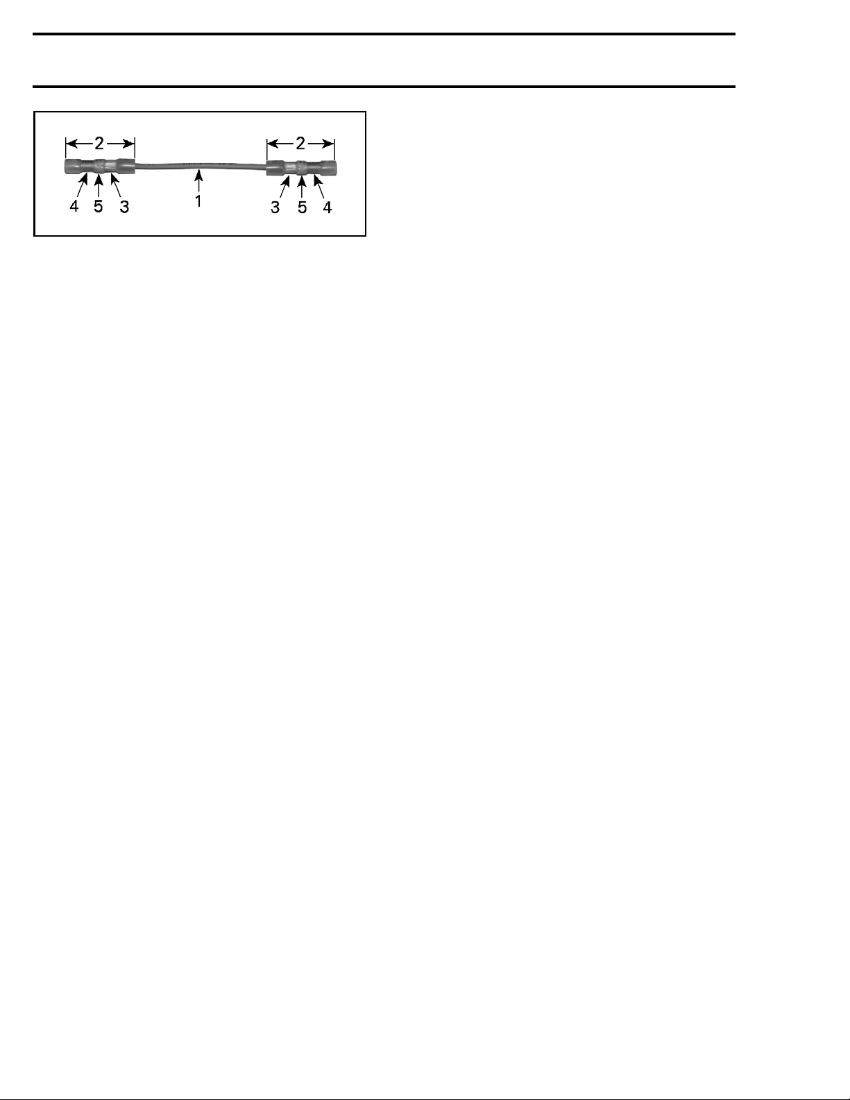
PRE-ASSEMBLED REPLACEMENT FUSE LINK
1. Insulatedfuselinkwire
2. Butt end terminal
3. Terminal factory c rimped on fuse link
4. Crimp here when installing in circuit
5. Solder ring
1. Disconnect the battery.
2. Cut the circuit wiring as close as possible to the
fuse link terminals.
3. Remove 8 mm (5/16 in) of insulator from the
ends of the circuit wiring.
4. Insert the circuit wire end in the link terminal
making sure the wire end bottoms out in the
center of the terminal.
5. Crimp the terminal on the bare wire.
6. Using a heat gun, carefully heat the link terminal until the solder ring has melted into the
wiring, and the terminal insulator has shrunk
tightly around the terminals and wire insulators.
7. Reconnect the battery.
4 vmr2016-132
 Loading...