

Page 1
Page 2

Page 3
1. Read all of these instructions.
2. Save these instructions for later use.
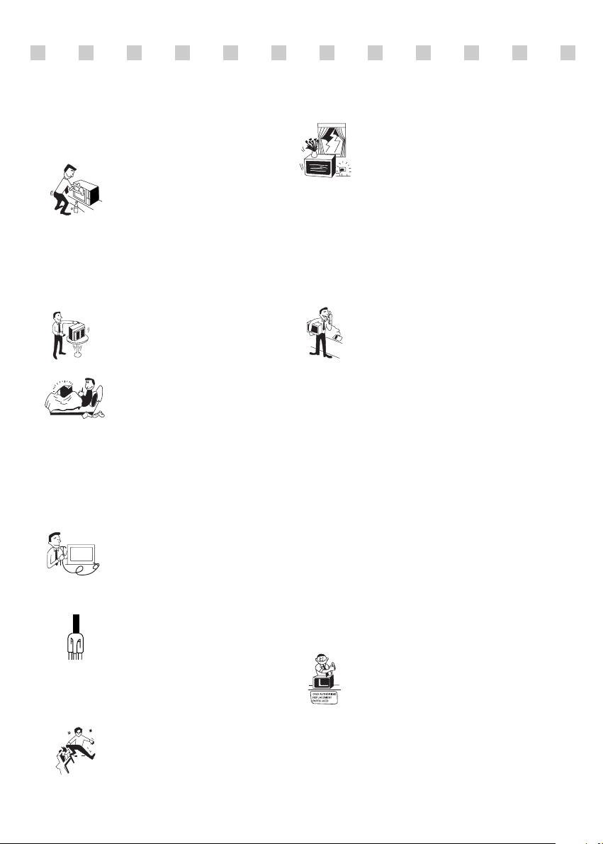
3. Unplug this monitor from the
wall outlet before cleaning. Do not
use liquid cleaners or aerosol
cleaners. Use a damp cloth for
cleaning.
4. Do not use attachments not recommended by
the monitor manufacturer as they may cause
hazards.
5. Do not use this monitor near water, e.g., near a
bathtub, washbowl, kitchen sink, or laundry tub,
in a wet basement, or near a swimming pool, etc.
6. Do not place this monitor on an
unstable cart, stand, or table. The
monitor may fall, causing serious
injury to a child or adult, and
serious damage to the appliance.
7. Slots and openings in the
cabinet and the back or bottom are
provided for ventilation, to ensure
reliable operation of the monitor,
and to protect it from overheating.
These openings must not be blocked or covered.
The openings should never be blocked by
placing the monitor on a bed, sofa, rug, or other
similar surface. This monitor should never be
placed near or over a radiator or heat register.
This monitor should not be placed in a built-in
installation such as a bookcase unless proper
ventilation is provided.
8. This monitor should be operated
only from the type of power source
indicated on the marking label. If
you are not sure of the power
supplied to your home, consult
your monitor dealer or local power company.
9. This monitor is equipped with a
3-wire grounding-type plug, That
is, a plug having a third
(grounding) pin. This plug will
only fit into a grounding-type
power outlet. This is a safety feature. If you are
unable to insert the plug into the outlet, contact
your electrician to replace your obsolete outlet.
Do not defeat the purpose of the grounding-type
plug.
10. Do not allow anything to rest
on the power cord. Do not locate
this monitor where the cord will be
abused by people walking on it.
11. Follow all warnings and instructions marked
on the monitor.
IMPORTANT SAFEGUARDS
12. For added protection for this
monitor during a lightning storm,
or when it is left unattended and
unused for long periods of time,
unplug it from the wall outlet. This
will prevent damage to the monitor and/or the
computer due to lightning and power line surges.
13. Do not overload wall outlets and extension
cords as this can result in fire or electric shock.
14. Never push objects of any kind into this
monitor through cabinet slots, as they may touch
dangerous voltage points or short out parts that
could result in a fire or electric shock. Never spill
liquid of any kind on the monitor.
15. Do not attempt to service this
monitor yourself, as opening or
removing covers may expose you
to dangerous voltages or other
hazards. Refer all servicing to
qualified service personnel.
16. Unplug this monitor from the wall outlet and
refer servicing to qualified service personnel
under the following conditions:
a. When the power cord or plug is damaged or
frayed.
b. If liquid has been spilled into the monitor.
c. If the monitor has been exposed to rain or
water.
d. If the monitor does not operate normally by
following the operating instructions. Adjust only
those controls that are covered by the operating
instructions, as improper adjustment of other
controls may result in damage and will often
require extensive work by a qualified technician
to restore normal operation.
e. If the monitor has been dropped or the cabinet
has been damaged.
f. When the monitor exhibits a distinct change in
performance, this indicates a need for service.
17. When replacement parts are
required be sure the service
technician has used replacement
parts specified by the manufacturer
that have the same characteristics as
the original part. Unauthorized substitutions
may result in fire, electric shock, or other
hazards.
18. Upon completion of any service or repairs to
this monitor, ask the service technician to
perform routine safety checks to determine that
the monitor is safe to operate.
Page 4

FEDERAL COMMUNICATIONS COMMISSION
RADIO FREQUENCY INTERFERENCE STATEMENT
NOTE : This equipment has been tested and found to comply with the limits for a
Class A digital device, pursuant to Part 15 of the FCC Rules. These limits are
designed to provide reasonable protection against harmful interference in a residential
installation. This equipment generates, uses and can radiate radio frequency energy
and, if not installed and used in accordance with the instructions, may cause harmful
interference to radio communications. However, there is no guarantee that
interference will not occur in a particular installation. If this equipment does cause
harmful interference to radio or television reception, which can be determined by
turning the equipment off and on, the user is encouraged to try to correct the
interference by one or more of the following measures :
- Reorient or relocate the receiving antenna.
- Increase the separation between the equipment and receiver.
- Connect the equipment to an outlet on a circuit different from that to
which the receiver is connected.
- Consult the dealer or an experienced radio or Monitor technician for help.
CAUTION : Any changes or modifications not expressly approved by the
party responsible for compliance could void the user
’s authority to operate the
equipment.
CANADIAN NOTICE
AVIS CANADIEN
This Class A digital apparatus meets all requirements of the Canadian
Interference-Causing Equipment Regulations.
Cet appareil numérique de la Class A respecte toutes les exigences du
Règlement sur le matériel brouilleur du Canada.
WARNING: FOR CONTINUED SAFETY, REPLACE POWER ADAPTOR
ONLY WITH MANUFACTURER'S RECOMMENDED MODELS
Page 5

CONTENTS
CONTENTS
Introduction ............................................................................. 1
Product Features ................................................................. 2
Remote Control ...................................................................... 3
Setup ......................................................................................... 5
Stand Assembling Procedures ............................................ 5
Connection ............................................................................... 7
Operation & Adjustment ....................................................... 8
OSD Function .........................................................................13
Specifications ......................................................................... 21
Factory Preset Timings ......................................................... 23
Monitor Rotation .................................................................. 24
Changing the Stand ............................................................... 25
Troubleshooting ..................................................................... 28
Page 6

English - 1
This manual explains how to correctly install, operate and get the
best performance from your monitor. Please read this user’s
guide carefully before installing your monitor, then keep it near
your monitor for quick reference.
First, please check that the contents of the box corresponds with
the following checklist :
• TFT LCD Monitor
• Power cord
• AC Adaptor
• User's guide
• Remote Controller (Optional)
• 15 pin signal cable (Optional)
• Audio Cable (Optional)
• RCA Cable (Optional)
• HDMI Cable (Optional)
If any item is missing or damaged, please contact your dealer.
Please keep the box and packing materials so that you may
properly store or transport your monitor.
INTRODUCTION
INTRODUCTION
Page 7
English - 2
PRODUCT FEATURES
The monitor is designed for use in a small work area or for
those who need more work space on the desk.
The convenient and user-friendly on-screen display allows for
easy and accurate adjustments of screen size, position and
screen color.
The monitor complies with the VESA Display Data Channel
(DDC) specification for Plug and Play compatibility.
Advanced microcircuitry makes setup and configuration fast
and effortless.
The monitor features Advanced Color Controls for fine-tuning
to meet your own personal tastes or application requirements.
Use the on-screen controls to adjust the color temperature,
RGB gain value for the best possible screen color and intensity.
Press the menu button and activate the Self-Diagnosis menu to
determine whether your monitor is functioning normally, not
receiving a signal or is receiving a signal that is out of scanning
range.
Activate the higher refresh rates of the monitor to stabilize the
screen and eliminate the annoying flicker that contributes to
eye-strain and headaches.
The monitor supports the optimal display performance with
1280x1024 at 75Hz.
The monitor can be connected to various types of video devices
with supporting video input signals like Composite
video(CVBS), Seperate video.
The internal stereo speakers make the end user enjoy audio
sound.
Page 8
English - 3
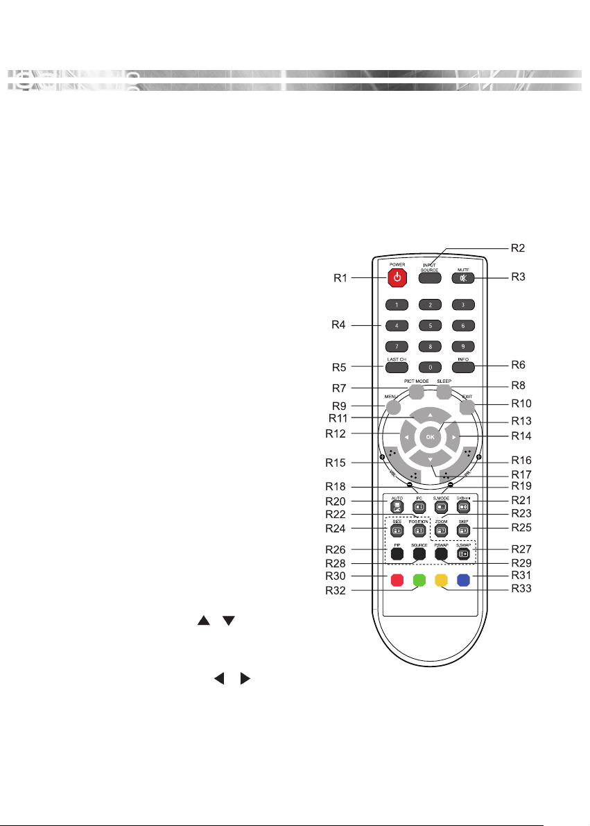
REMOTE CONTROL
REMOTE CONTROL
R1 POWER
·Turns the set on from stand-by or off
to Stand-by mode.
R2 INPUT SOURCE
·Select the signal source from the
multiple input sources.
R3 MUTE
·Turns the sound on and off (Optional)
R4 NUMBER Button
·Not used.
R5 LAST CH
·Not used.
R6 INFO
·Information display.
R7 PICT MODE
·Select the picture mode.
R8 SLEEP
·Sets the sleep timer.
R9 MENU
·Display a main menu.
R10 EXIT
·Turns the OSD window off and moves
from sub Menu to top menu in the
OSD window.
R11 / R17 UP/DOWN
/ Button
·
Press UP/DOWN button to get into
Fuction menu.
R12 / R14 LEFT/RIGHT / Button
·Press LEFT/RIGHT Button to adjust the
volume. (Optional)
Page 9
English - 4
Inserting batteries into the Remote Control unit
To load the batteries turn the remote control handset over and open the
battery compartment. Insert the batteries (2x 1.5v type R03 or AAA). Make
sure that the polarity matches with the (+) and (-) marks inside of the battery
compartment.
Note : To avoid damage from possible battery leakage, remove the batteries
if you do not plan to use the remote control handset for an extended
period of time.
R13 OK
·Select menu items.
R15 VOL +/-
·Adjust the sound level (Optional)
R16 PR +/-
·Not used.
R18 PC
·Select the VGA mode directly
R19 S MODE
·Choose different preset sound
mode or your own customized
sound. (Optional)
R20 AUTO
·Choose automatically the proper
horizontal Position and vertical
position & size of the screen
image. (VGA MODE ONLY)
R21
·Not used.
R22 POSITION
·Select the position of PIP display.
(Optional)
R23 ZOOM
·Select the Screen format
(CAM/HDMI mode only)
R24 SIZE
·
Select the size of PIP display. (Optional)
R25 SKIP
·Not used.
R26 PIP
·Activate or cancel the PIP function.
(Optional)
R27 S. SWAP
·Change the sound source of the
main or sub display.(Optional)
R28 SOURCE
·Select the signal source of the sub
display. (Optional)
R29 P. SWAP
·Change the picture of the main or
sub display. (Optional)
R30, R31,R32,R33
·Not used.
Page 10
English - 5
SETUP
SETUP
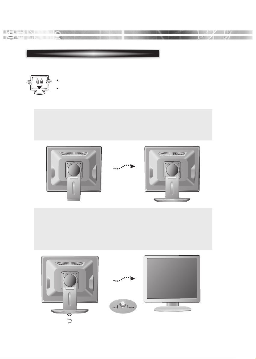
Stand Assembling Procedures(Case#1)
The monitor is packed with stand and main body separated.
Please join the stand with the main body before use.
1. Put some smooth pad or cloth on the level surface and place the
monitor on it with the face downward.
2. Join the stand with the metal protrusion from the bottom of the
monitor’s main body.
3.
Tighten the screw fully at the bottom of the stand by turning it
clockwise three to four turns.
4. After fully tightening the screw, bend the knob of the screw onto the
bottom of the stand.
Caution : Incomplete tightening of the screw may cause the monitor unstable.
Page 11
English - 6
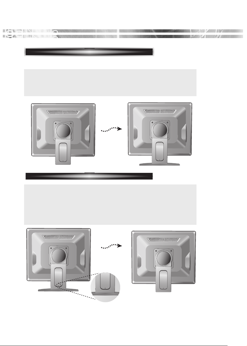
Stand Assembling Procedures(Case#2)
Stnad Disassembling Procedures
1. Put some smooth pad or cloth on the level surface and place the
monitor on it with the face downward.
2. Insert the protrude of stand thoroughly into pedestal.
Stnad Disassembling Procedures
1. Put some smooth pad or cloth on the level surface and place the
monitor on it with the face downward.
2. In order to detach pedestal, press the groove on the back of
protrude connected to the body, using an object with sharp end.
(Note that fixation spot can be broken with too much force)
Page 12
English - 7
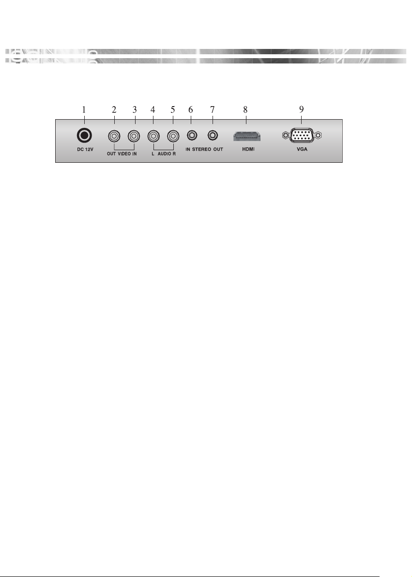
CONNECTION
1. DC 12V Input
2. VIDEO OUT
Composite signal output
3. VIDEO IN
Composite signal input
4. AUDIO L
Audio signal input left
5. AUDIO R
Audio signal input right
6. PC Stereo Input
7. Head Phone Out
8. HDMI
HDMI signal input
9. VGA
RGB signal input
Page 13

English - 8
OPERA
OPERA
TION & ADJUSTMENT
TION & ADJUSTMENT
CONTROL PANEL (Case #1)
POWER Indicator
1
SOURCE
MENU
5
Turns the OSD window on.
Turns the OSD (On-Screen
Display) window off and moves
from sub menu to top menu in
the OSD window.
Switches the monitor on
and off.
POWER
Up Arrow - Auto Adjustment
Down Arrow
Right Arrow - Volume
Left Arrow - Volume
2
Shows both normal operation and power management status with
power indicator light.
*
( )
6
Primary Function: Automatically
adjusts the display to the most
optimal setting possible.(VGA
MODE)
Secondary Function: Allows
forVertical scrolling in the OSD
Menu and to INCREASE the
value of the selected menu
function.
3
Selects menu.
Primary Function : Used to
INCREASE the volume.
Secondary Function:Moves
cursor to the right in the OSD
window and increases the
value of any selected menu.
( )
*
7
Allows for Vertical scrolling in
the OSD Menu, and to
DECREASE the value of the
selected sub menu function.
8
Used to select from different
input sources. Press the UP or
DOWN arrow to scroll
through the available sources,
and press LEFT or RIGHT
arrow to confirm selection.
HOT KEY
( )
*
( )
*
4
Selects menu.
Primary Function: Used to
DECREASE the volume.
Secondary Function:Moves
cursor to the Left in the OSD
window and decreases the
value of any selected menu.
( )
*
Page 14

English - 9
CONTROL PANEL (Case #2)
POWER Indicator
1
SOURCE
MENU
5
Turns the OSD window on.
Turns the OSD (On-Screen
Display) window off and moves
from sub menu to top menu in
the OSD window.
Switches the monitor on
and off.
POWER
Up Arrow - Auto Adjustment
Down Arrow
Right Arrow - Volume
Left Arrow - Volume
2
Shows both normal operation and power management status with
power indicator light.
*
( )
6
Primary Function: Automatically
adjusts the display to the most
optimal setting possible.(VGA
MODE)
Secondary Function: Allows
forVertical scrolling in the OSD
Menu and to INCREASE the
value of the selected menu
function.
3
Selects menu.
Primary Function : Used to
INCREASE the volume.
Secondary Function:Moves
cursor to the right in the OSD
window and increases the
value of any selected menu.
( )
*
7
Allows for Vertical scrolling in
the OSD Menu, and to
DECREASE the value of the
selected sub menu function.
8
Used to select from different
input sources. Press the UP or
DOWN arrow to scroll
through the available sources,
and press LEFT or RIGHT
arrow to confirm selection.
HOT KEY
( )
*
( )
*
4
Selects menu.
Primary Function: Used to
DECREASE the volume.
Secondary Function:Moves
cursor to the Left in the OSD
window and decreases the
value of any selected menu.
( )
*
Page 15

English - 10
KEY PROCESS
① Press MENU to launch the OSD(On-Screen Display) Main Menu.
② Use Left-Right button to select the menu.
③ Use Down button to select the sub menus.
④ Use Up-Down buttons to select sub-menu function.
⑤ Press SOURCE button, then using left-right buttons you can make
adjustments as necessary
⑥ To exit press MENU.
Page 16

English - 11
HOT KEY
When there is no OSD, if you press this ▲
(UP/AUTO) button, you can use the best
displayperformance fit for a current mode.
Selects signal in order.
VGA - HDMI - CAM
When there is no OSD, you can adjust the
volume directly.
Page 17

English - 12
ADJUSTMENT PROCEDURE
Adjust the CLOCK control.
Perform the
H-POSITION.
Perform the Auto
tracking
Is the H.SIZE proper?
Is the noise displayed on
the screen?
Adjust the CLOCK until
the screen is cleared.
Is the noise displayed on
the screen yet?
Yes
Yes
No
No
End
Yes
Page 18

English - 13
OSD FUNCTION
◈◈
VGA MENU (HDMI)
P I C T U R E
S O U N D
1. Bass
When you select the user mode, adjust the bass
sound.
2. Treble
When you select the user mode, adjust the treble
sound.
3. Balance
Adjust the sound balance of the left and right
speakers.
4. MTS
Not Used
5. Sound Mode
Choose different preset sound mode or your own customized sound.
(Standard/Movie/Music/User)
1. Contrast
Adjust the contrast of image, the difference
between light and dark areas on the screen.
2. Brightness
Adjust the brightness of image.
3. Color Mode
Choose different preset color temperatures or set
your own customized color parameters.
(Normal/Warm/Cool/User)
4. Scale
Select the screen size (HDMI mode only)
5. Auto
Choose automatically the proper horizontal Position and
vertical position & size of the screen image.(VGA mode only)
Page 19

English - 14
G E O M E T R Y
S Y S T E M
1. Sleep Timer
Select time to turn off the monitor.
(Off/15/30/45/60 Minutes)
2. Language
Select language for OSD.
(English/Deutsch)
3. OSD H-Position
Adjust the OSD position of the Display
horizontally
(left or right).
4. OSD V-Position
Adjust the OSD position of the Display vertically
(up or down).
5. OSD Timeout
Adjust the display OSD Menu.
(5~60 Second)
6. OSD Transparency
Adjust the OSD. Transparency
7. Information
Shows the status of the current Display settings.
8. Memory Recall
Reset the screen to the factory preset display settings.
1. H-Position
Adjust the position of the display horizontally
(left or right).
2. V-Position
Adjust the position of the display vertically
(up or down).
3. Clock
Adjust the width (horizontal size) of the Screen
image.
4. Phase
Remove any horizontal noise and clear or sharpen
the image of characters.
Page 20

English - 15
P I P
1. Multi Window
Activate or cancel the PIP function.
2. Sub Source
Select the input source the PIP screen.
(CAM)
3. Size
Select the PIP display size.
(Small/Middle/Large/Double 1/Double 2)
4. Position
Adjust the PIP display position.
(R-Up/R-Down/L-Down/L-Up)
5. Border Color
Select the border color of the PIP display.
(Black/Blue)
6. Sound Swap
Select the sound Swap.
(Main/Sub)
7. Pictuer Swap
Change the main picture and the sub pictures of the PIP.
Page 21

English - 16
◈◈
CAM MENU
P I C T U R E
S O U N D
1. Bass
When you select the user mode, adjust the bass
sound.
2. Treble
When you select the user mode, adjust the treble
sound.
3. Balance
Adjust the sound balance of the left and right
speakers.
4. MTS
Not Used.
5. Sound Mode
Choose different preset sound mode or your own
customized sound.
(Standard/Movie/Music/User)
1. Contrast
Adjust the contrast of image, the difference
between light and dark areas on the screen.
2. Brightness
Adjust the brightness of image.
3. Tint
Adjust the Tint of image.
4. Color
Adjust Color of image.
5. Sharpness
Adjust the display image quality
(if the screen proceed to scaling up).
6. Color Tone
Choose different preset color temperatures or set your
own customized color parameters.
(Normal/Warm/Cool)
7. Picture Mode
Select the picture mode.
(Standard/Movie/Dynamic/User)
8. Screen Format
(Full/Zoom1/Zoom2/Subtitle/4:3/panorama)
Page 22

English - 17
F U N C T I O N
S Y S T E M
1. Sleep Timer
Select time to turn off the monitor.
(Off/15/30/45/60 minute)
2. Language
Select language for OSD.
(English/Deutsch)
3. OSD H-Position
Adjust the OSD position of the Display
horizontally
(left or right).
4. OSD V-Position
Adjust the OSD position of the Display vertically
(up or down).
1. 3D NR.
Reduce the noise in the picture due to poor
reception or poor picture quality.
(Off/Low/Middle/High)
2. MADi
Generation advanced color engine automatic
picture enhancement gives.
(2D/3D)
3. H-Size
Adjust the width (horizontal size) of the Screen
image.
4. V-Size
Adjust the height (vertical size) of the Screen image.
5. H-position
Adjust the position of the display horizontally (left or right).
6. V-position
Adjust the position of the display vertically (up or down).
Page 23

English - 18
P I P
1. Multi Window
Activate or cancel the PIP function.
2. Sub Source
Select the input source the PIP screen.
(VGA/HDMI)
3. Size
Select the PIP display size.
(Small/Middle/Large/Double 1/Double 2)
4. Position
Adjust the PIP display position.
(R-Up/R-Down/L-Down/L-Up)
5. Border Color
Select the border color of the PIP display.
(Black/Blue)
6. Sound Swap
Select the sound Swap.
(Main/Sub)
7. Picture Swap
Change the main picture and the sub pictures of the PIP.
5. OSD Time out
Adjust the display OSD Menu.
(5~60 Second)
6. OSD Transparency
Adjust the OSD. Transparency
7. Information
Shows the status of the current Display settings.
8. Memory Recall
Reset the screen to the Factory Preset Display Settings.
Page 24

English - 19
: Supported
X : Non Supported
PIP TABLE
MAIN
VGA HDMI CAM
VGA - X
HDMI X -
CAM -
SUB
Page 25

English - 20
SELF DIAGNOSIS
If there is no image, the Self Diagnosis screen will be displayed.
Self Diagnosis function checks if the status of the monitor screen
is No Signal, Out of range or None support.
No Signal screen is displayed when the DSub signal connector is connected but the
status of the monitor is on DPMS mode.
Out of Range screen is displayed when the
applied frequency is under or over normal
range.
Normal range
(Non-interlaced mode only)
H : 30 - 80 KHz
V : 56 - 77 Hz
Check cable screen is displayed when the
Analog signal cable is disconnected.
Check cable screen is displayed when the
HDMI signal cable is disconnected.
Page 26

English - 21
SPECIFICA
SPECIFICA
TIONS
TIONS
<17 inch>
Panel Size 17-inch(43.2 cm) diagonal
Pixel Pitch 0.264 x 0.264 mm
Viewing Angle 170°(H)
160°(V)
Contrast Ratio 1000:1(typ)
Brightness 250cd/m2brightness(typ)
Response Time 5ms
Color Filter RGB vertical stripe
Synchronization Horizontal 30 - 80 KHz
Vertical 56 - 77 Hz
Video Bandwidth 140MHz
Max Resolution 1280 x 1024@75Hz
Optimal Resolution 1280 x 1024@60Hz
Colors 16.7 M Colors
Display Area 337.9 mm x 270.3 mm
PC Input Signal Sync H/V separate(TTL)
Video
15 pin mini D-sub(Analog RGB)
HDMI
AV Input Signal VIDEO BNC Input / Output
AUDIO RCA Left + Right Input
Stereo Mini Jack Input & Output
Speaker Max. Output 4W ( Left 2W + Right 2W)
Plug and Play VESA DDC Compatible
Power Source DC 12V, 3.33A
Power Consumption < 30W
Dimension-W x H x D
383(W) x 376(H) x 159 mm(with stand)
383(W) x 321(H) x 65 mm(without stand)
Weight-net/gross
4.6Kg / 6.0 Kg (10.1 / 13.2 Lbs)
Power Saving EPA, VESA DPMS, Nutek Compliant
Tilt Range 5° forward, 30° backward
Operating Temperature 0 ~ 40°C /32 ~ 104°F
Page 27

English - 22
<19 inch>
Panel Size 19-inch(48 cm) diagonal
Pixel Pitch 0.294(H)mm x 0.294(V) mm
Viewing Angle 170°(H)
160°(V)
Contrast Ratio 1000:1(typ)
Brightness 250cd/m2brightness (typ)
Response Time 5ms
Color Filter RGB vertical stripe
Synchronization Horizontal 30 - 80 KHz
Vertical 56 - 77 Hz
Video Bandwidth 140 MHz
Max Resolution 1280 x 1024@75Hz
Optimal Resolution 1280 x 1024 @ 60Hz
Colors 16.7 M Colors
Display Area 376.32(H)mm x 301.056(V)mm
PC Input Signal Sync H/V separate (TTL)
Video 15 pin mini D-sub(Analog RGB)
HDMI
AV Input Signal VIDEO BNC Input / Output
AUDIO RCA Left + Right Input
Stereo Mini Jack Input & Output
Speaker Max. Output 4W(Left 2W+Right 2W)
Plug and Play VESA DDC Compatible
Power Source DC 12V, 3.33A
Power Consumption < 30 W
Dimension-W x H x D
427(W) x 415(H) x 159(D) mm(with stand)
427(W) x 358(H) x 66(D) mm(without stand)
Weight-net/gross 5.4Kg / 7.0Kg (11.9 / 15.4 Lbs)
Power Saving EPA, VESA DPMS, Nutek Compliant
Tilt Range 5° forward, 30° backward
Operating Temperature 0 ~ 40°C /32 ~ 104°F
The LCD panel may have some defective pixels (e.g. slightly light or dark) due to a
characteristic of the LCD panel. But there is no defect in your LCD product itself.
The specification can be changed without any prior notice to improve the quality of the product.
Page 28

English - 23
The LCD Monitor has only Non-interlanced modes without flicker.
VESA MODES
Mode Resolution H.Freq(KHz) V.Freq(Hz) Remark
(dots Xlines)
VGA 640 X 480@60Hz 31.5 60 Non-interlaced
VGA 640 X 480@72Hz 37.9 72 Non-interlaced
VGA 640 X 480@75Hz 37.5 75 Non-interlaced
SVGA 800 X 600@56Hz 35.2 56 Non-interlaced
SVGA 800 X 600@60Hz 37.9 60 Non-interlaced
SVGA 800 X 600@72Hz 48.1 72 Non-interlaced
SVGA 800 X 600@75Hz 46.9 75 Non-interlaced
XGA 1024 X 768@60Hz 48.4 60 Non-interlaced
XGA 1024 X 768@70Hz 56.5 70 Non-interlaced
XGA 1024 X 768@75Hz 60.0 75 Non-interlaced
SXGA 1280 X1024@60Hz 64.0 60 Non-interlaced
SXGA 1280 X1024@75Hz 80.0 75 Non-interlaced
SXGA 1152 X 864@75Hz 67.5 75 Non-interlaced
SXGA 1280 X 960@60Hz 60.0 60 Non-interlaced
Mode Resolution H.Freq (KHz) V.Freq (Hz) Remark
(dots Xlines)
EGA 640 X 350@70Hz 31.5 70 Non-interlaced
DOS 720 X 400@70Hz 31.3 70 Non-interlaced
Mode Resolution H.Freq (KHz) V.Freq (Hz) Remark
(dots Xlines)
VGA 640 X 480@67Hz 35.0 67 Non-interlaced
SVGA 832 X 624@75Hz 49.7 75 Non-interlaced
SXGA 1152 X 870@75Hz 68.7 75 Non-interlaced
Mode Resolution H.Freq (KHz) V.Freq (Hz) Remark
(dots Xlines)
SXGA 1280 X1024@70Hz 74.4 70 Non-interlaced
FFACTOR
ACTOR
Y PRESET TIMINGS
Y PRESET TIMINGS
IBM MODES
MAC MODES
THE OTHERS
Page 29

English - 24
MONIITOR ROT
MONIITOR ROTAA
TIION (OPTIIONAL)
TIION (OPTIIONAL)
Page 30

English - 25
Removing Original Stand(Case#1)
1. 1. Detach the rear cover of the stand with a screwdriver.
2. Remove the four screws connecting the stand and the body and the
stand is disassembled.
Turn off the monitor and pull out the power cable.
Place a cushion or a soft cloth on the floor and put the product on it with
the front of the monitor facing the floor.
CHANGING THE ST
CHANGING THE ST
AND
AND
Page 31

English - 26
Removing Original Stand(Case#2)
1. 1. Detach the rear cover of the stand with a screwdriver.
2. Remove the four screws connecting the stand and the body and the
stand is disassembled.
Turn off the monitor and pull out the power cable.
Place a cushion or a soft cloth on the floor and put the product on it with
the front of the monitor facing the floor.
Page 32

English - 27
ATTACHING THE MONITOR WITH THE ARM-STAND(OPTION)
Tighten up screws at the locations
indicated by arrows.
Support
stand
Surface for
stand
installation
This monitor’s installation surface is compatible with various kinds
of VESA standard stands.
Hole spacing : 100x100 mm
Screw Length : 8~12 mm
Page 33

English - 28
TROUBLESHOOTING
TROUBLESHOOTING
Adjust Clock to set the screen position and adjust
Clock fine until a noise isn’t displayed.
Check if power switch and computer power switch
are in the on position.
Check if the signal cable is correctly connected to
the video card.
Check if the pins of D subconnector are not bent.
Check if the computer is in the power- saving mode.
Check if power switch is in the on position.
Check if the power cord is correctly connected.
Check if the signal cable is suitable to the video card.
Adjust Clock or H&V Center to get the proper
image.
Keep the devices that may cause electrical
interference away from the monitor.
See the FCC information at the front cover of the
manual.
Adjust Contrast and Brightness.
Check the audio cable are correctly connected to the
computer.
Adjust the volume after checking the sound is muted.
Check the audio system in the computer.
Symptom
Picture is jitterd.
No picture.
POWER LED is not
lit.
Image is unstable.
Image is not
centered, too small
or too large.
Picture bounces or a
wave pattern is
present in the
picture.
Picture is blurred.
No sound.
Check
Page 34

English - 29
Adjust the volume on the OSD Menu.
Adjust the volume of the sound card in the computer.
Check if PICTURE mode has been set.
Check if the video terminal is properly connected.
Check if the video cable is correctly connected to the
computer and set to the Funtions on the OSD picture
menu.
Adjust the Color or Tint on the OSD Picture Menu.
Adjust the Sharpness on the OSD Picture Menu.
Symptom
Check
Low sound.
VIDEO screen
cannot
be seen.
No video.
Poor color in the
video.
Grainy picture in
the video.
Page 35

MEMO
MEMO
Page 36

MEMO
MEMO
Page 37

MEMO
MEMO
Page 38

MEMO
MEMO
Page 39

Page 40

S/N:9978641918
 Loading...