

Page 1

Subsection 04 (LUBRICATION SYSTEM)
LUBRICATION SYSTEM
SERVICE TOOLS
Description Part Number Page
ADAPTER HOSE ........................................................................... 529 035 652 ............................................. 5
DISCONNECT TOOL ..................................................................... 529 035 714 ............................................. 5
PRESSURE GAUGE....................................................................... 529 035 709 .............................................5
SERVICE PRODUCTS
Description Part Number Page
LOCTITE 243 (BLUE).................................... ................................. 293 800 060 .......................................7, 11
vmr2016-402 1
Page 2
Subsection 04 (LUBRICATION SYSTEM)
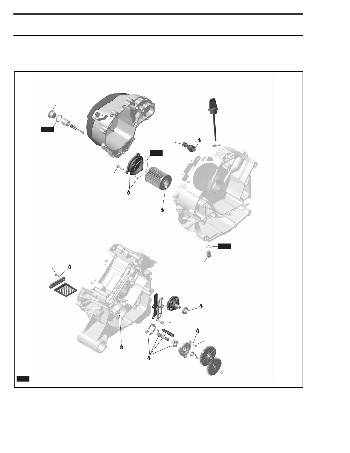
COMPONENTS
570 Engine
20 ± 2 N•m
(15 ± 1,5 lbf•ft)
NEW
6 ± 0,7 N•m
(53 ± 6 lbf•in)
10 ± 1 N•m
(89 ± 9 lbf•in)
Loctite 243
Engine oil
12 ± 1 N•m
(106 ± 9 lbf•in)
NEW
Engine oil
Loctite 243
NEW
20 ± 2 N•m
(15 ± 1,5 lbf•ft)
Engine oil
10 ± 1 N•m
(89 ± 9 lbf•in)
Loctite 243
7 ± 0,5 N•m
(62 ± 4 lbf•in)
Engine oil
Engine oil
= Component must be replaced when removed.
NEW
vmr2015-028-001_a
2 vmr2016-402
Page 3
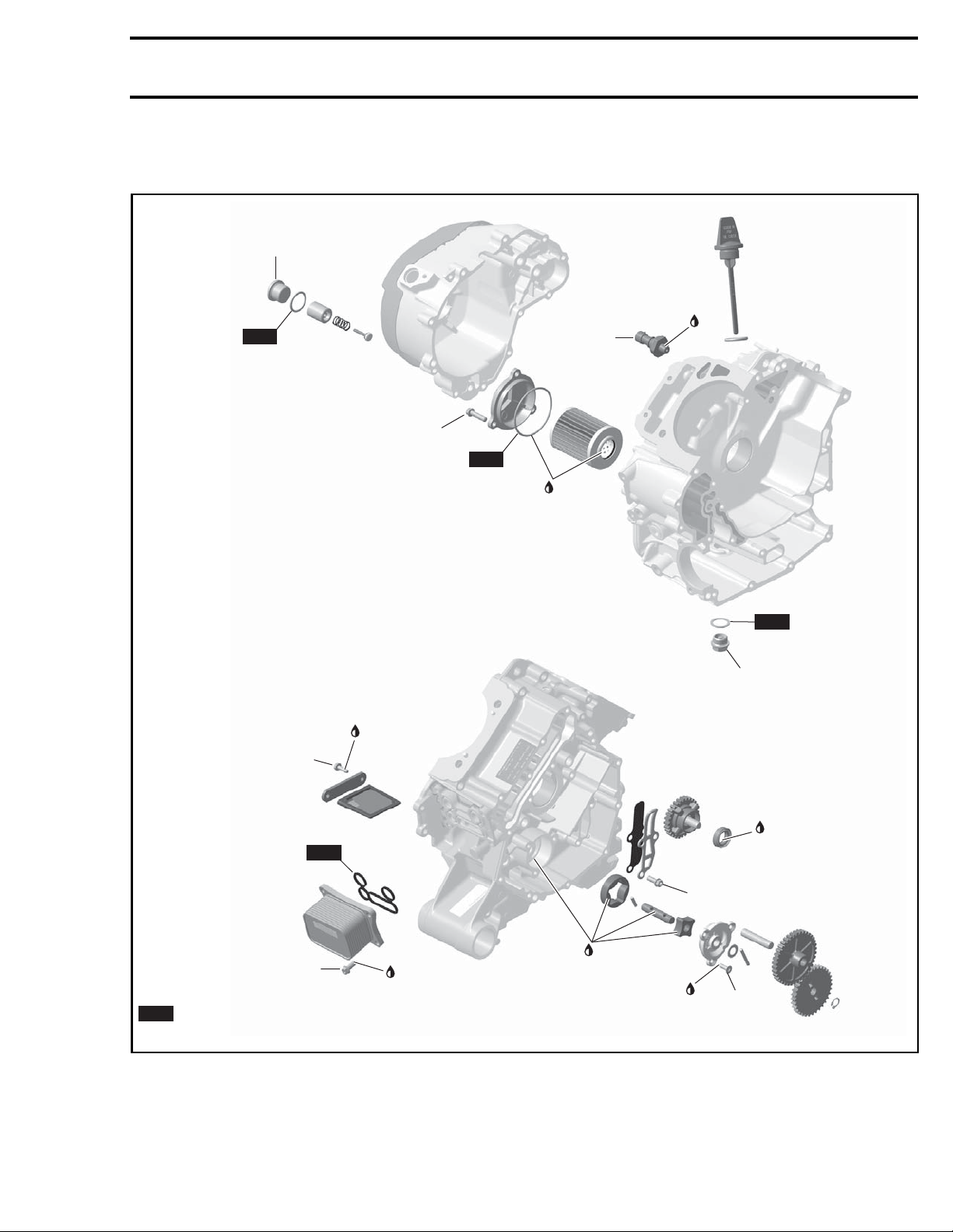
COMPONENTS
850 and 1000R Engines
20 ± 2 N•m
(15 ± 1.5 lbf•ft)
NEW
Subsection 04 (LUBRICATION SYSTEM)
Loctite 243
12 ± 1 N•m
(106 ± 9 lbf•in)
10 ± 1 N•m
(89 ± 9 lbf•in)
NEW
Engine oil
6 ± 0,7 N•m
(53 ± 6 lbf•in)
NEW
8 ± 1 N•m
(70 ± 9 lbf•in)
= Component must be replaced when removed.
NEW
vmr2015-114-001_a
Loctite 243
Loctite 243
Engine oil
Loctite 243
NEW
30 ± 2 N•m
(22 ± 1.5 lbf•ft)
Engine oil
10 ± 1 N•m
(89 ± 9 lbf•in)
7 ± 0,5 N•m
(62 ± 4 lbf•in)
vmr2016-402 3
Page 4
Subsection 04 (LUBRICATION SYSTEM)
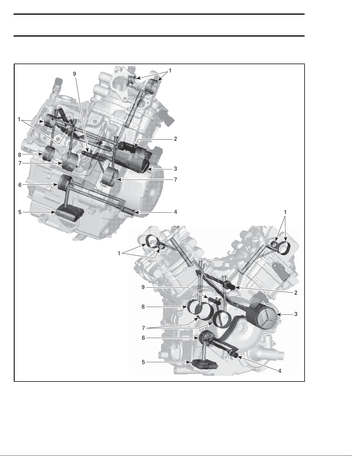
ENGINE LUBRICATION CIRCUIT
vmr2007-033-001_a
1. Camshaft bearings
2. Oil pressure switch
3. Oil filter
4. Oil pressure regulator valve
5. Oil strainer
6. Oil pump
7. Crankshaft main bearings
8. Crankshaft support bearing
9. Connecting rod bearings
4
vmr2016-402
Page 5
Subsection 04 (LUBRICATION SYSTEM)
INSPECTION
TESTING THE ENGINE OIL
PRESSURE
NOTE: The engine oil pressure test should be
done with a warm engine 100°C (212°F) and the
recommended oil.
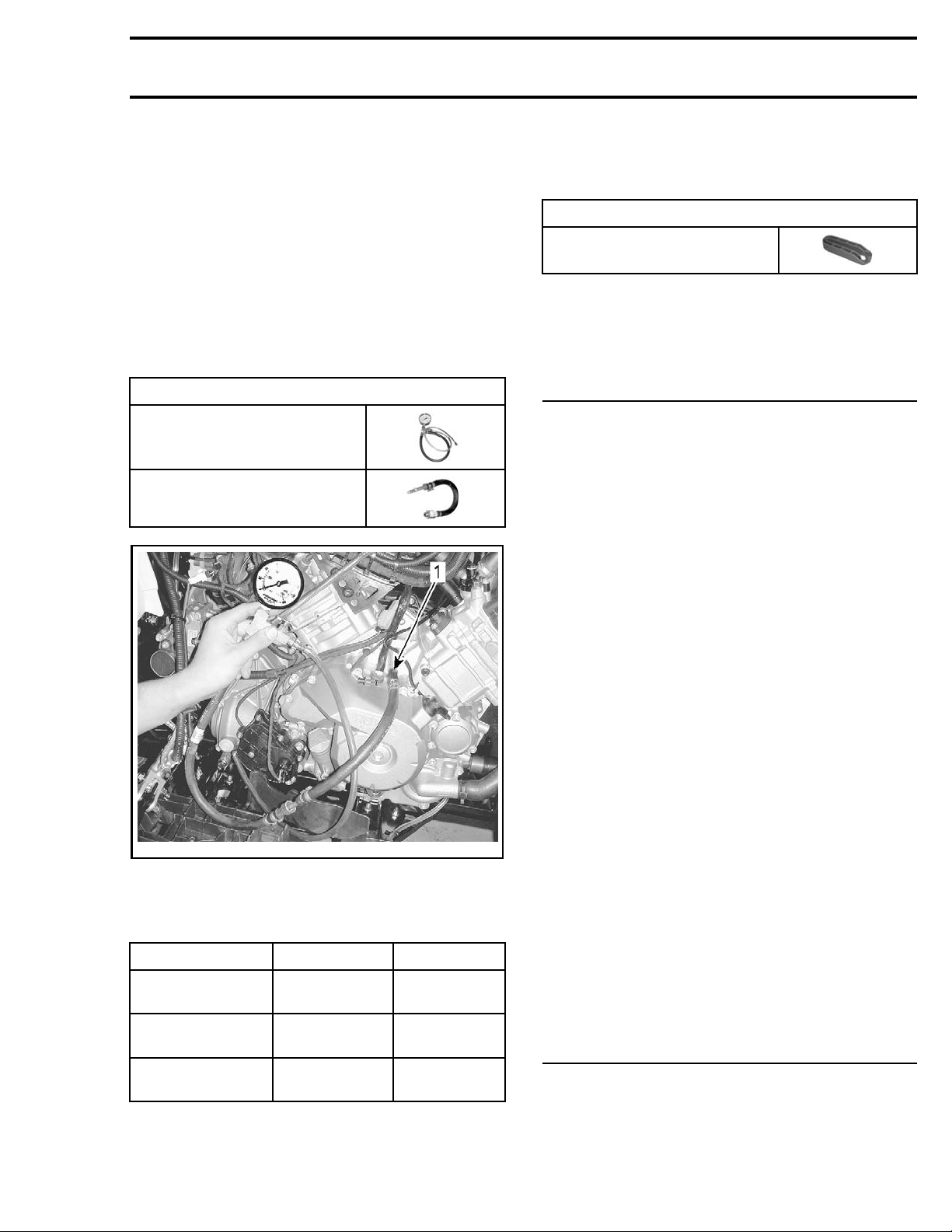
Remove the oil
PRESSURE SWIT
pressure switch. Refer to
in this subsection.
CH
Install the pressure test gauge with the proper
adapter hose in the OPS engine bore.
REQUIRED TOOL
PRESSURE GAUGE
(P/N 529 035 709)
ADAPTER HOSE
(P/N 529 035 652)
OIL
Remove oil pressure gauge and adapter hose.
NOTE: To remove adapter hose from oil pressure
gauge, use the disconnect tool.
REQUIRED TOOL
DISCONNECT TOOL
(P/N 529 035 714)
Reinstall the oil pressure switch and remaining
components.
TROUBLESHOOTING
LOW OR NO OIL PRESSURE
1. Oillevelistoolow.
- Refill engine with recommen ded engine o il. Refer to OIL LEVEL VERIFICATION in the PERIODIC
MAINTENANCE PROCEDURES subsection.
- Check for high oil consumption, refer to HIGH OIL
CONSUMPTION in thisTROUBLESHOOTING.
- Check for engine oil leaks. For leak indicator
hose and leak indicator hole, refer to COOL ING
SYSTEM INSPECTION in the PERIODIC MAINTENANCE PROCEDURES subsection. Repair if
necessary.
vmr2015-028-100_a
TYPICAL
1. Gauge co
nnected in OPS engine bore
The engine oil pressure should be within the following values.
OIL PRESSURE 1250 RPM 6000 RPM
MINIMAL
NOMINAL
MAXIMAL
70 kPa (1
150 kPa
(22 PSI)
250 kPa
(36 PSI)
0 PSI)
300 kPa
(44 PSI)
350 kPa
(51 PSI)
450 kPa
(65 PSI)
If the engine oil pressure is out of specifications,
check the points described in
in this subsection.
ING
TROUBLESHOOT-
2. Use of unsuitable engine oil type.
- Replace engine oil by the recommended engine
oil.
3. Clogged oil filter.
- Replace oil and oil filter at the same time.
4. Defective oil pressure switch.
- Test oil pressure switch, see procedure in this
subsection.
5. Defective or worn oil pump.
- Check oil pump, see procedure in this subsection.
6. Defective engine oil pressure regulator.
- Check engine oil pressure regulator, see procedure in this subsection.
7. Worn plain bearings in crankcase.
- Check plain bearing clearance, refer to BOTTOM
END subsection.
8. Clogged engine oil strainer.
- Clean engine oil strainer, see procedure in this
subsection.
OIL CONTAMINATION
1. Defective water pump seal ring or rotary seal.
- Check for oil or coolant leak from indicator near
water pump, refer to COOLING SYSTEM INSPECTION in the PERIODIC MAINTENANCE
PROCEDURES subsection. Replace seal if necessary.
vmr2016-402 5
Page 6
Subsection 04 (LUBRICATION SYSTEM)
2. Cylinder head or cylinder base gasket leak.
- Retighten cylinder head to specified torque, refer
to TOP END subsection. Replace gasket if tightening does not solve the problem.
3. Engine internal damage.
- Repair engine.
4. Oil cooler gasket leak.
- Replace oil cooler gasket and change engine oil.
HIGH OIL CONSUMPTION
1. Leaking breather oil seal.
- Check if the oil seal of the breather is brittle, hard
or damaged. Refer to BOTTOM END subsection.
2. Valve stem seals worn or damaged.
- Replace valve stem seals.
3. Worn piston rings (blue exhaust smoke).
- Replace piston rings.
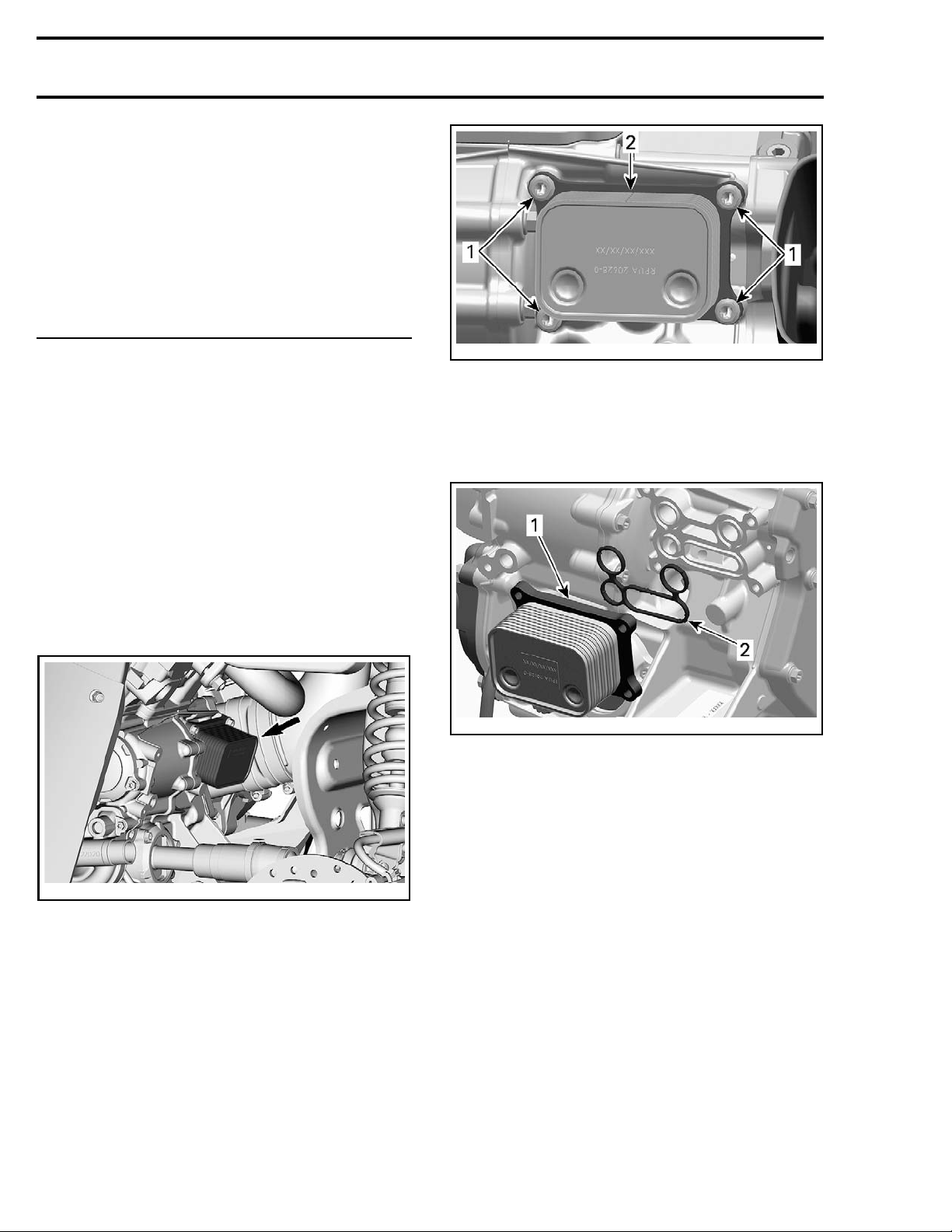
tmr2011-010-006_a
1. Retaining screws
2. Oil cooler
Place rags or towels under oil cooler to catch remaining o il and coolant.
Remove oil cooler a nd discard gasket.
PROCEDURES
OIL COOLER (850 AND 1000R
ENGINES)
Oil Cooler Location
vmr2016-402-001_a
Remov
Refer to
DURES
–Drain
CHANG
– Drain coolant. Refer to
PLACEMENT
Remov
ing the Oil Cooler
PERIODIC MAINTENANCE PROCE-
subsection to:
engine oil. Refer to
E
ENGINE COOLANT RE-
.
e oil cooler retaining screws.
ENGINE OIL
tmr2011-010-007_a
1. Oil coo
2. Gasket
ler
Inspecting the Oil Cooler
Check oil cooler for cracks or other damage.
Replac
e if necessary.
Installing the Oil Cooler
For ins
Pay att
Wipe off any oil and coolant spillage.
Install a NEW gasket.
Refer to
DURES
– Refill engine with recommended oil. See
– Refill and bleed cooling system. See
tallation, reverse the removal procedure.
ention to the following details.
PERIODIC MAINTENANCE PROCE-
ubsection and carry out the following:
s
GINE OIL CHANGE
COOLANT REPLACEMENT
.
.
ENGINE
EN-
6 vmr2016-402
Page 7
Subsection 04 (LUBRICATION SYSTEM)
OIL PRESSURE SWITCH (OPS)
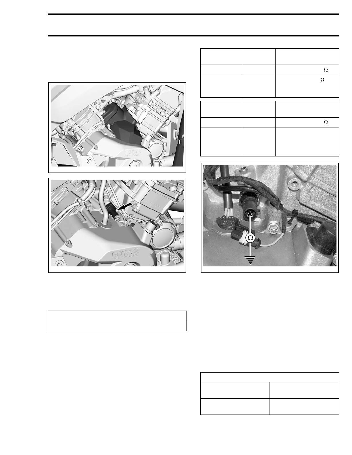
Oil Pressure Switch Access
Remove OPS cover.
vmr2016-402-003
OPS
CONNECTOR
PIN RESISTANCE ( )
1
OPS
CONNECTOR
PIN RESISTANCE ( )
1
ENGINE
Engine
ground
ENGINE ENGINE RUNNING
Engine
ground
ENGINE NOT
RUNNING
Closeto0
(normally closed
switch)
Infinite (open) when
pressure reaches
30 kPa ± 10 kPa
(4.35 PSI ± 1.45 PSI)
vmr2016-402-002_a
Oil Pressure Switch Activation
The oil pressure switch activates when the engine
oil pressure is lower than following specified pressure range.
OIL PRESSURE SWITCH ACTIVATION RANGE
30 kPa ± 10 kPa (4.35 PSI ± 1.45 PSI)
To check the function of the oil pressure switch,
an oil pressure test has to be performed. Refer to
ENGINE OIL PRESSURE
in this subsection.
If the engine oil pressure is good, perform the oil
pressure switch resistance test.
Testing the Oil Pressure Switch
Resistance
Disconnect the connector from the oil pressure
switch.
Check resistance as per following tables.
vmr2006-014-009_a
If resistance values are incorrect, replace the oil
pressure switch.
If the values are correct, check wiring.
Removing the Oil Pressure Switch
Unplug the oil pressure switch connector.
Unscrew and remove oil pressure switch.
Installing the Oil Pressure Switch
Apply required service product on threads of oil
pressure switch.
Tighten oil pressure switch to specification.
TIGHTEN
Service product
Oil pressure switch
ING TORQUE
LOCTITE 243 (BLUE)
(P/N 293
12 N•m ± 1 N•m
f•in ±9lbf•in)
(106 lb
800 060)
vmr2016-402 7
Page 8
Subsection 04 (LUBRICATION SYSTEM)
ENGINE OIL PRESSURE
REGULATOR
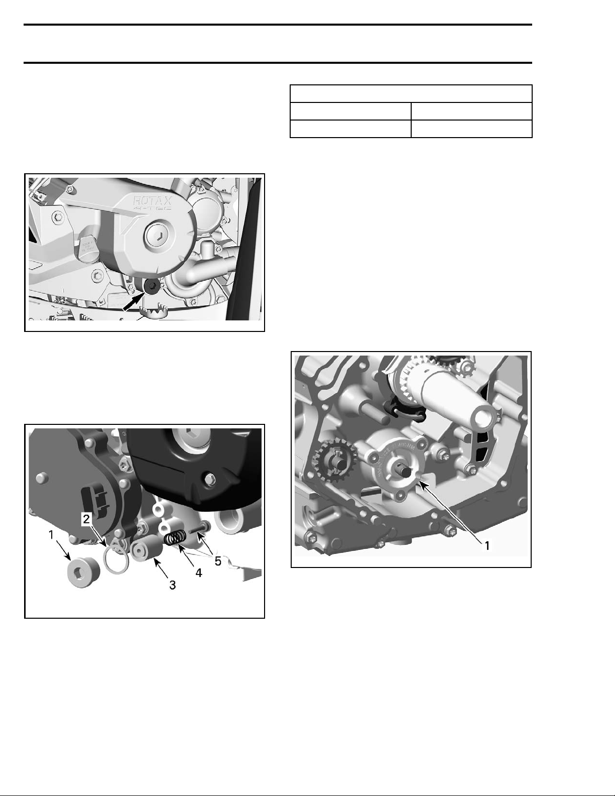
Oil Pressure Regulator Location
The oil pressure regulator is located on the engine
magneto side, integrated in the magneto cover.
vmr2016-402-004_a
NOTE: The oil pressure regulator system works
when the oil pressure exceeds 400 kPa (58 PSI).
Removing the Oil Pressure Regulator
Remove plug screw and pull oil pressure regulator
out.
SPRING FREE LEN
NEW NOMINAL
SERVICE LIMIT
GTH
39 mm (1.535 in)
37 mm (1.457 in)
NOTE: Replace worn or damaged components.
Clean bore and thread in the magneto housing
from metal shavings and other contaminations.
Installing the Oil Pressure Regulator
For installation, reverse the removal procedure.
Pay attention to the following details.
NOTE: At inst
ring of the p l
allation always replace the gasket
ug screw by a NEW one.
OIL PUMP
Oil Pump Location
The oil pump i
(behind PTO c
s located on the engine PTO side
over).
vmr2006-042-009_a
1. Oil pump
Removing the Oil Pump
vmr2015-028-003_a
1. Plug screw
2. Gasket ring
3. Pressure regulator housing
4. Spring
5. Pressure regulator valve
Remove t
the
1. Remove:
–Retain
he PTO cover. Refer to
BOTT
OM END
subsection.
ing ring
– Oil pump gear
Inspecting the Oil Pressure Regulator
Inspect pressure regulator housing and valve for
– Needle pin
– Thrust
washer.
scoring or other damages.
Check spring for free length.
8 vmr2016-402
PTO COVER
in
Page 9
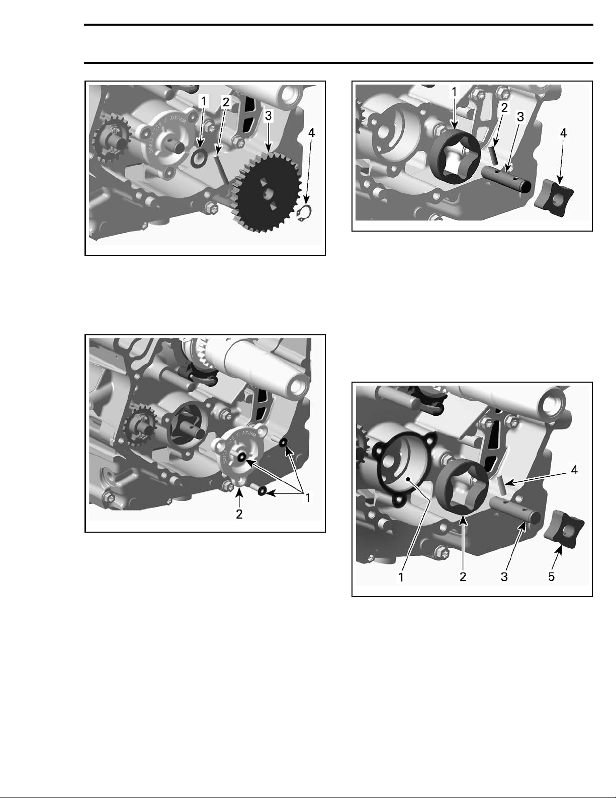
tmr2011-010-011_a
1. Thrust washer
2. Needle pin
3. Oil pump gear
4. Retaining ring
2. Remove oil pump cover screws and pull oil
pump cover out.
Subsection 04 (LUBRICATION SYSTEM)
tmr2011-010-012_a
1. Outer rotor
2. Needle pin
3. Oil pump shaft
4. Inner rotor
Inspecting the Oil Pump
Inspect oil pump and oil pump cover bore for
marks, scratches or other damages. Check for
scratches in crankcase between outer rotor and
oil pump bore. If so, replace damaged parts.
Check oil pump cover for damages and for surface
straightness with a straightedge.
06-042-011_a
vmr20
1. Retaining screws
2. Oil pump cover
3. Remo
4. Remove outer rotor.
ve oil pump shaft with needle pin and in-
otor.
ner r
vmr2006-042-012_a
1. Oil pu
2. Outer rotor
3. Oil pump shaft
4. Need
5. Inner rotor
mp bore
le pin
Check inner rotor for corrosion pin holes or other
damages. If so, replace oil pump shaft assembly.
vmr2016-402 9
Page 10
Subsection 04 (LUBRICATION SYSTEM)
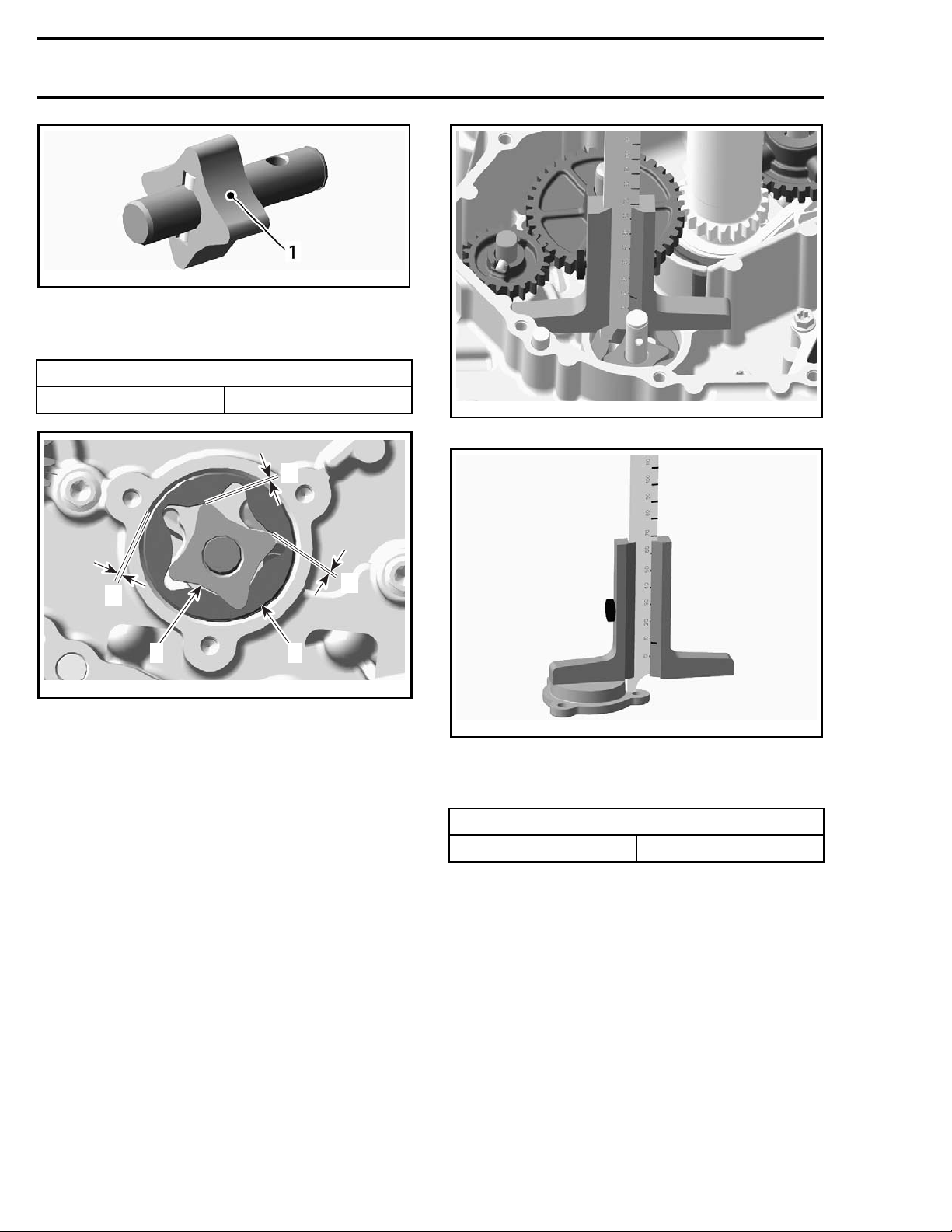
vmr2006-042-013_a
1. Pittings on the teeth
Using a feeler gauge, measure the clearance of
inner and outer rotors as shown.
CLEARANCE OF INNER AND OUTER ROTOR
SERVICE LIMIT
0.25 mm (.0098 in)
A
A
A
2
vmr2006-042-014_a
1. Outer rotor
2. Inner rotor
A. 0.25 mm (.0098 in)
If clearance of i nner and outer rotors exceeds the
tolerance, replace oil pump rotors. Ensure to also
check oil pump cover. If damaged, replace the
complete oil pump assembly.
If clearance between outer rotor and its bore in
crankcase exceeds the tolerance, replace the
complete oil pump rotors and/or the crankcase.
Using a depth gauge, measure the axial clearance
of the oil pump as shown.
1
vmr2006-042-015
OIL PUMP — ME
vmr2006-042-016
OIL PU M P COVER — ME ASUREMENT “B”
ASUREMENT “A”
Substract measurement B from measurement A
to obtain axial clearance.
OIL PUM
SERVICE LIMIT
P AXIAL CLEARANCE
0.20 mm (.008 in)
NOTE: When the axial clearance of the oil pump
assembly increases, the oil pressure decreases.
Installing the Oil Pump
For installation, reverse the removal procedure.
Pay attention to the following details.
NOTE: When installing the oil pump rotors, make
sure both markings are on the outer side.
10 vmr2016-402
Page 11
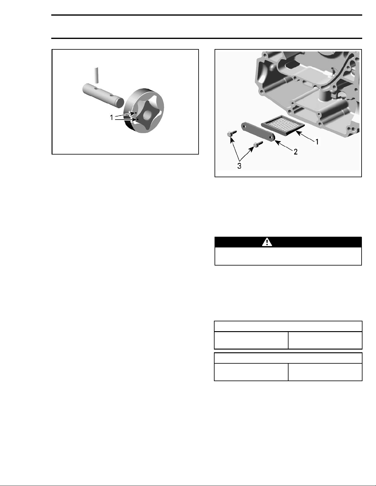
vmr2015-114-005_a
1. Markings
Subsection 04 (LUBRICATION SYSTEM)
After reinstallation of the remaining parts, check
for smooth operation of the oil pump assembly.
Testing the Oil Pump Function
After engine is completely reassembled, start engine and make sure oil pressure is within specifications (refer to
ENGINE OIL PRESSURE
in this
subsection).
ENGINE OIL STRAINER
Oil Strainer Location
The engine oil strainer is located between both
crankcase halves.
Removing the Oil Strainer
Remove engine from vehicle.
Separate crankcase halves. Refer to
subsection.
END
Remove screws and retaining plate.
Pull out engine oil strainer.
BOTTOM
vmr2006-042-017_a
1. Engine oil strainer
2. Retaining plate
3. Screws
Cleaning and Inspecting the Oil
Strainer
Clean engine oil strainer with a part cleaner then
useanairguntodryit.
WARNING
Always wear eye protector. Chemicals can
cause a rash break out and injure your eyes.
Check en
age. Re
gine oil strainer for cracks or other dam-
place if damaged.
Installing the Oil Strainer
The inst
cedure
allation is the reverse of the removal pro-
.
SERVICE PRODUCT
Oil Strainer screws
LOCTITE 243 (BLUE)
(P/N 293 800 060)
TIGHTE
Oil strainer screws
NING TORQUE
6N•m ±0.7N•m
f•in ±6lbf•in)
(53 lb
REED VALVE
The en
preve
the cr
cran
vmr2016-402 11
gine is equipped with a reed valve which
nts accumulation of larger oil quantities in
ankcase. The reed valve i s fitted into the
kcase.
Page 12
Subsection 04 (LUBRICATION SYSTEM)
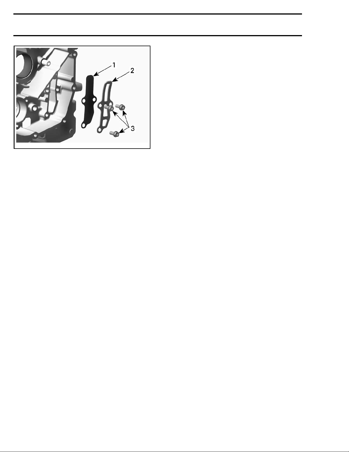
vmr2006-042-018_a
1. Reed valve
2. Stopper
3. Screws
Removing the Reed Valve
Remove:
– Engine from vehicle
–PTOcover(referto
TOM END
subsection)
– Reed valve retaining screws
– Stopper plate
– Reed valve.
PTO COVER
in the
BOT-
Inspecting the Reed Valve
Check reed valve for cracks or other damage.
Replace reed valve if damaged.
Installing the Reed Valve
The installation is the reverse of the removal procedure.
12 vmr2016-402
 Loading...