

Page 1
Subsection 07 (LIGHTS, GAUGE AND ACCESSORIES)
LIGHTS, GAUGE AND ACCESSORIES
SERVICE TOOLS
Description Part Number Page
FLUKE 115 MULTIMETER ............................................................ 529 035 868 ............................................. 9
SERVICE PRODUCTS
Description Part Number Page
DIELECTRIC GREA SE ................................................................... 293 550 004 ............................................. 4
GENERAL
NOTICE
It is recommended to always disconnect the battery when replacing any electric
or electronic parts. Always disconnect battery
exactly in the specified order, BLACK (-) cable
first.
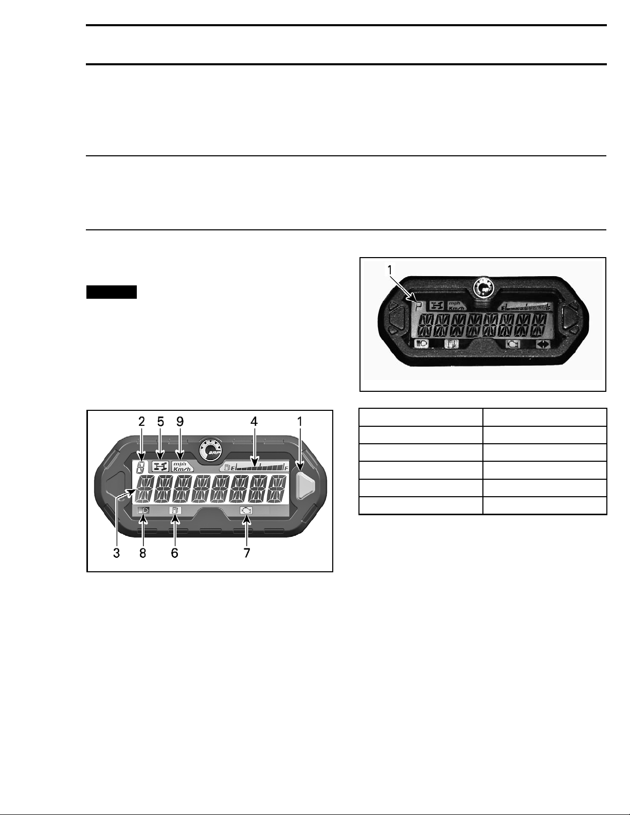
MULTIFUNCTION GAUGE
Multifunction Gauge Description
vmo2013-010-001_a
1. Selector button
2. Transmission position display
3. Main screen
4. Fuel level display
5. 4WD i ndicator lamp
6. Low fuel level indicator lamp
7. Check engine indicator lamp
8. High beam indicator lamp
9. MPH, Km/h indicator lamp
10.Signal lights/hazard lights indicator lamp (CE models)
vmr2007-050-002_d
1. Transmission position
DISPLAY FUNCTION
PPark
R Reverse
NNeutral
H High range
LLowrange
3) Main Screen
The main screen is used to display numerous
functions of the multifunction gauge.
Refer to
MULTIFUNCT
the available displ
ION GAUGE MODES
ay modes.
for
4) Fuel Level Display
Bar gauge continuously indicates the level of fuel
in the fuel tank while riding.
1) Selector Button
The selector button is used to navigate or change
settings in the multifunction gauge.
2) Transmission Position Display
This display will show transmission position.
vmr2016-410 1
Page 2
Subsection 07 (LIGHTS, GAUGE AND ACCESSORIES)
10) Turn signal/Hazard lights Indicator Lamp
When this indicator is ON, it indicates:
– A turn signal is activated, or
– The hazard lights are activated.
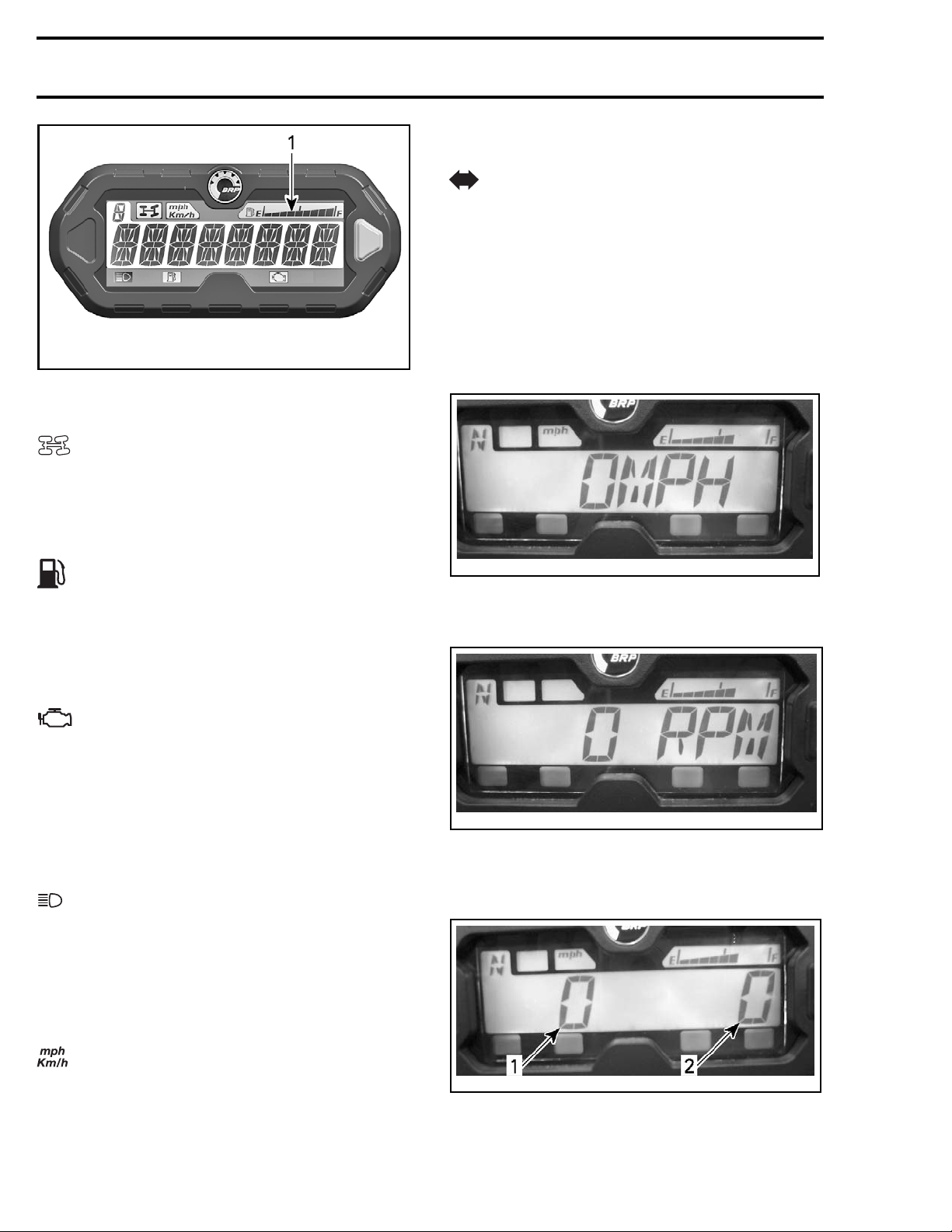
Multifunction Display Modes
Speed Mode
vmo2013-010-001_b
1. Fuel level display
5) 4WD Indicator Lamp
When this indicator is ON, it indicates the 4WD
system is activated.
In this mode, the display shows the speed of the
vehicle either in km/h or in MPH.
6) Low Fuel Level Indicator Lamp
When this indicator is ON, it i ndicates that there is
approximately 5 L (1.3 U.S. gal.) of fuel left in fuel
tank.
7) Check Engine Indicator Lamp
When this indicator is ON, it indicates an engine
fault code, look for a message in the main screen
display.
When this indicator blinks, it indicates that LIMP
HOME mode is activated.
8) High Beam Indicator Lamp
When this indicator is ON, it indicates that high
beam is selected on the headlights switch and
that the ignition key is in the "ON with lights" position.
vdd2008-001-084
RPM Mode
In this mode, the display shows the engine RPM.
vdd2008-001-089
Combine
d Mode
In this mode, the display shows the speed of the
vehicle and the engine RPM.
9) KM/H or MPH Indicator Lamp
The applicable lamp turns on to indicate the active
speedometer unit of display.
2
vdd2008-001-085_a
1. Vehicle speed
2. Engine RPM
vmr2016-410
Page 3
Subsection 07 (LIGHTS, GAUGE AND ACCESSORIES)
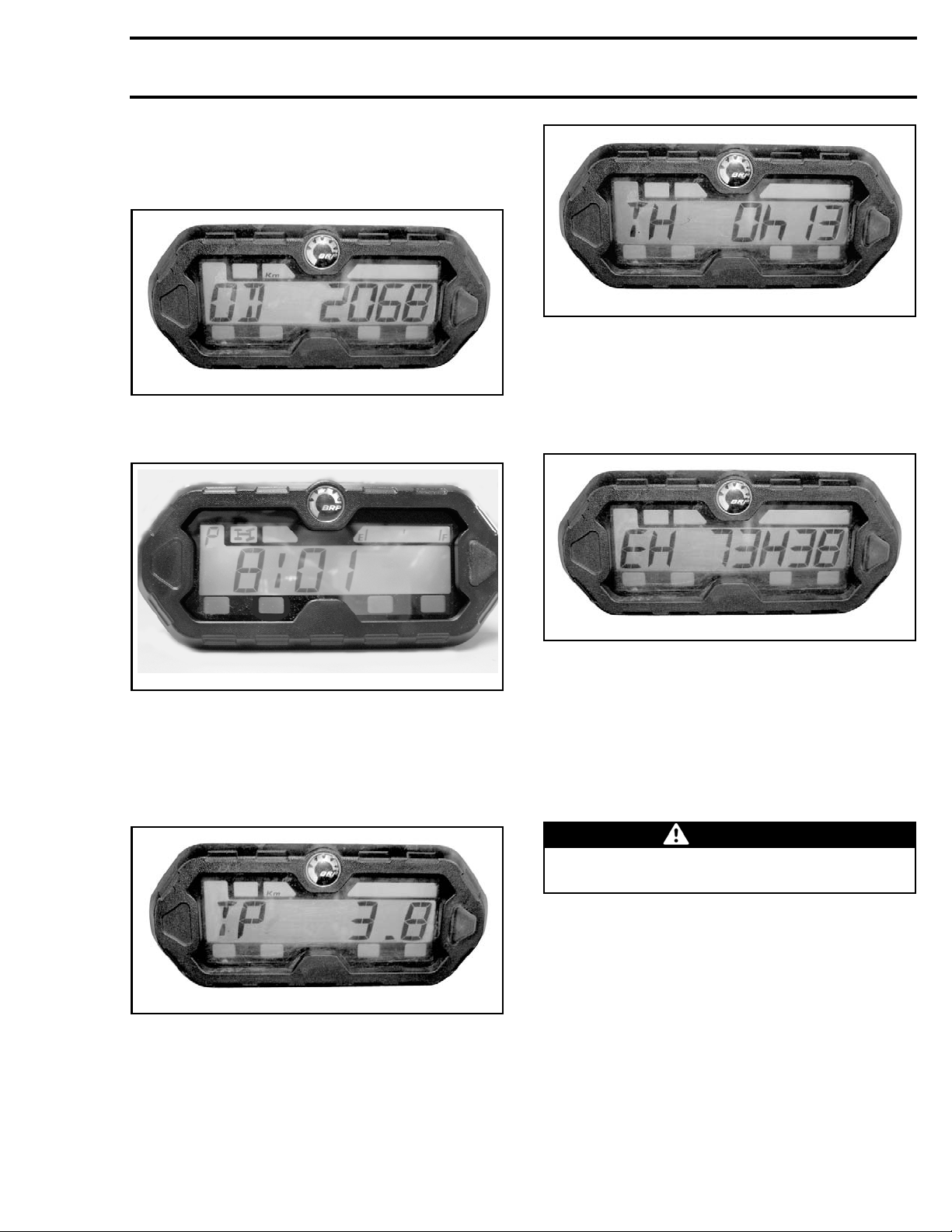
Odometer (OD)
Odometer records the total distance travelled either in miles or kilometers.
vsi2009-018-032
Press and HOLD the selector button for 2 seconds
to reset the hour meter.
vsi2009-018-030
Clock
Shows current time.
008-001
vmo2011-
Refer to
GAUGE SETUP
to set current time.
Trip Meter (TP )
The trip meter records the travelled distance since
it has been reset. Distance travelled is displayed
either in kilometers or miles.
Engine Hour Meter (EH)
The engine h
our meter records engine running
time.
vsi2009-018-033
Message Display Mode
If an abno
sage may s
junction
Refer to
rmal engine condition occurs, a mes-
croll across the main screen in con-
with a pilot lamp.
DIAGNOSTIC AND FAULT CODES
section.
Navigati
ng the L CD Gauge
sub-
WARNING
Never adjust or set functions on the multifunction gauge while riding the vehicle.
Default Display Mode
After vehicle startup, the default display mode is
either:
– Vehicle speed
vsi2009-018-031
Press and HOLD the selector button for 2 seconds
to reset the trip meter.
Trip Hour Meter (TH)
The trip hour meter records vehicle running time
when the electrical system is activated. It can be
used to establish traveling time between 2 places.
vmr2016-410 3
– Engine revolutions per minute (RPM)
– Both parameters simultaneously (combined
mode).
To change from one display to the other, proceed
as follows.
1. Turn ignition key to ON to power-up the system.
2. Wait until the “greeting message” has been
displayed.
Page 4
Subsection 07 (LIGHTS, GAUGE AND ACCESSORIES)
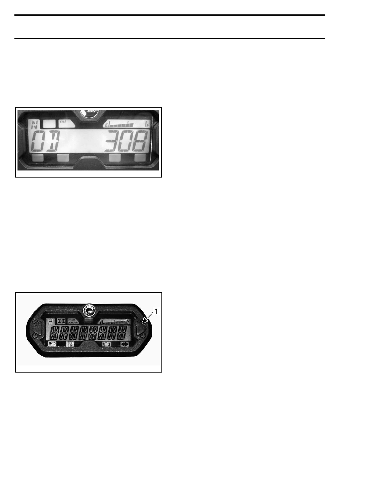
3. Press and release selector button once to display OD (odometer).
4. Press the selector button again, this time for 2
seconds.
This will change the Mode to either Speed, RPM
or Combined.
vdd2008-001-083
5. To select another mode, repeat steps 3 and 4
until the desired mode is displayed.
Temporary Display Mode
In the temporary display mode, the following functions are available:
– Odometer
–Clock
– Trip meter (resettable)
– Trip Hour meter (resettable)
– Engine hour meter.
Press and release selector button to change the
default display mode to the temporary mode.
7-050-002_c
vmr200
1. Selector button
TROUBLESHOOTING
DIAGNOSTIC TIPS
NOTE: It is a good practice to check for fault
codes using B.U.D.S. software as a first troubleshooting step. Refer to
TOOLS AND B.U.D.S.
IMPORTANT: Wh
system fault,
connections
check battery condition, cables and
first.
subsection.
en troubleshooting an electrical
Testing the Circuit
Check the rel
fuse tester o
lead to a wron
NOTE: If the ignition switch is left ON for more
than 50 minutes, the accessory relay will shut
down.
Inspecting
When replacing an electric or electronic component, always check electrical connections. Make
sure they are tight, make good contact, and are
corrosion-free. Dirty, loose or corroded contacts
are poor conductors and are often the source of a
system or component malfunction.
Pay particular attention to ensure that pins are not
bent or pushed out of their connectors.
Ensure all
wires, and
tened.
Check for signs of moisture, corrosion or dullness.
Clean pins properly and coat them with
TRIC GREASE (P/N 293 550 004)
lubricant when reassembling t hem, except if otherwise specified such as for the ECM connector.
Pay attention to ground wires.
For wirin
WIRING HA
tion.
ated-circuit fuse condition with a
r test lamp (a visual inspection could
g conclusion).
the Electrical Connection
wire terminals are properly crimped on
connector housings are properly fas-
g harness connector locations, refer to
RNESS AND CONNECTORS
COMMUNICATION
DIELEC-
or other appropriate
subsec-
The gauge will display the selected mode for 10
seconds then will return to the normal display
mode.
While in a resettable mode, push and HOLD selector button for 2 seconds to reset it.
4 vmr2016-410
Page 5

Subsection 07 (LIGHTS, GAUGE AND ACCESSORIES)
DIAGNOSTIC GUIDELINES
(GAUGE)
MULTIFUNCTION GAUGE WILL NOT
COME ON
1. M ultifunction gauge not powered up.
- Check fuse (F4), refer to POWER D ISTRIBUTION
subsection.
- Test diode D11, refer to WIRING D IAGRAM.
- Test multifunction gauge 12 Vdc input and ground
circuits as per MULTIFUNCTION GAUGE WIRE
IDENTIFICATION in this subsection. Refer to
WIRING DIAGRAM.
2. Defective Multifunction Gauge.
- Replace multifunction gauge.
RELAYS/SPEEDO FUSE (F4) BURNS OUT
REPEATEDLY
1. Taillight/Brake light system short circuit.
- Check taillight/brake light bulbs and circuit
MULTIFUNCTION GAUGE
COMMUNICATION ERROR
1. M ultifunction gauge CAN circuit open.
- Ensure multifunction gauge is properly connected
and powered up.
- Check for applicable fault code using B.U.D.S., refer to DIAGNOSTIC AND FAULT CODES subsection.
- Carry out a MULTIFUNCTION GAUG E CAN RESISTOR TEST in this subsection.
- Carry out a continuity test of the multifunction
gauge CAN wires, refer to WIRING DIAGRAM.
NO FUEL QUANTITY INDICATION
1. Defective fuel level sender or wiring.
- Refer to FUEL TANK AND FUE L PUMP subsection.
2. Defective Multifunction Gauge.
- Replace multifunction gauge, refer to MULTIFUNCTION GAUGE in this subsection.
DIAGNOSTIC GUIDELINES
(LIGHTS)
LOW AND HIGH BEAM HEADLIGHTS WILL
NOT COME ON SIMULTANEOUSLY
1. Jumper JP1 is open circuit or missing.
- Check jumper (fuse) JP1 in front fuse box, refer
to POWER DISTRIBUTION subsection.
BRAKE LIGHTS WILL NOT COME ON
WHEN BRAKES APPLIED
1. Defective brake relay.
- Test brake relay (R8), refer to POWER DISTRIBUTION subsection.
2. Defective brake light switch(es).
- Refer to BRA KE LIGHT SWITCHES in the BRAKE
subsection.
3. Defective wiring/connectors.
- Test wiring continuity, refer to applicab le WIRING
DIAGRAM.
TURN SIGNAL LIGHTS WILL NOT COME
ON WHEN SELECTED (CE MODELS)
1. Accessories fuse (F7) open circuit (turn signals
inoperative only).
- Test fuse, refer to POWER DISTRIBUTION sub-
section.
2. Clock/Hazard fuse (F10) open circuit (turn signals and hazard lights inoperative).
- Test fuse, refer to POWER DISTRIBUTION sub-
section.
3. Defective Flasher Module.
- Replace flasher mod ule, refer to FLASHER MOD-
ULE in this subsection.
4. Defective wiring/connectors.
- Test wiring continuity, refer to applicab le WIRING
DIAGRAM.
HAZARD LIGHTS WILL NOT COME ON
WHEN SELECTED (CE MODELS ONLY)
1. Clock/Hazard fuse (F10) open circuit.
- Check fuse, refer to POWER DISTRIBUTION sub-
section.
2. Hazard lights 12 Vdc input circuit open.
- Check wiring and connectors as per TURN SIG-
NAL/HAZARD LIGHTS WIRE IDENTIFICATION in
this subsection. Refer to WIRING DIAGRAM.
3. Hazard lights selector switch defective.
- Test switch as per TURN SIGNAL/HAZARD
LIGHTS WIRE IDENTIFICATION in this s ubsection. Refer to WIRING DIAGRAM.
4. Defective wiring/connector between hazard
lights selector switch and flasher module.
- Refer to WIRING DIAGRAM.
5. Flasher module ground circuit open.
- Test wiring and connectors, refer to WIRING DI-
AGRAM.
vmr2016-410 5
Page 6
Subsection 07 (LIGHTS, GAUGE AND ACCESSORIES)
6. Defective flasher module.
- Replace flasher module, refer to FLASHER MODULE in this subsection.
HAZARD LIGHTS COME ON WITHOUT
BEING SELECTED (CE MODELS ONLY)
1. Hazard lights switch or wiring short circuit.
- Check for water in LH multifunction switch.
- Test hazard light switch and wiring, refer to
WIRING DIAGRAM.
2. Resistor R1 in flasher module input circuit is
open.
-TestresistorR1,refertoWIRINGDIAGRAM.
TURN SIGNAL/HAZARD LIGHTS
INDICATOR IN MULTIFUNCTION GAUGE
WILLNOTCOMEONWITHTURNSIGNAL
OR HAZARD LIGHTS SELECTED ON,
IGNITION SWITCH ON (CE MODELS
ONLY)
1. Signal wire from flasher module to multifunction gauge open circuit.
- Test circuit continuity from flasher m odule
(3–MC2–4) to multifunction gauge (1–C1–8).
2. Defective flasher module.
- Replace flasher module, refer to FLASHER MOD-
ULE in this subsection.
3. Defective multifunction gauge.
- Replace multifunction gauge.
HORN WILL NOT FUNCTION (CE MODELS
ONLY)
1. Burnt Clock/Hazard fuse (F10)
-Checkfuse
2. Defective horn.
-Testhornbyapplying12Vdcandgroundjumper
to ho rn.
3. Defective horn switch.
- Test horn switch as per HORN WIRE IDENTIFICATION in this subsection. Refer to WIRING DIAGRAM.
4. Defective wiring.
- Check wiring continuity as per HORN WIRE
IDENTIFICATION in this subsection. Refer to
WIRING DIAGRAM.
PROCEDURES
MULTIFUNCTION GAUGE
Reseting the Maintenance Required
Message
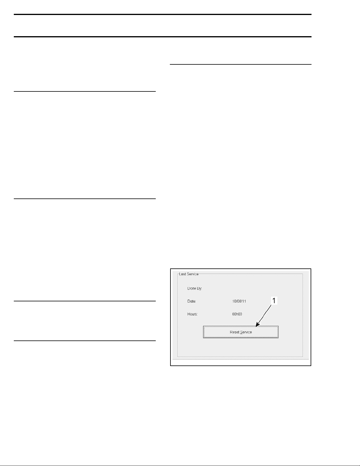
Connect to the latest applicable B.U.D.S. software
version. Refer to
AND B.U.D.S.
subsection.
Select Vehicle tab.
Click on the Reset Service button.
COMMUNICATION TOOLS
HAZARD LIGHTS INDICATOR NOT
WORKING WITH IGNITION SWITCH OFF
(CE MODELS ONLY)
1. Diode D10 open circuit.
- Test diode, refer to WIRING DIAGRAM.
POSITION LIGHTS WILL NOT COME ON
(CE MODELS ONLY)
1. Accessories fuse open circuit.
- Test fuse F12, refer to POWER DISTRIBUTION
subsection.
2. Power or ground circuit wiring.
- Check wiring continuity, refer to WIRING DIAGRAM.
3. Defective light bulbs
- Test/replace light bulbs.
tmr2011-030-014_a
TYPICAL
1. Reset S
ervice button
6
vmr2016-410
Page 7
Subsection 07 (LIGHTS, GAUGE AND ACCESSORIES)
Multifunction Gauge Wire
Identification
FUNCTION PIN COLOR
12 volt input from fuse F4
12 volt input from
fuse F10 (Clo
Ground
CAN LO
CAN HI
Fuel level gauge supply
Fuel level gauge ground 21
2WD/4WD swit
signal (-)
HI beam signa
Vehicle speed sensor
signal (VSS
ck)
ch
l(+)
)
17
ORANGE/YELLO
16 RED/WHITE
20
18
19
4
7
5
9PINK
BLACK
WHITE/BLACK
WHITE/BEIGE
BROWN/PINK
VIOLET/PINK
BLACK/BEIGE
BLUE
W
Multifunction Gauge Circuit Protection
CONDITION CIRCUIT PROTECTION
Fuse 10 of fuse block 1
Supplied a
talltimes
(fromfuse1offuse
block 2)
4. If the 12-hour format was selected, choose Am
(A) or Pm (P) by pressing button.
5. Choose hour first digit by pressing button.
6. Choose hour second digit by pressing button.
7. Choose minutes first digit by pressing button.
8. Choose minutes second digit by pressing button.
9. Press button to enter settings (CLOCK will appear on display).
NOTE: The gauge will display the current time for
10 seconds then will return to the normal display
mode.
Setting the Multifunction Gauge w ith
B.U.D.S.
Connect to the applicable B.U.D.S. software. Refer to
subsection.
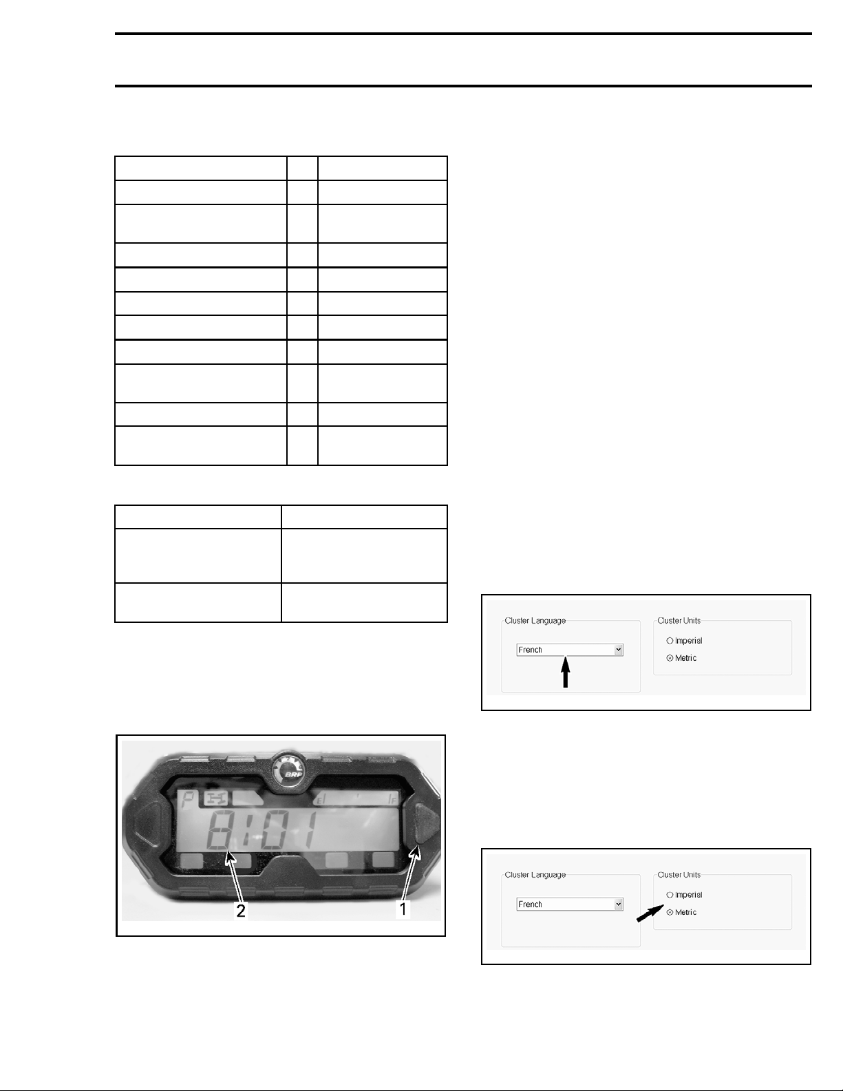
Language Selection
In B.U.D.S., select the:
– Setting page tab
– Cluster page tab.
Scroll and select the desired display language in
the Cluster Language box.
COMMUNICATION TOOLS AND B.U.D.S.
Supplied with main relay
activated
Fuse 4 of f
(from main relay R2)
use block 1
Setting the Clock with Gauge Selector
Button
To set current time, proceed as follows:
1. Select the clock display.
vmo2011-008-001_a
1. Selec
2. Time
2. Press and HOLD selector button.
NOTE: The display will flash.
3. Choo
tor button
se the 12-hour (12H) or 24-hour (24H) for-
y pressing button.
mat b
vmr2016-137-001_a
Units of Display Selection
In B.U.D.S., select the:
– Setting page tab
– Cluster page tab.
Select Imperial or Metric in the Cluster Units
box.
vmr2016-137-001_b
vmr2016-410 7
Page 8
Subsection 07 (LIGHTS, GAUGE AND ACCESSORIES)
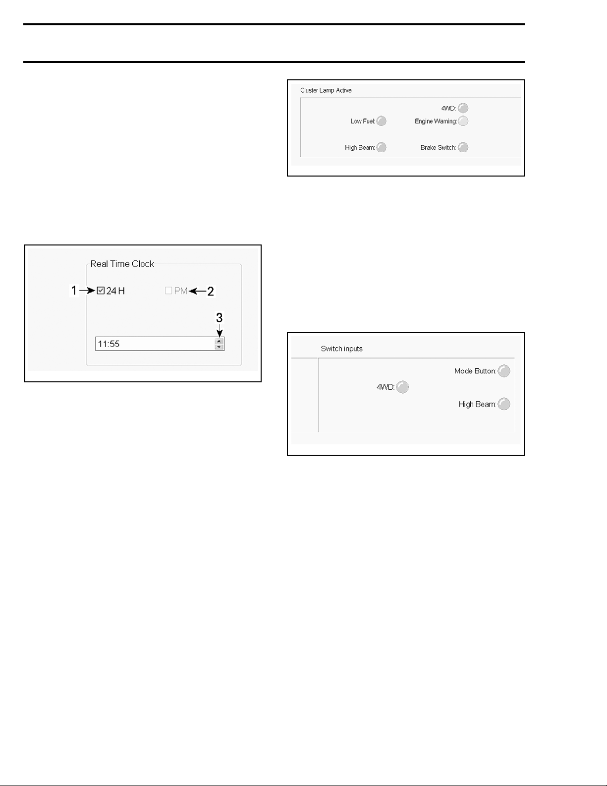
Clock Setting
In B.U.D.S., select the:
– Setting page tab
– Cluster page tab.
To set clock to the 24-hour format, check the 24 H
box. To set it to the 12-hour format, leave the box
empty.
If 12-hour format was selected, check the PM box
if required.
Set hour and minutes using the up or down arrows.
vmr2016-137-003
TYPICAL - CLUSTER LAMP A CT IVE BOX
This function confirms that the signals are broadcasting and the indicator lights should be ON in
the m ultifunction gauge.
Switch Input Monitoring
In B.U.D.S.,
– Monitoring page
– Cluster tab.
Use the Switch Inputs box to monitor different
switch inputs as you activates the switches.
select the:
37-002_a
vmr2016-1
TYPICAL
1. 24 H box
2. PM box
3. Arrows
Testing the Multifunction G augewith
B.U.D.S.
Connect to
version.
AND B.U.D
Wow Test
This function is used to check if the indicator
lights, display and analog indicators (if applicable)
are functional.
NOTE: Thi
external
In B.U.D.S., select the:
– Activati
– Cluster tab.
Click on t
Indicator Lights Monitoring
In B.U.D.S., select the:
– Monitoring page
– Cluster
Use the Cluster Lamp Active box to monitor different indicator lights outputs.
the latest applicable B.U.D.S. software
Refer to
.S.
COMMUNICATION TOOLS
subsection.
s function does not test the signals or
circuits.
on page
he WOW Test button.
tab.
vmr2016-137-004
TYPICAL -
SWITCH INPUTS BOX
This function confirms that the multifunction
gauge receives the inputs.
Vehicle P
arameters Monitoring
In B.U.D.S., select the:
– Monitori
ng page
– Cluster tab.
In the up
followi
per area of the B .U.D.S. cluster page, the
ng indications are displayed.
– Engine speed (RPM)
– Vehicle speed
– Fuel lev
el.
These indications confirm that the applicable signals are transmitted and the information should be
displayed in the multifunction gauge.
Tes ti n
g the Multifunction Gauge CAN
Resistor
1. On so equipped models, disconnect DPS1 connector (control) from the DPS module, refer to
STEERING SYSTEM
subsection.
8 vmr2016-410
Page 9
Subsection 07 (LIGHTS, GAUGE AND ACCESSORIES)
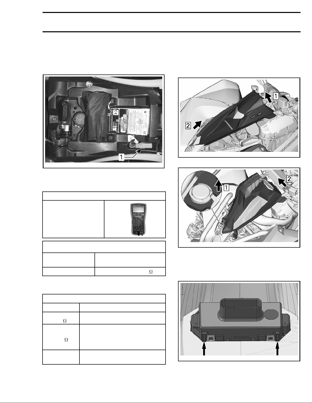
2. Remove seat to access diagnostic link connector (DB).
3. Remove diagnostic link connector from its
holder.
vmr2012-023-003_a
1. Diagnostic link connector (DB)
4. Measure t
he resistance of the CAN resistors as
follows.
Removing the M ultifunction Gauge
1. Remove console panel, refer to
tion.
2. Pull gauge support from vehicle.
vmr2016-410-004_a
EXCEPT X MR MODEL
BODY
subsec-
REQUIRED TOOL
FLUKE 115
MULTIMETER
(P/N 529 035 868)
CAN RESISTOR TEST
DIAGNOSTIC LINK
CONNECTOR
RESISTANCE
Pins 1 and 2 Approximately 60
NOTE: This tests both the ECM and the Cluster
CAN resistors and wires.
TEST RESULT
READING POSSIBLE CAUSE
Approximately
60
Approximately
120
ECM and CLUSTER CAN wires and
resistors good
CAN wire to CLUSTER open
CAN w
iretoECMopen
CLUSTER CAN resistor open
ECM CAN resistor open
vmr2016-410-005_a
XMRMODEL
3. From th
the gau
from it
s support.
e back of the gauge support, release
ge retaining tabs and remove the gauge
Infinite
(open circuit)
vmr2016-410 9
CAN wire to DB connector open
circuit
vmr2012-035-003_a
GE REL EASE TABS (4)
GAU
Page 10
Subsection 07 (LIGHTS, GAUGE AND ACCESSORIES)
Installing the Multifunction Gauge
For the installation, reverse the removal procedure.
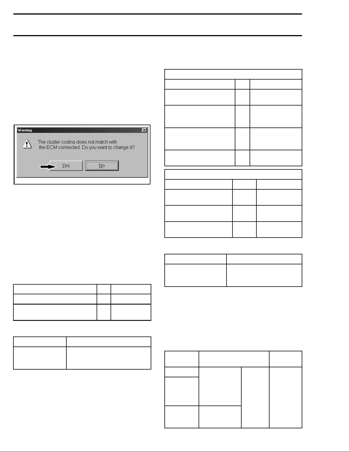
New Multifunction Gauge Registration
(coding)
Whenever the multifunction gauge is replaced,
B.U.D.S. must be used to register it in the ECM.
Simply click Yes when the following message
appears.
vmr2006-020-058_a
12 VOLT POWER OUTLET
Removing and installing the 12 Volt
Power Outlet
DY
Refer to
BO
ner fender
Unplug the connectors of the power outlet.
Unscrew the retaining nut.
Reverse pr
subsection and remove the RH in-
panel.
ocedure for installation.
HEADLIGHTS
Headlight Wire I dentification
HEADLIGHTS RELAY (R5)
FUNCTION PIN COLOR
12 volt input from fuse
F11 (headlights power)
12 volt input from
ignition switch pin A
(relay winding input)
12 volt output to
headlights low beam and
low/high beam switch
Relay winding ground
(from ECM K2)
HEADLIGHT LOW/HIGH BEAM SWITCH
FUNCTION PIN COLOR
12 volt input from
headlights relay
12 volt output to high
beam headlights
12 volt output to low
beam headlights
Headlights Circuit Protection
CONDITION CIRCUIT PROTECTION
C6 YELLOW/BLACK
D6
D7 RED/BLUE
C7 ORANGE/BLACK
MG2-4 RED/YELLOW
MG2-5
MG2-2 GREEN
YELLOW/BLUE
BLUE
12 Volt Power Outlet Wire
Identific
12 volt inp
Ground
(togroundterminalBK3)
ation
FUNCTION PIN COLOR
ut from fuse F12
2
RED/BROWN
1
BLACK
12 Volt Power Outlet Circuit Protection
CONDITIO
Supplied w ith
accessor
activated
ies relay
N
CIRCUIT P
(from accessories relay R3)
ROTECTION
Fuse 12
Supplied when
headlights relay (R5)
activated
Fuse 11
Testing the Headlight
1. Disconnect LOW beam and HIGH beam headlight connectors. Refer to
MENT
.
2. Set ignition switch to ON (with lights).
3. Measure the voltage on headlight connector as
follows.
SWITCH
POSITION
LO beam
HI beam
(only on
vehicle
with DPS)
HI beam
WIRE COLOR VOLTAGE
GREEN
(Low beam
connector)
BLUE
(Hi beam
connector)
BULB REPLACE-
BLACK
Battery
voltage
10 vmr2016-410
Page 11
Subsection 07 (LIGHTS, GAUGE AND ACCESSORIES)
4. Remove the JP1 jumper/fuse, refer to
DISTRIBUTION
subsection.
POWER
5. Measure the voltage on headlight connector as
follows.
SWITCH
POSITION
LO beam
HI beam
LO beam
HI beam
WIRE COLOR VOLTAGE
GREEN
(Low beam
connector)
BLACK
BLUE
(Hi beam
connector)
No voltage
No voltage
Battery
voltage
Battery
voltage
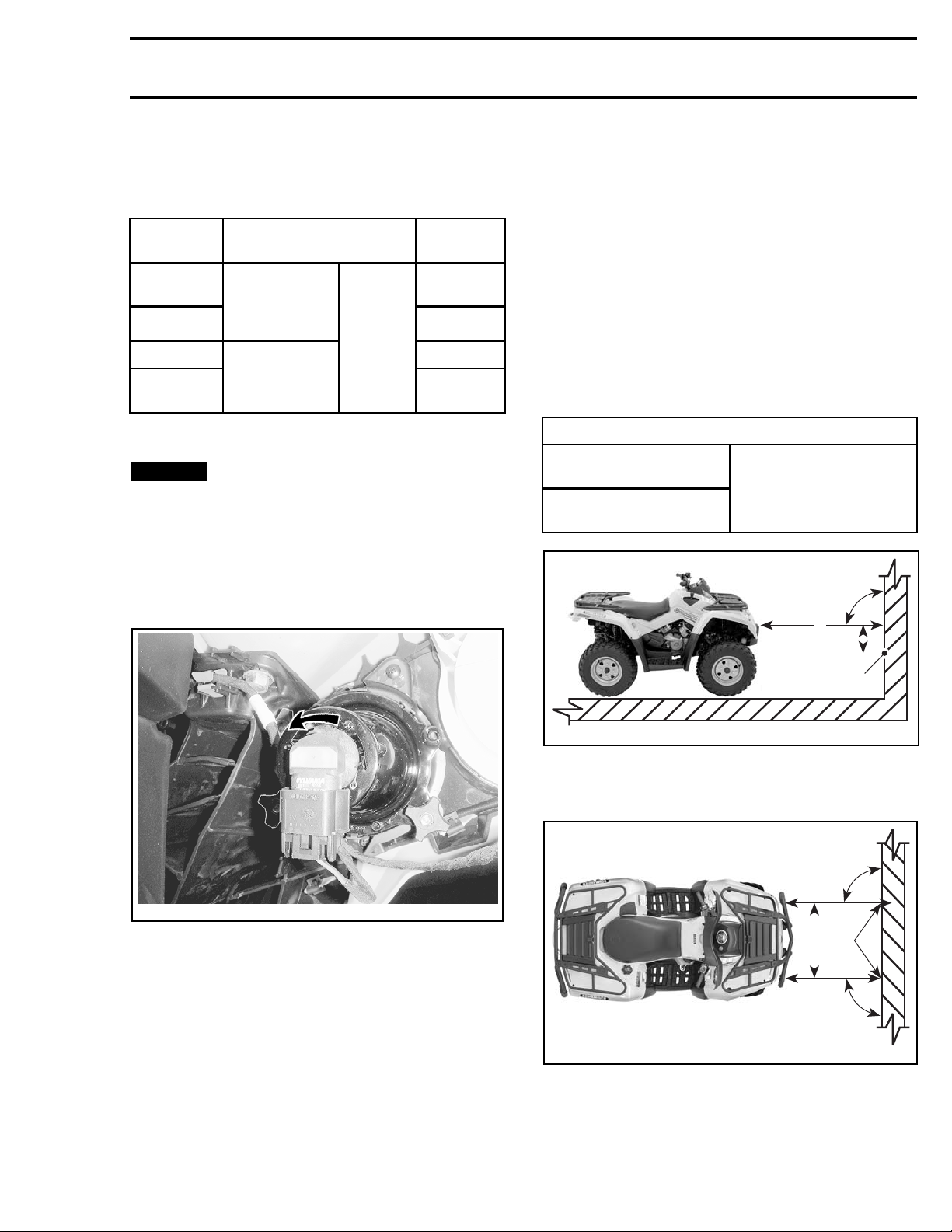
Replacing the Headlight Bulb
NOTICE
gen bulb with bare fingers, it shortens its operating life. If glass is touched, clean it with isopropyl alcohol which will not leave a film on
the bulb.
1. Unplug co
2. Rotate bulb.
Never touch glass portion of a halo-
nnector from bulb.
2. Measure the distance from the center of each
headlight to the ground (high beam and low
beam).
3. Trace a line on the test surface parallel to the
ground at each measured height (one for high
beam and one for low beam).
Low beam aiming is correct when the crest of the
low beam is below the applicable horizontal center line traced on the test surface as per specification.
High beam aiming is correct when the center of
the high beam (focus point) is below the applicable horizontal center line traced on the test surface as per specification.
SPECIFICATION
Low beam crest (top
of low beam)
High beam center
(focus point)
25 mm to 125 mm
(1 in to 5 in
applicable line
) below
90°
A
B
vmo2012-012-060_b
TYPICAL
3. Pull bulb out.
4. Properly reinstall removed parts in the reverse
order of their removal.
5. Validate headlight operation.
Adjusting the Headlamp Beam
NOTE: Load v ehicle as per normal u se.
1. Position vehicle on a level surface 5 m (16 ft) in
front of a test surface ( wall or screen) as in first
illustration.
1
vmr2006-020-002_a
TYPICAL
1. Light be
A. 5m (16ft)
B. Beam aiming specification
am center
90°
2
1
90°
006-020-001_a
vmr2
TYPICAL
1. Headlight center lines
t beam center
2. Ligh
Beam Aiming Adjustment
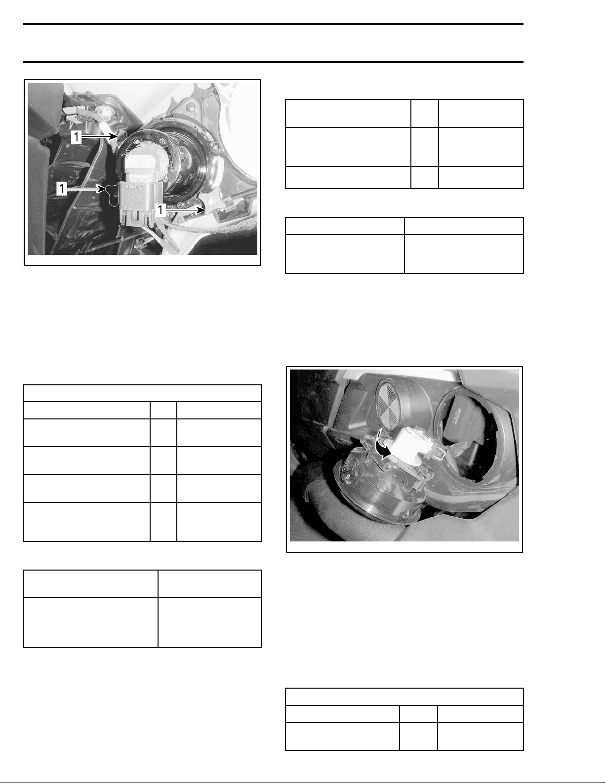
Turn adjustment knobs to adjust beam height and
side orientation to specification.
vmr2016-410 11
Page 12
Subsection 07 (LIGHTS, GAUGE AND ACCESSORIES)
Taillight Wire Identification
vmo2012-012-060_a
LOW AND HIGH BEAMS
1. Adjustment knobs
TAILLIGHTS/BRAKE LIGHTS
Brake Light Switch
For brake light switch location and testing, refer to
BRAKES
Brake Light Wire Identification
subsection.
BRAKE LIGHT RELAY (R8)
FUNCTION PIN
Supplied when
Accessories r
activated
Ground from BK2
elay R3
3
2
CIRCUIT
PROTECTION
RED/VIOLET
BLACK
Taillight Circuit Protection
CONDITION CIRCUIT PROTECTION
Supplied when
Accessories relay R3
activated
Fuse 14 (fro
Accessories relay R3)
m
Replacing the Taillight/Brake Light
Bulb
1. Unplug connector from bulb.
2. Rotate light bulb counterclockwise to remove it
from taillight.
FUNCTION PIN COLOR
12 volt input from fuse
F14 (brake light power)
12 volt input from F4 (relay
winding inpu t)
12 volt output to LH and
RH brake lights
Relay winding ground
(from brake light
switch(es))
C8 RED/VIOLET
D8
ORANGE/GREEN
D9
WHITE/ORANGE
C9 RED/ORANGE
Brake Light Circuit Protection
CONDITION
Supplied when:
sories relay
Acces
R3 activated
Brake relay R8 activa ted
CIRCUIT
PROTEC
Fuse 1 4 (from
Accessories relay R3)
TION
vmo2012-012-062_a
ROTATE BULB COUNTERCLOCKWISE
3. Remov
e bulb socket from taillight.
Installation is the reverse of the removal procedure.
TURN SIGNALS/HAZARD
(CE MODELS ONLY)
Tur n S
Identification
ignal/Hazard Lights Wire
FLASHER MODULE
FUNCTION PIN COLOR
12 volt input from
fuse F10
12 vmr2016-410
MC2-1
RED/
WHITE
Page 13
Subsection 07 (LIGHTS, GAUGE AND ACCESSORIES)
FLASHER MODULE
FUNCTION PIN COLOR
12 volt input from
fuse F7
RH turn 12 volt input
from turn signal switch
LH turn 12 volt input
from turn signal switch
Output to RH turn
signal lights
Output to LH turn signal
lights
Output to multifunction
gauge (turn signal
indicator)
Ground MC1-4 BLACK
Hazard 12 volt input
from hazard switch
TURN SIGNAL SWITCH
(IN MULTIFUNCTION SWITCH)
MC1-5 RED/BLACK
MC1-1 BEIGE/BROWN
MC1-2 BEIGE/GRAY
MC2-2 BROWN
MC2-3 GRAY
MC2-4 ORANGE
MC1-6 BEIGE/RED
HAZARD CIRCUIT
CONDITION CIRCUIT PROTECTION
Battery power
(continuous)
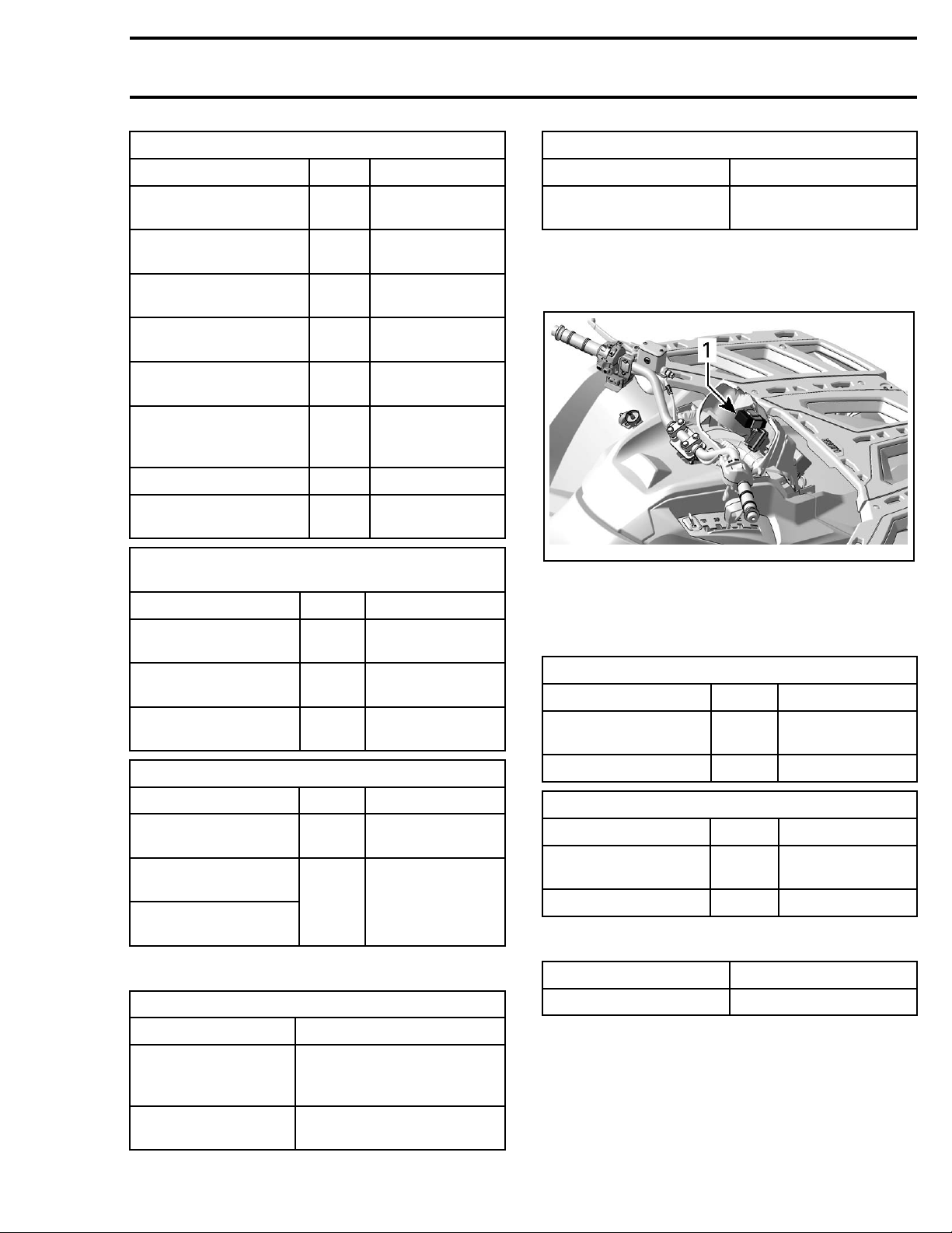
Flasher Module Access
Remove multifunction gauge.
vmr2012-035-012_a
1. Flasher module location
Fuse 10
FUNCTION PIN COLOR
12 volt input from
fuse F10
RH turn 12 volt output
to flasher module
LH turn 12 volt output
to flasher module
HAZARD S
FUNCTION PIN COLOR
12 volt input from
fuse F10
12 volt output to
flasher module
12 volt output to
wake up gauge
MG3-3 RED/BLACK
MG3-1 BEIGE/BROW N
MG3-2 BEIGE/GRAY
WITCH
MG3-3 RED/BL
MG3-5 BEIGE
ACK
/RED
Turn Signal/Hazard Circuit Protection
TURN SIGNAL CIR CUIT
CONDITION CIRCUIT PROTECTION
HORN (CE MODELS O NLY)
Horn Wire
HORN SWITCH (IN MULTIFUNCTION SWITCH)
FUNCTIO
12 volt input from
fuse F10
12 volt output to horn
FUNCTI
12 volt input from
horn sw
Ground
Horn Circuit Protection
CONDITION CIRCUIT PROTECTION
Battery power Fuse 10
Identification
N
ON
itch
PIN COLOR
MG3-3 RED/BLACK
MG3-4 BEIGE/BLACK
HORN
PIN COLOR
2
1
BEIGE/BLACK
BLACK
Supplied with
Accessories relay
(R3) activated
Battery power
(continuous)
vmr2016-410 13
Fuse 7 (from Accessories
yR3)
rela
Fuse 10
Page 14
Subsection 07 (LIGHTS, GAUGE AND ACCESSORIES)
WINCH
Winch Wire Identification
WINCH RELAY
FUNCTION PIN COLOR
12 volt input from battery
(winch power)
Ground SW4 BLACK
12 volt input from
switch (IN)
12 volt input from
switch (OUT)
Motor power (switches
polarity depending on
rotation direction)
Motor power (switches
polarity depending on
rotation direction)
RD RED
SW1 GREEN/BLUE
SW2 LIGHT B LUE
SW3
SW5
RED (with blue
sleeve)
RED (with
yellow sleeve)
NOTE: The small black wire at terminal BN4 connected to the diodes are used to prevent electric
arcs in the switch.
WINCH SWITCH
FUNCTION PIN COLOR
12 volt input from fuse 7 A
12 volt output to relay
winding (IN)
12 volt output to relay
winding (OUT)
CGREEN/BLUE
B
RED/BLACK
LIGHT BLUE
WARNING
Before testing, make sure the winch is in
FREESPOOL mode (Freespool clutch disengaged).
tmr2011-030-003_a
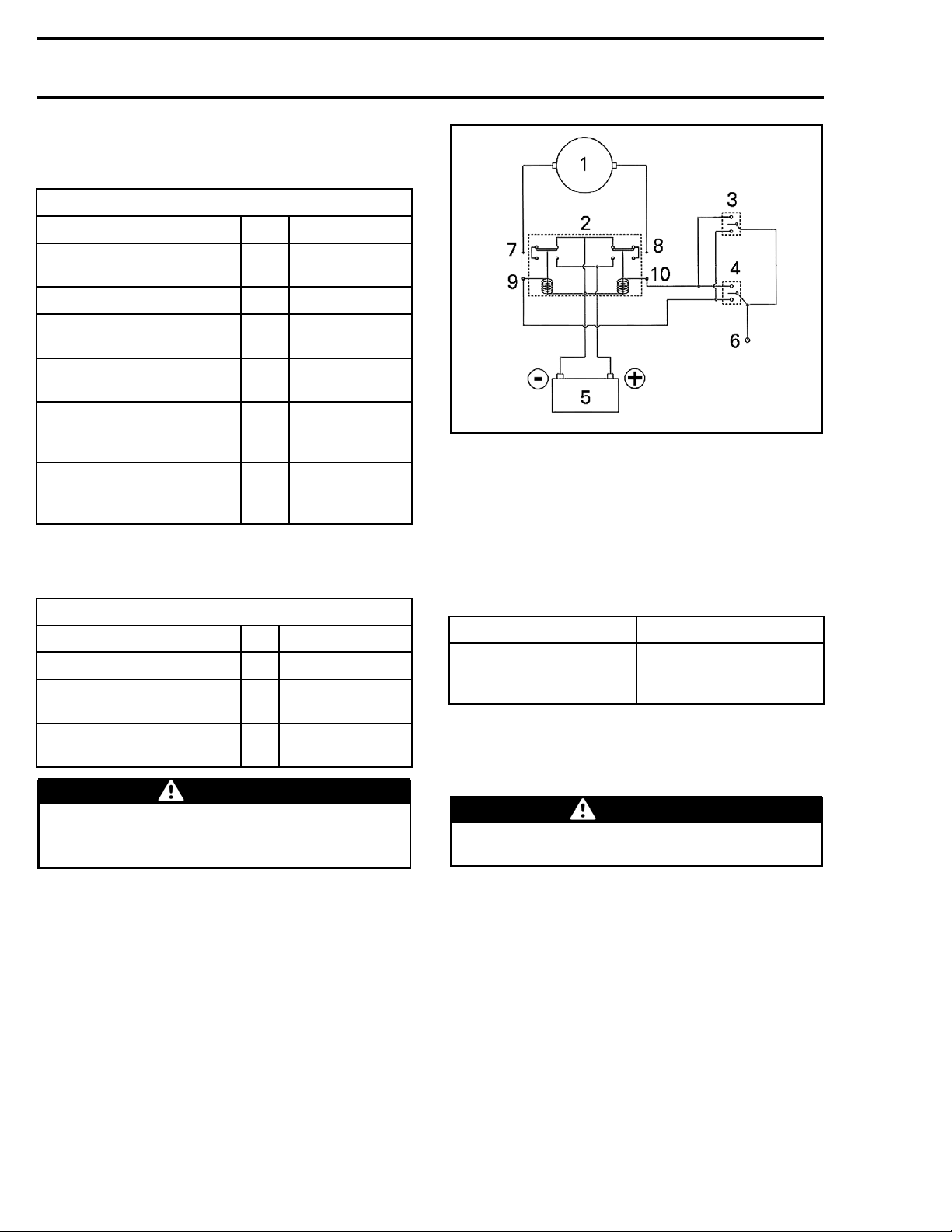
SIMPLIFIED WINCH WIRING DIAGRAM
1. Winch motor
2. Winch relay
3. Winch remote control
4. Winch switch
5. Battery
6. 12 volt input to switch (switch pin 2 - from fuse 7)
7. Winch motor power (SW3)
8. Winch motor power (SW5)
9. 12 volt input to relay winding (IN - SW1)
10.12 volt input to relay winding (OUT - SW2)
Winch Switch Circuit Protection
CONDITION CIRCUIT PROTECTION
Supplied
accessories relay
activated
when
Fuse 7 (from accessories
relay R3)
Removing the Winch
1. Disconn
then th
ect, the battery BLACK (-) cable first,
eRED(+)cable.
WARNING
Always respect this order for disassembly;
disconnect BLACK (-) cable first.
2. Remove the hook.
2.1 Remove and discard the cotter pin.
2.2 Remove the hook pin.
14 vmr2016-410
Page 15
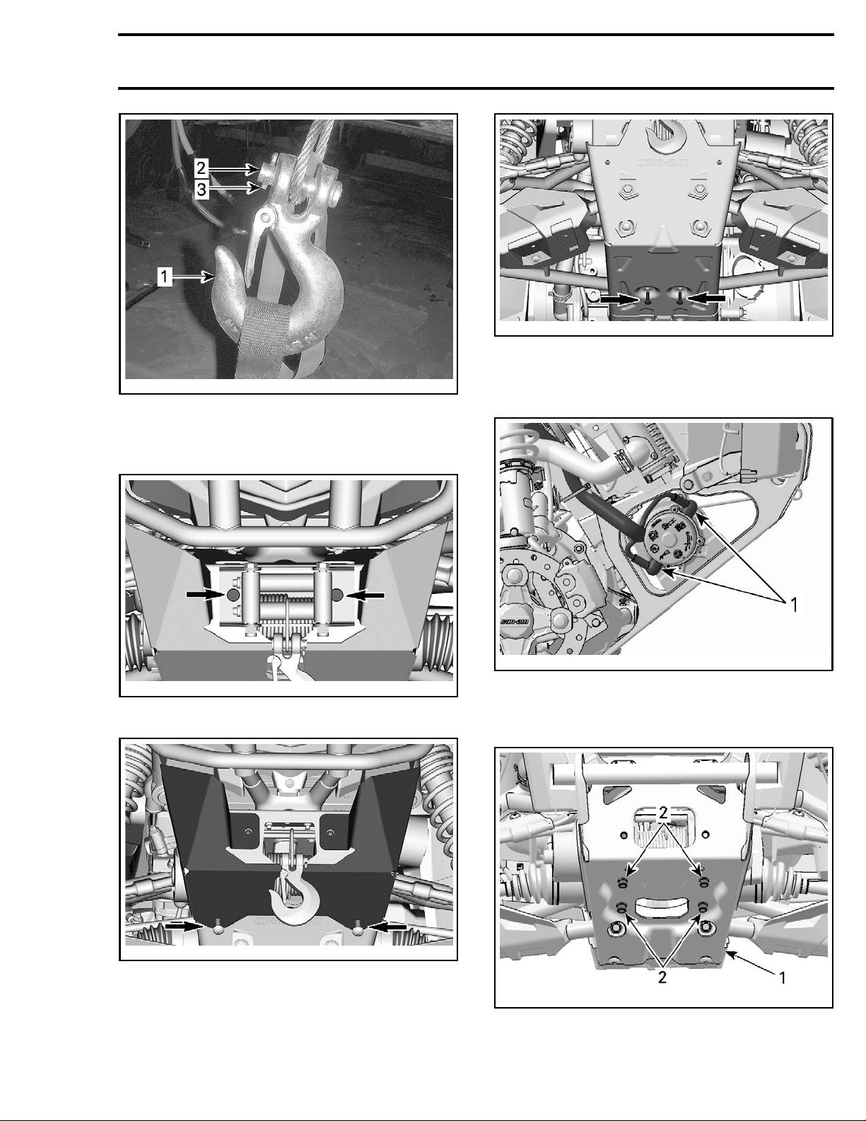
tsi2011-004-009_a
1. Hook
2. Hook pin
3. Cotter p in
3. Remove the winch cable fairlead.
Subsection 07 (LIGHTS, GAUGE AND ACCESSORIES)
vmr2016-410-003_a
6. Disconnect both winch power cables.
NOTE: Note the position of the power cables for
reinstallation.
vmr2016-410-001_a
4. Remove the Front lower fascia.
vmr2016-410-002_a
5. Remove the front skid plate.
-035-010_a
vmr2012
1. Winch power cables
7. Remove the four winch retaining screws from
the front bumper support.
vmr2012-035-011_a
1. Front bumper support
2. Winch retaining screws
8. Remove winch.
vmr2016-410 15
Page 16
Subsection 07 (LIGHTS, GAUGE AND ACCESSORIES)
Installing the Winch
For the installation, reverse the removal procedure, however pay attention to the following.
Connect winch power cables as noted at removal.
NOTE: If the winch power cables are not con-
nected correctly, the winch motor will operate in
the reverse direction of selection.
TIGHTENING TORQUE
Winch retain
Winch power c
Winch fairlead elastic
Install a NE
ing screws
nuts
W cotter pin on the hook pin.
ables
16 N•m ± 2 N•m
(142 lbf•in ±18lbf•in)
7N•m ± .5N•m
(62 lbf•in ±4lbf•in)
4.5N•m ± .5N•m
(40 lbf•in ±4lbf•in)
16 vmr2016-410
 Loading...