

Page 1
INSTALLATION / OPERATION
USER’S MANUAL
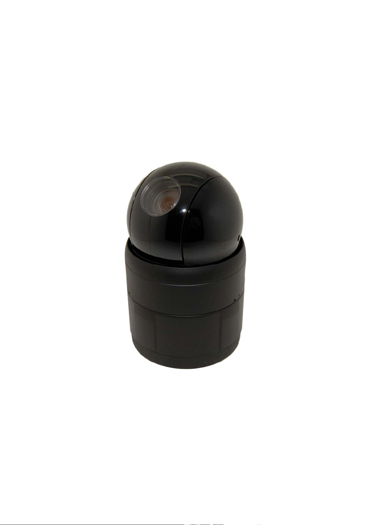
IPSD202MT
X20 Full HD Megapixel Speed
Dome Network Camera
1
Page 2
WARNING
TO REDUCE THE RISK OF FIRE OR ELECTRIC SHOCK, DO NOT EXPOSE THIS PRODUCT TO RAIN OR
MOISTURE. DO NOT INSERT ANY METALLIC OBJECTS THROUGH THE VENTILATION GRILLS OR
OTHER OPENINGS ON THE EQUIPMENT.
CAUTION
CAUTION: TO REDUCE THE RISK OF ELECTRIC SHOCK,
DO NOT REMOVE COVER (OR BACK).
NO USER-SERVICEABLE PARTS INSIDE.
REFER SERVICING TO QUALIFIED SERVICE PERSONNEL.
CAUTION
RISK OF ELECT RNIC SHOCK
DO NOT OPEN
EXPLANATION OF GRAPHICAL SYMBOLS
The lightning flash with arrowhead symbol, within an equilateral triangle, is intended to alert
the user to the presence of uninsulated "dangerous voltage" within the product's enclosure
that may be of sufficient magnitude to constitute a risk of electric shock to persons.
he exclamation point within an equilateral triangle is intended to alert the user to the
T
presence of important operating and maintenance (servicing) instructions in the literature
accompanying the product.
PRECAUTIONS
Safety ---------------------------------- Installation -----------------------------
Should any liquid or solid object fall into the cabinet,
unplug the unit and have it checked by the qualified
personnel before operating it any further.
Unplug the unit from the wall outlet if it is not going to
be used for several days or more. To disconnect the
cord, pull it out by the plug. Never pull the cord itself.
Allow adequate air circulation to prevent internal heat
build-up. Do not place the unit on surfaces (rugs,
blankets, etc.) or near materials(curtains, draperies)
that may block the ventilation holes.
Height and vertical linearity controls located at the rear
panel are for special adjustments by qualified
personnel only.
Do not install the unit in an extremely hot or humid place
or in a place subject to excessive dust, mechanical
vibration.
Cleaning ----------------------------------
Clean the unit with a slightly damp soft cloth.
Use a mild household detergent. Never use strong
solvents such as thinner or benzene as they might
damage the finish of the unit.
Retain the original carton and packing materials for safe
transport of this unit in the future.
2
Page 3

FCC COMPLIANCE STATEMENT
FCC INFORMATION: THIS EQUIPMENT HAS BEEN TESTED AND FOUND TO
COMPLY WITH THE LIMITS FOR A CLASS A DIGITAL DEVICE, PURSUANT TO PART 15 OF THE FCC
RULES. THESE LIMITS ARE DESIGNED TO PROVIDE REASONABLE PROTECTION AGAINST
HARMFUL INTERFERENCE WHEN THE EQUIPMENT IS OPERATED IN A COMMERCIAL
ENVIRONMENT. THIS EQUIPMENT GENERATES, USES, AND CAN RADIATE RADIO FREQUENCY
ENERGY AND IF NOT INSTALLED AND USED IN ACCORDANCE WITH THE INSTRUCTION MANUAL,
MAY CAUSE HARMFUL INTERFERENCE TO RADIO COMMUNICATIONS. OPERATION OF THIS
EQUIPMENT IN A RESIDENTIAL AREA IS LIKELY TO CAUSE HARMFUL INTERFERENCE IN WHICH
CASE THE USER WILL BE REQUIRED TO CORRECT THE INTERFERENCE AT HIS OWN EXPENSE.
CAUTION: CHANGES OR MODIFICATIONS NOT EXPRESSLY APPROVED BY THE PARTY
RESPONSIBLE FOR COMPLIANCE COULD VOID THE USER'S AUTHORITY TO OPERATE THE
EQUIPMENT.
THIS CLASS A DIGITAL APPARATUS COMPLIES WITH CANADIAN ICES-003.
CET APPAREIL NUMÉRIQUE DE LA CLASSE A EST CONFORME À LA NORME NMB-003 DU
CANADA.
CE COMPLIANCE STATEMENT
WARNING
This is a Class A product. In a domestic environment this product may cause radio interference in
which case the user may be required to take adequate measures.
CAUTION
RISK OF EXPLOSION IF BATTERY IS REPLACED BY AN INCORRECT TYPE.
DISPOSE OF USED BATTERIES ACCORDING TO THE INSTRUCTIONS
3
Page 4

IMPORTANT SAFETY INSTRUCTIONS
1. Read these instructions.
2. Keep these instructions.
3. Heed all warnings.
4. Follow all instructions.
5. Do not use this apparatus near water.
6. Clean only with dry cloth.
7. Do not block any ventilation openings. Install in accordance with the
manufacturer’s instructions.
8. Do not install near any heat sources such as radiators, heat registers, stoves,
or other apparatus (including amplifiers) that produce heat.
9. Do not defeat the safety purpose of the polarized or grounding-type plug.
A polarized plug has two blades with one wider than the other. A grounding
type plug has two blades and a third grounding prong. The wide blade or the
third prong are provided for your safety. If the provided plug does not fit into
your outlet, consult an electrician for replacement of the obsolete outlet.
10. Protect the power cord from being walked on or pinched particularly at plugs
convenience receptacles, and the point where they exit from the apparatus.
11. Only use attachments/accessories specified by the manufacturer.
12. Use only with the cart, stand, tripod, bracket, or table
specified by the manufacturer, or sold with the apparatus.
When a cart is used, use caution when moving the
cart/apparatus combination to avoid injury from tip-over.
13. Unplug this apparatus during lightning storms or when
unused for long periods of time.
14. Refer all servicing to qualified service personnel. Servicing is
required when the apparatus has been damaged in any way, such as power-
supply cord or plug is damaged, liquid has been moisture, does not operate
normally, or has been dropped.
15. CAUTION – THESE SERVICING INSTRUCTIONS ARE FOR USE BY
QUALIFIED SERVICE PERSONNEL ONLY. TO REDUCE THE RISK
OF ELECTRIC SHOCK DO NOT PERFORM ANY SERVICING OTHER
THAN THAT CONTAINED IN THE OPERATING INSTRUCTIONS
UNLESS YOU QRE QUALIFIED TO DO SO.
16. Use satisfy clause 2.5 of IEC60950-1/UL60950-1 or Certified/Listed Class
2 power source only.
17. ITE is to be connected only to PoE networks without routing to the outside plant.
4
Page 5

TABLE OF CONTENTS
DESCRIPTION .............................................................................................................................................. 12
MODELS .......................................................................................................................................................... 12
KEY FEATURES ................................................................................................................................................ 12
COMPONENTS.................................................................................................................................................. 13
INSTALLATION ............................................................................................................................................ 14
BEFORE INSTALLATION.................................................................................................................................... 14
STARTING INSTALLATION ................................................................................................................................14
Base Installation ...................................................................................................................................... 14
Basic Configuration of Fastrax X20 Network Dome Camera System .............................................. 17
Setting Network Dome Camera Termination ...................................................................................... 18
Reset ......................................................................................................................................................... 18
Setting Network Dome Camera Address (ID) ..................................................................................... 20
Setting Network Dome Camera Protocol ............................................................................................. 20
Connections.............................................................................................................................................. 20
Setting Network Dome Camera Protocol ............................................................................................. 21
Micro SD Card Installation (Optional) .................................................................................................. 21
OPERATION................................................................................................................................................... 22
MINIMUM CONDITIONS FOR USING WEB BROWSER........................................................................................... 22
ACCESSING THE IP CAMERA............................................................................................................................. 22
MAIN MENU .................................................................................................................................................... 23
LIVE VIEW ..................................................................................................................................................... 24
LIVE VIDEO PAGE ICONS ................................................................................................................................. 24
PLAYBACK...................................................................................................................................................... 26
PLAYBACK VIEW .............................................................................................................................................. 26
SETUP.............................................................................................................................................................. 29
BASIC CONFIGURATION ................................................................................................................................... 29
Users ......................................................................................................................................................... 30
Network .................................................................................................................................................... 33
Image........................................................................................................................................................ 35
Audio ......................................................................................................................................................... 37
Date & Time............................................................................................................................................. 39
LIVE VIEW....................................................................................................................................................... 41
Source ....................................................................................................................................................... 41
VIDEO & IMAGE ..............................................................................................................................................43
Image – Basic .......................................................................................................................................... 44
Image – Auto Exposure.......................................................................................................................... 46
Image – Auto Focus................................................................................................................................49
Image – White Balance.......................................................................................................................... 51
Image – Privacy Mask ............................................................................................................................ 53
5
Page 6

Stream1 ....................................................................................................................................................
55
Stream2 .................................................................................................................................................... 58
Stream3 .................................................................................................................................................... 61
Stream4 .................................................................................................................................................... 64
Webcasting............................................................................................................................................... 68
AUDIO............................................................................................................................................................. 69
Basic .......................................................................................................................................................... 69
EVENT............................................................................................................................................................. 71
Event In – Alarm In ................................................................................................................................71
Event In – Manual Trigger ..................................................................................................................... 73
Event In – VMD Stream1 ....................................................................................................................... 74
Event In – VMD Stream3 ....................................................................................................................... 76
Event In – VMD Stream4 ....................................................................................................................... 78
Event Out – SMTP (Email) ..................................................................................................................... 80
Event Out – FTP & JPEG ........................................................................................................................ 82
Event Out – HTTP Server....................................................................................................................... 84
Event Out – Audio Alert.......................................................................................................................... 85
Event Out – PTZ Preset.......................................................................................................................... 88
Event Out – Record................................................................................................................................. 89
Event Map ................................................................................................................................................ 91
Event Map - Add...................................................................................................................................... 93
DOME CONFIGURATION ................................................................................................................................... 95
Auto Scan ................................................................................................................................................. 95
Preset ........................................................................................................................................................ 98
Tour......................................................................................................................................................... 101
Pattern .................................................................................................................................................... 104
OSD ......................................................................................................................................................... 106
Home....................................................................................................................................................... 107
Motor Setup ...........................................................................................................................................108
View Angle.............................................................................................................................................. 109
System Menu ......................................................................................................................................... 111
RS485...................................................................................................................................................... 113
SYSTEM......................................................................................................................................................... 114
Security - Users ..................................................................................................................................... 114
Security - HTTPS ................................................................................................................................... 117
Security – IP Filtering ........................................................................................................................... 119
Date & Time........................................................................................................................................... 120
NETWORK ..................................................................................................................................................... 122
Network - Basic ..................................................................................................................................... 122
Network – DDNS ................................................................................................................................... 124
Network – RTP....................................................................................................................................... 126
Network – UPnP .................................................................................................................................... 128
Network – QoS ...................................................................................................................................... 129
Network – Bonjour ................................................................................................................................ 131
Network – Zeroconf .............................................................................................................................. 132
6
Page 7

Langua
ge................................................................................................................................................ 133
Maintenance........................................................................................................................................... 134
Support ................................................................................................................................................... 136
ABOUT .......................................................................................................................................................... 137
TECHNICAL SPECIFICATIONS.............................................................................................................. 138
IMAGE ........................................................................................................................................................... 138
ELECTRICAL / CONNECTOR ............................................................................................................................ 138
VIDEO ........................................................................................................................................................... 138
PTZ .............................................................................................................................................................. 139
AUDIO........................................................................................................................................................... 140
SYSTEM INTEGRATION................................................................................................................................... 140
ENVIRONMENTAL........................................................................................................................................... 140
PHYSICAL ...................................................................................................................................................... 140
TROUBLESHOOTING ................................................................................................................................ 141
UPGRADING THE FIRMWARE .......................................................................................................................... 141
GENERAL TROUBLESHOOTING........................................................................................................................ 141
7
Page 8

LIST of ILLUSTRATIONS
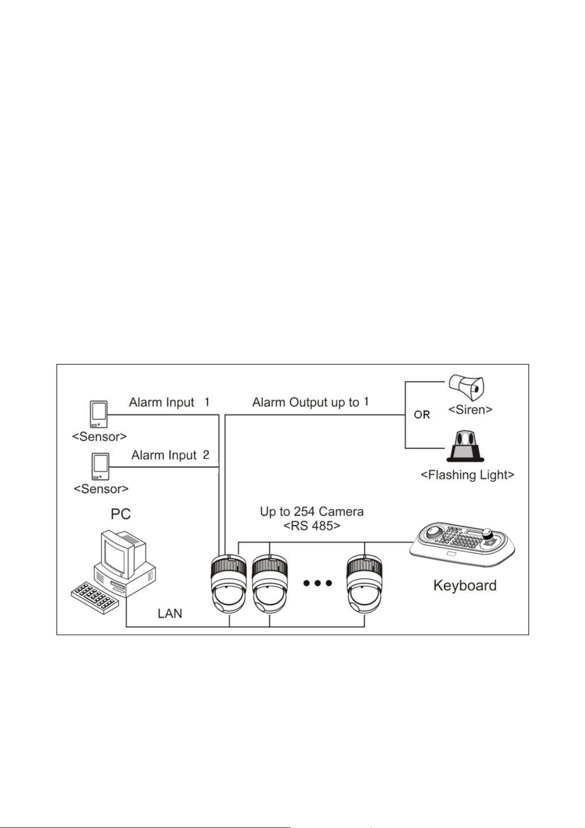
Figure 1. Typical System Configuration ......................................................................................14
Figure 2. Assemble bubble ring ass’y(Optional)...........................................................................15
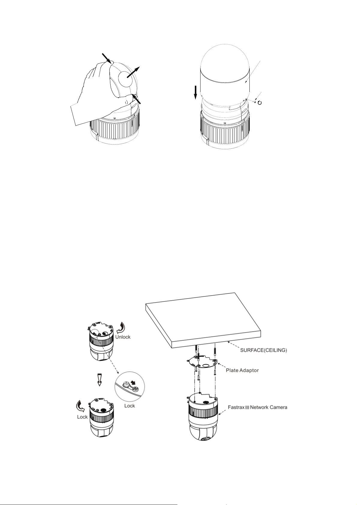
Figure 3. Installation.................................................................................................................15
Figure 4. Dimension..................................................................................................................16
Figure 5. Basic installation diagram............................................................................................17
Figure 6. Layout of Switches .....................................................................................................18
Figure 7. Setting Network Dome Camera Termination.................................................................18
Figure 8. Termination Diagram ..................................................................................................19
Figure 9. Main Menu .................................................................................................................23
Figure 10. Main Live View Page .................................................................................................24
Figure 11. Playback View ..........................................................................................................26
Figure 12. Basic Configuration ...................................................................................................29
Figure 13. Basic Configuration / Users........................................................................................30
Figure 14. Basic Configuration / User / Add User ........................................................................31
Figure 15. Basic Configuration / User / Modify User ....................................................................32
Figure 16. Basic Configuration / Network ...................................................................................33
Figure 17. Basic Configuration / Image ......................................................................................35
Figure 18. Basic Configuration / Audio .......................................................................................37
Figure 19. Basic Configuration / Date & Time .............................................................................39
Figure 20. Live View / Source ....................................................................................................41
Figure 21. Video & Image / Image - Basic ..................................................................................44
Figure 22. Video & Image / Image – Auto Exposure ...................................................................46
Figure 23. Video & Image / Image – Auto Focus ........................................................................49
Figure 24. Video & Image / Image – White Balance ....................................................................51
8
Page 9

Figur
e 25. Video & Image / Image – Privacy Mask ......................................................................53
Figure 26. Video & Image / Stream1.......................................................................................... 55
Figure 27. Video & Image / Stream2.......................................................................................... 58
Figure 28. Video & Image / Stream2 ROI Setting........................................................................ 60
Figure 29. Video & Image / Stream3.......................................................................................... 61
Figure 30. Video & Image / Stream3 ROI setting ........................................................................63
Figure 31. Video & Image / Stream4.......................................................................................... 64
Figure 32. Video & Image / Stream4 ROI Setting........................................................................ 67
Figure 33. Video & Image / Webcasting .....................................................................................68
Figure 34. Audio / Basic ............................................................................................................69
Figure 35. Event / Event In – Alarm In.......................................................................................71
Figure 36. Event / Event In – Manual Trigger .............................................................................73
Figure 37. Event / Event In – VMD Stream1 ...............................................................................74
Figure 38. Event / Event In – VMD Stream3 ...............................................................................76
Figure 39. Event / Event In – VMD Stream4 ...............................................................................78
Figure 40. Event / Event Out – SMTP (Email) .............................................................................80
Figure 41. Event / Event Out – FTP & JPEG. ...............................................................................82
Figure 42. Event / Event Out – HTTP Server...............................................................................84
Figure 43. Event / Event Out – Audio Alert. ................................................................................85
Figure 44. Event / Event Out – Audio Alert / Audio Recorder ....................................................... 86
Figure 45. Event / Event Out – Audio Alert / ARecoder window ...................................................87
Figure 46. Event / Event Out – Audio Alert / Encode Setup .........................................................87
Figure 47. Event / Event Out – PTZ Preset .................................................................................88
Figure 48. Event / Event Out – Record .......................................................................................89
Figure 49. Event / Event Map ....................................................................................................91
Figure 50. Event / Event Map – Add...........................................................................................93
9
Page 10

Figur
e 51. Dome Configuration / Auto Scan................................................................................95
Figure 52. Dome Configuration / Auto Scan / PTZ Control Panel ..................................................96
Figure 53. Dome Configuration / Preset .....................................................................................99
Figure 54. Dome Configuration / Tour ...................................................................................... 101
Figure 55. Dome Configuration / stored PTZ function list........................................................... 102
Figure 56. Dome Configuration / Pattern .................................................................................. 104
Figure 57. Dome Configuration / OSD ...................................................................................... 106
Figure 58. Dome Configuration / Home .................................................................................... 107
Figure 59. Dome Configuration / Motor Setup........................................................................... 108
Figure 60. Dome Configuration / View Angle ............................................................................109
Figure 61. Dome Configuration / System Menu ......................................................................... 111
Figure 62. Dome Configuration / RS485 ................................................................................... 113
Figure 63. System / Security – Users ....................................................................................... 114
Figure 64. System / Security / Users – Add User ....................................................................... 115
Figure 65. System / Security / Users – Modify User ................................................................... 116
Figure 66. System / Security – HTTPS...................................................................................... 117
Figure 67. System / Security – IP Filtering................................................................................ 119
Figure 68. System / Date & Time............................................................................................. 120
Figure 69. System / Network – Basic........................................................................................ 122
Figure 70. System / Network – DDNS ......................................................................................124
Figure 71. System / Network – RTP .........................................................................................126
Figure 72. System / Network – UPnP ....................................................................................... 128
Figure 73. System / Network – QoS ......................................................................................... 129
Figure 74. System / Network – Bonjour.................................................................................... 131
Figure 75. System / Network - Zeroconf ................................................................................... 132
Figure 76. System / Language ................................................................................................. 133
10
Page 11

Figur
e 77. System / Maintenance............................................................................................. 134
Figure 78. System / Support.................................................................................................... 136
Figure 79. About.....................................................................................................................137
11
Page 12

DESCRIPTION
-------------------------------------------------------------------------------------------------------------------------------------
The IPSD202MT camera is an internet protocol based megapixel network camera with a built-in
web based viewer on Internet Explorer
applications and compatible with supplied Utility software for easy installation and Client software to
search, configure, manage, live view, record and playback.
The camera supports dual compression formats and multiple streaming simultaneously. The two
standard compression formats include H.264 and MJPEG. The multiple streams can be configured to
a variety of resolutions, bit rates and frame rates.
The camera uses 1/2.8 inch CMOS sensor and Focal length 4.7~94mm lens and also supports PoE
(Power over Ethernet), DC12V, and AC24V.
Models
IPSD202MT 2 Megapixel, NTSC(PAL)
®
. The camera has a connection feature for third-party
Key Features
HDTV Video Quality
The IPSD202MT is capable of providing the outstanding image quality with HDTV performance and
profiles (High, Main, and Baseline) in H.264 compression.
Multiple Streaming
Each stream can be programmed independently and transmitted using different configurations.
ROI (Region of Interest)
The ROI features that transmit specially selected area in the primary stream using different FPS,
Resolution, Bit Rates and Picture Quality.
Dual Codec (H.264, MJPEG)
The IPSD202MT supports two standard compressions formats H.264 and MJPEG.
Built-in optical Zoom
Support maximum 20x optical and 12x digital zoom. (Total 240x Zoom).
Intelligent Video Motion Detection
The IPSD202MT offers intelligent & sophisticated video motion detection for each multiple streams.
12
Page 13

Trip
This camera supports Power over Ethernet (PoE), which supplies power to the camera through the
network. If the network has no PoE, connect a DC12V or AC24V power connector.
Day and Night
The IPSD202MT provide clear monitoring images even in low light conditions using IR-cut filter.
le Power (Power over Ethernet, DC12V, AC24V)
SD Local Recording
The IPSD202MT provides local video recording function. When camera detects video motion or
alarm events or manual trigger, it can record video stream by itself.
Voice Alert Linked to Alarm Detection
The IPSD202MT can play the audio file stored in the camera in synchronization with alarm detection
by the sensor input or the motion detection function.
Network Flow Control
The IPSD202MT provides a flow control function which enhances network efficiency by significantly
restricting user video streams with designating the maximum bandwidth.
ONVIF Certificate
The IPSD202MT network camera complies with the ONVIF certificate. ONVIF (Open Network Video
Interface Forum) is an open industry forum for the development of a global standard for the
interface of network video product.
Components
Quantity Description
1 Camera
1 Bubble Ring
3 Assembly Screws for Attaching Network Dome Camera
1 Installation CD
3 Plastic Anchor
NOTE
Adapter for DC12V / AC24V are not supplied.
13
Page 14
INSTALLATION
-------------------------------------------------------------------------------------------------------------------------------------
Before Installation
Before installing the camera, thoroughly familiarize yourself with the information in this section of
the manual.
- Recommend connecting the camera to a network that uses a DHCP (Dynamic Host Configuration
Protocol) server to address devices.
- To ensure secure access to the IP camera, place the camera behind a firewall when it is
connected to a network.
Starting Installation
Base Installation
Figure 1. Typical System Configuration
14
Page 15
push
bubble ring ass'y
remove camera window
screw
push
remove window
assemble bubble ring ass'y
Figure 2. Assemble bubble ring ass’y(Optional)
NOTES
It is recommended to remove camera window for improving picture quality when you use bubble
ring assy.
The Network Dome Camera is for use in surface mounting applications and the mounting surface
should be capable of supporting loads up to 10lb (4.5kg).
The Network Dome Camera’s base should be attached to a structural object, such as hard wood,
wall stud or ceiling rafter that supports the weight of the Network Dome Camera.
Figure 3. Installation
15
Page 16
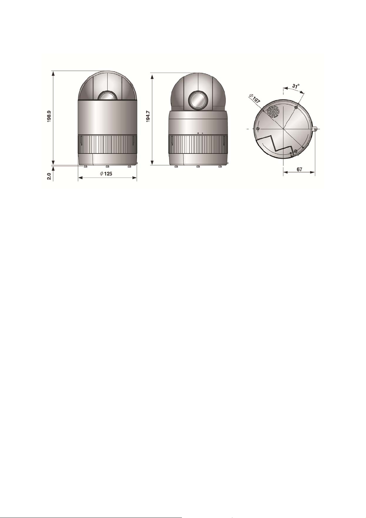
Figure 4. Dimension
16
Page 17
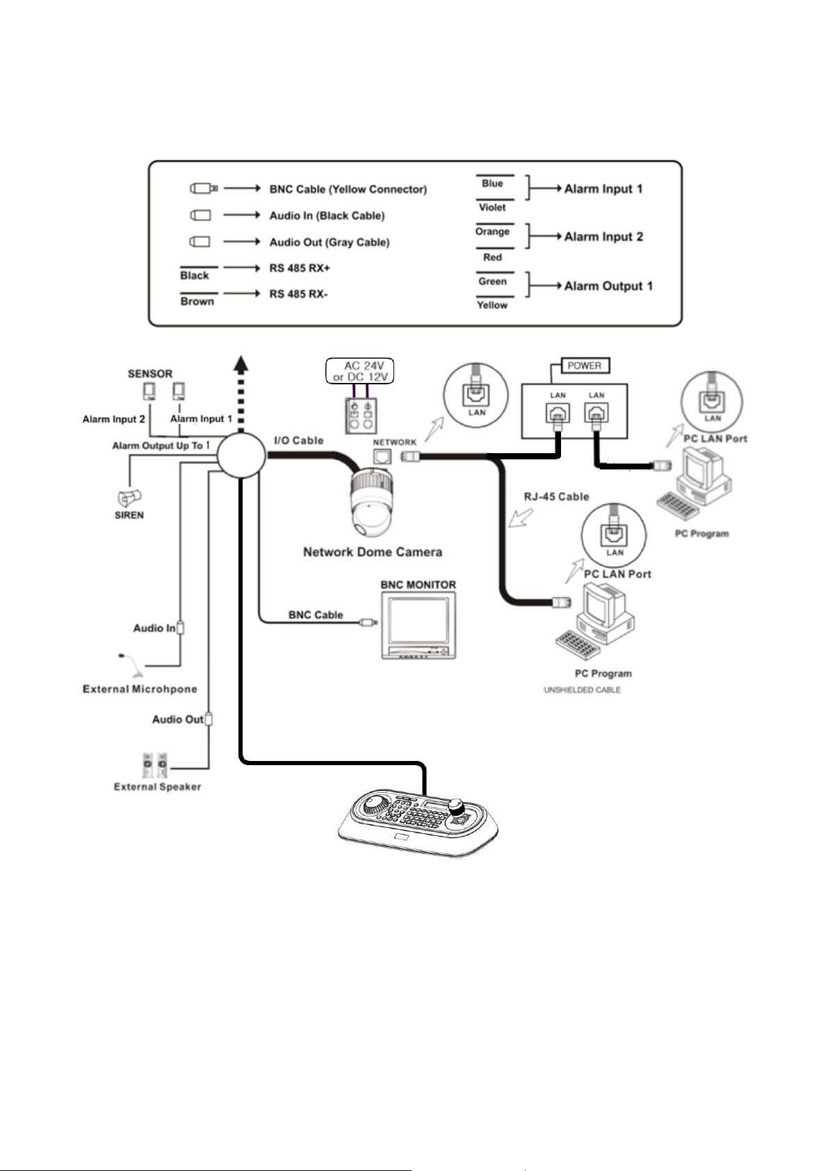
Basic Configuration of Fastrax X20 Network Dome Camera System
Figure 5. Basic installation diagram
17
Page 18
The Network Dome Camera must be installed by qualified service personnel in accordance with all
local and federal electrical and building codes. The system should be installed according to Figures
5 through 8.
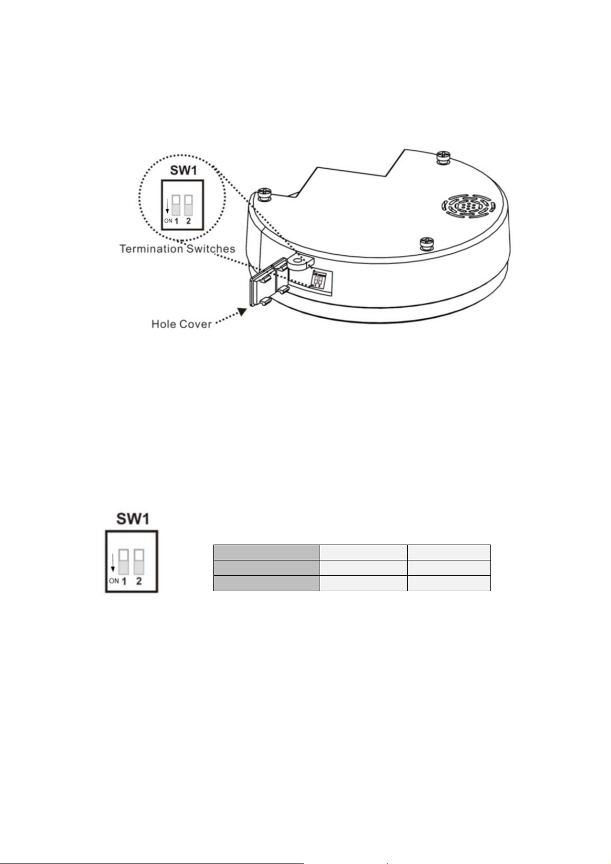
Figure 6. Layout of Switches
Setting Network Dome Camera Termination
The device which is connected at end of line, whether it is a Network Dome Camera or keyboard
controller, must have the cable for communication terminated by setting the appropriate DIP switch.
Without proper termination, there is potential for control signal errors. Total length of the cable for
communication should not exceed 1.2km (4000ft).
Figure 7. Setting Network Dome Camera Termination
SW1 1 2
Terminated ON RESET
Not terminated OFF OFF
Reset
Restore the camera’s factory default settings. The dip switch 2 is on for 15s and then off.
Please take steps as follows:
1. Power off
2. Press the switch 2 to On
3. Supply the camera with power
4.
wait for 15 seconds and relocated SW2 off
18
Page 19
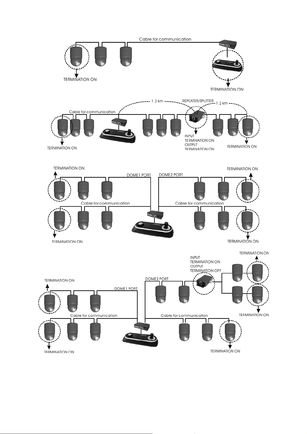
Figure 8. Termination Diagram
19
Page 20

Setting Network Dome Camera Address (ID)
To prevent damage, each Network Dome Camera must have a unique address (ID). When
installing multiple Network Dome Cameras using a multiplexer, it is suggested that the Network
Dome Camera address match the multiplexer port number.
If you want to set the address more than 999, you should contact the service provider.
Refer to ‘Dome Configuration - RS485’ section for detailed information.
Setting Network Dome Camera Protocol
If a Network Dome Camera is to be installed with a Fastrax keyboard controller, select the default
protocol.
Consult service personnel if a Network Dome Camera is installed with device other than a keyboard
controller.
Refer to ‘Dome Configuration - RS485’ section for detailed information.
Connections
Connecting to the RS485
The Network Dome Camera can be controlled remotely by an external device or control system,
such as a control keyboard, using RS485 half-duplex serial communications signals. Connect Marked
Rx+, Rx- to Tx+ and Tx- of the RS485 control system.
Connecting Video out connector
Connect the video out (BNC) connector to the monitor or video input.
Connecting Alarms
-
AL1 to 2 (Alarm In)
You can use external devices to signal the Network Dome Camera to react on events.
Mechanical or electrical switches can be wired to the AL (Alarm In) and GND (Ground)
connectors.
-
GND(Ground)
Connect the ground side of the Alarm input and/or alarm output to the GND connector.
-
NC (NO) (Normal Close or Normal Open: Alarm Out)
The Network Dome Camera can activate external devices such as buzzers or lights. Connect the
device to the NC (NO) (Alarm Out) and COM (Common) connectors.
20
Page 21

Connecti
The Network Dome Camera supports the operation through the network. Therefore, it is necessary
to connect a standard RJ-45 cable to it. Generally a cross cable is used for directly connection to PC,
while a direct cable is used for connection to a hub.
Connecting the Power
Connect the power of DC 12V to the Network Dome Camera.
Use certified / Listed Class 2 power supply transformer only.
ng the Network
Setting Network Dome Camera Protocol
When a camera, Encoder or Decoder is first connected to the network it has no IP address. So, it is
necessary to allocate an IP address to the device with the “Smart Manager” utility on the CD.
Micro SD Card Installation (Optional)
Insert Micro SD card for local recording.
21
Page 22

OPERATION
-------------------------------------------------------------------------------------------------------------------------------------
Before starting the camera, installation must be complete. The camera completes a configuration
sequence within approximately 40 seconds when power is supplied. The amber LED of this
megapixel camera flash one time per second indicating the configuration sequence is complete.
NOTES
- If the DHCP is enabled but the camera is not connected to a DHCP server, the camera will be set
default IP 192.168.30.220 and try to get IP from DHCP server about every two seconds.
- Network and processor bandwidth limitations might cause the video stream to pause or appear
pixilated when an increased number of Web-interface users connection to the camera. Decrease
the images per second, resolution, compression, or bit rate settings of the Web-interface video
streams to compensate for network or processor limitations.
Minimum conditions for using web browser
The minimum system requirements to use a Web browser with this IP camera are as follows:
®
- CPU: Pentium
- Operational System: Windows XP
- System Memory: RAM 512 Mbyte
- Ethernet: 100 Mbit
- Video Resolution: 1024(Horizontal) x 768(Vertical) pixels or higher
- Internet Explorer
®
- ActiveX
1.0.0.13 or later
4 microprocessor, 2.0GHz
®
or Windows Vista® or Windows 7®
®
7 or later
Accessing the IP camera
1. Open Web browser
- Double click Internet Explorer
2. Type IP address
- Type the camera’s IP address in the Internet Explorer
- The default IP address is
NOTES
- If you do not know the camera’s IP address, install the SmartManager® utility software available
on the CD supplied with the product. The utility software will locate the assigned Model name,
Host name, MAC address, IP address, Version and others.
- Refer to the SmartManager
®
icon.
®
address bar.
192.168.30.220
®
utility software manual for more detail.
22
Page 23
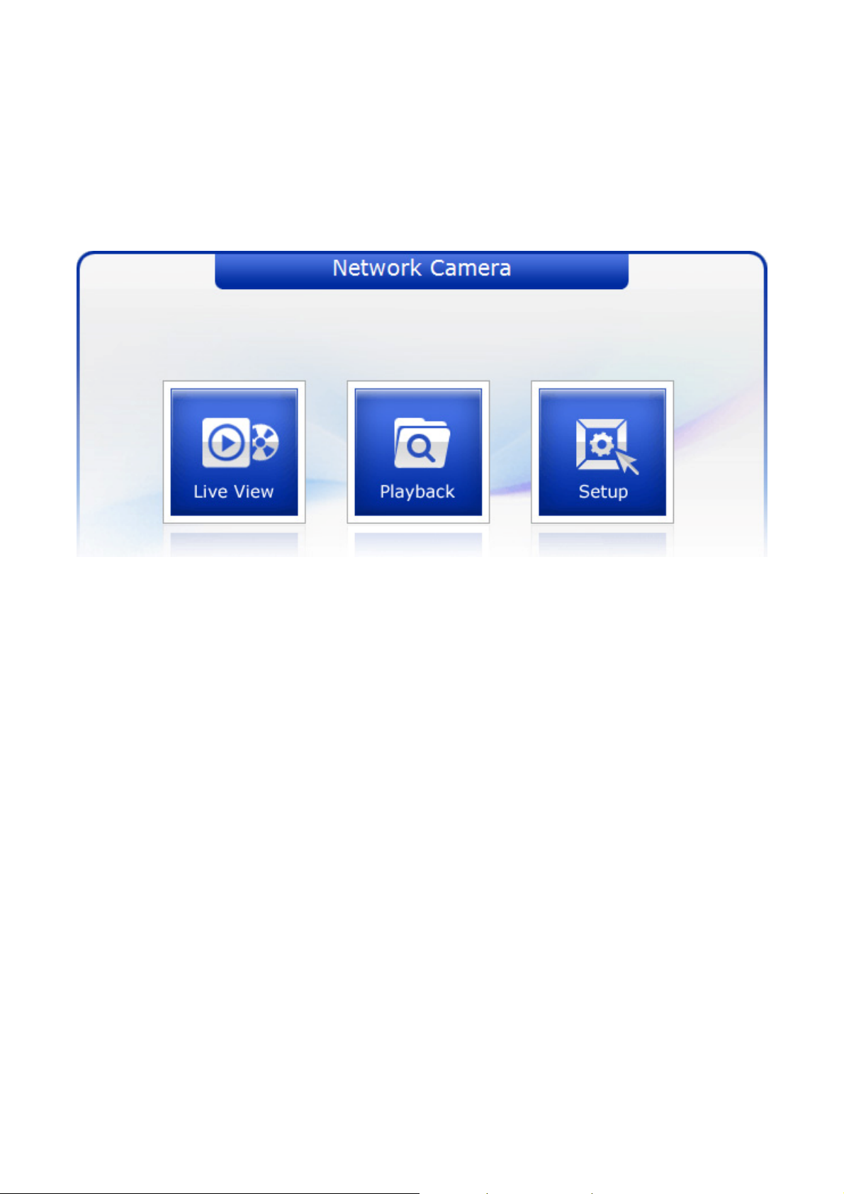
3. L
og On to the camera
- Click the Live View icon for default live image view or the Setup icon to change the configuration
values.
Main Menu
Figure 9. Main Menu
The dialog box will be appears.
- Type User ID and Password in the dialog box. The default User ID and Password are
admin
NOTE
For security purposes, be sure to change the password after you log on for the first time.
.
23
Page 24
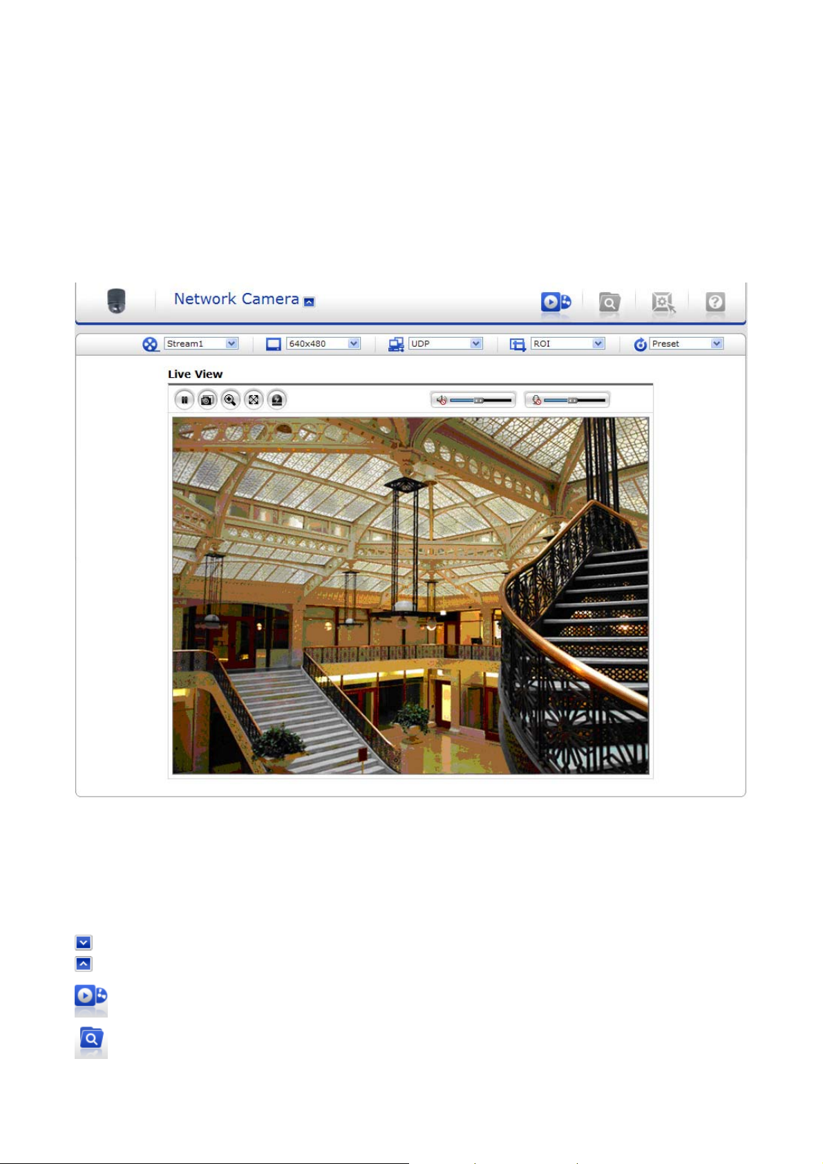
LIVE VIEW
-------------------------------------------------------------------------------------------------------------------------------------
The Live View page provides you to select the properties of video source. You can view the live
image from this page and also access the Setup menu and operate the main functions.
Figure 10. Main Live View Page
Live Video Page Icons
Hide Main Icons: Hides main icons in the live view page.
Show Main Icons: Shows main icons in the live view page.
Live view: Displays live video stream.
Playback View: Enters playback menu.
24
Page 25
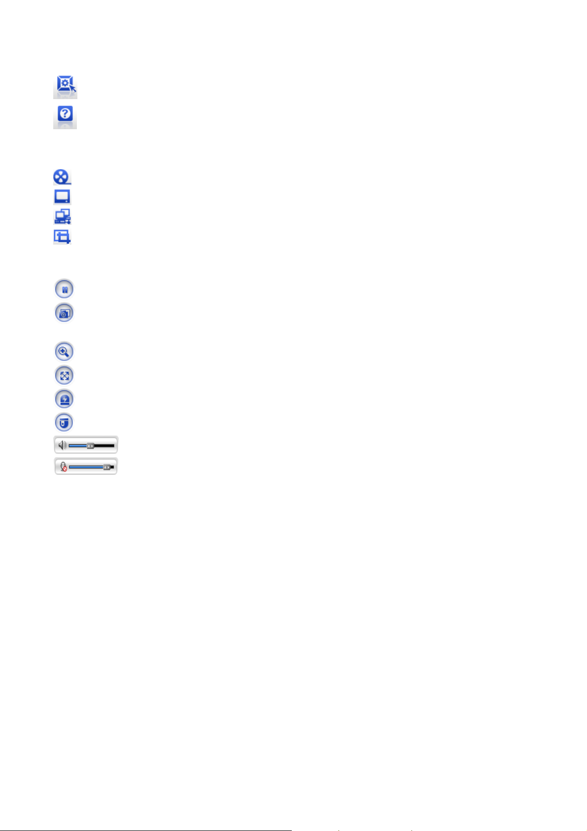
Setup: Enters setup menu.
Help: Shows helpful information.
Source: Specify the viewable video stream source to display in live view page.
View Size: Specify the viewable video size to display in live view page.
Stream Type: Specify the internet protocol to display in live view page.
ROI View: Specify the specially selected area to transfer using different stream feature in the
primary video image. ROI is an abbreviation for “Region of Interest”.
Pause: Pause the live video stream.
Snapshot: Take a picture of the video image currently on display. Supports the origin image
size view, Print, and Save feature.
Digital Zoom: Supports a digital zoom in live video image.
Full Screen: Expands video image to the entire screen area.
Manual Trigger: Activates the Alarm Out signaling manually.
PTZ Control: Activates PTZ Control Panel
Speaker: Adjusts the volume of Speaker and switch the sound on / off.
Microphone: Adjusts the volume of Microphone and switch the sound on /
off.
25
Page 26
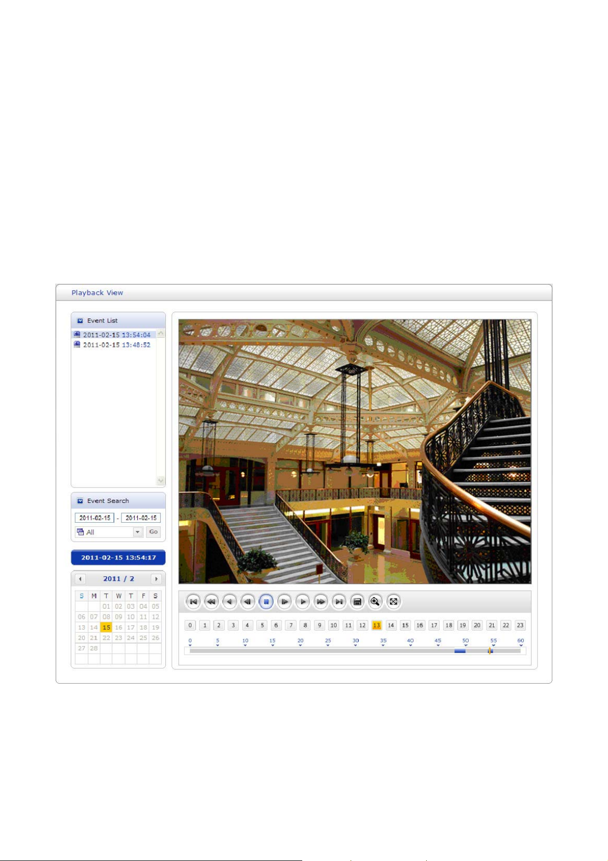
PLAYBACK
-------------------------------------------------------------------------------------------------------------------------
This Playback page provides current SD recorded file lists and information. It also supports easy
access and how to playback the recorded stream.
Playback View
User can access the recorded image in the web browser.
Figure 11. Playback View
Event List: Shows the recorded lists by Alarm, Trigger and Motion event.
26
Page 27
Event Search: Select the start date and end date you want to playback, and then click the Go
button to show the list. In case of you want to list up according to event type, click the arrow
button and select event type.
Calendar: Shows the information about playback image.
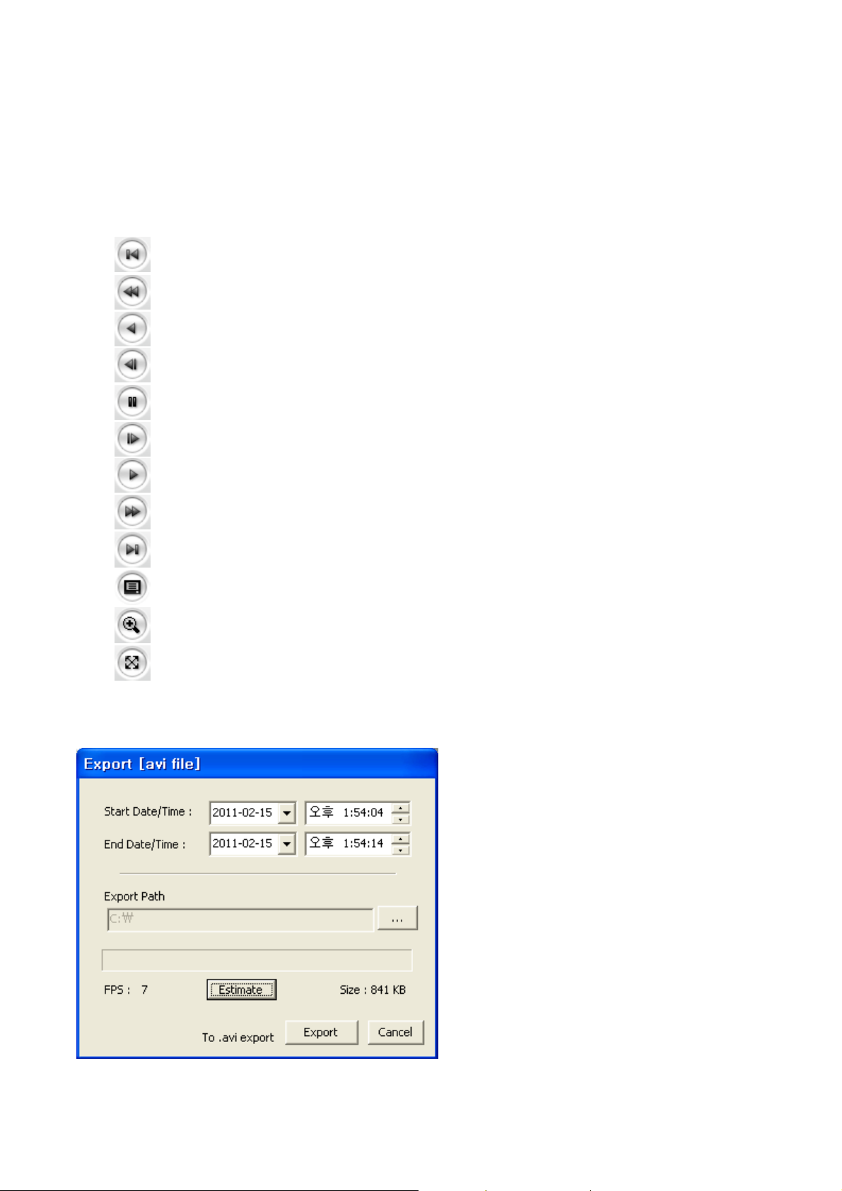
Playback Control Buttons: Provides user favorite functions.
Go to the first.
Fast backward play
Backward play
Backward step
Pause
Forward step
Forward play
Fast forward play
Go to the last
Clip copy
Digital Zoom
Full Image
Clip Copy: Provides avi format file.
27
Page 28
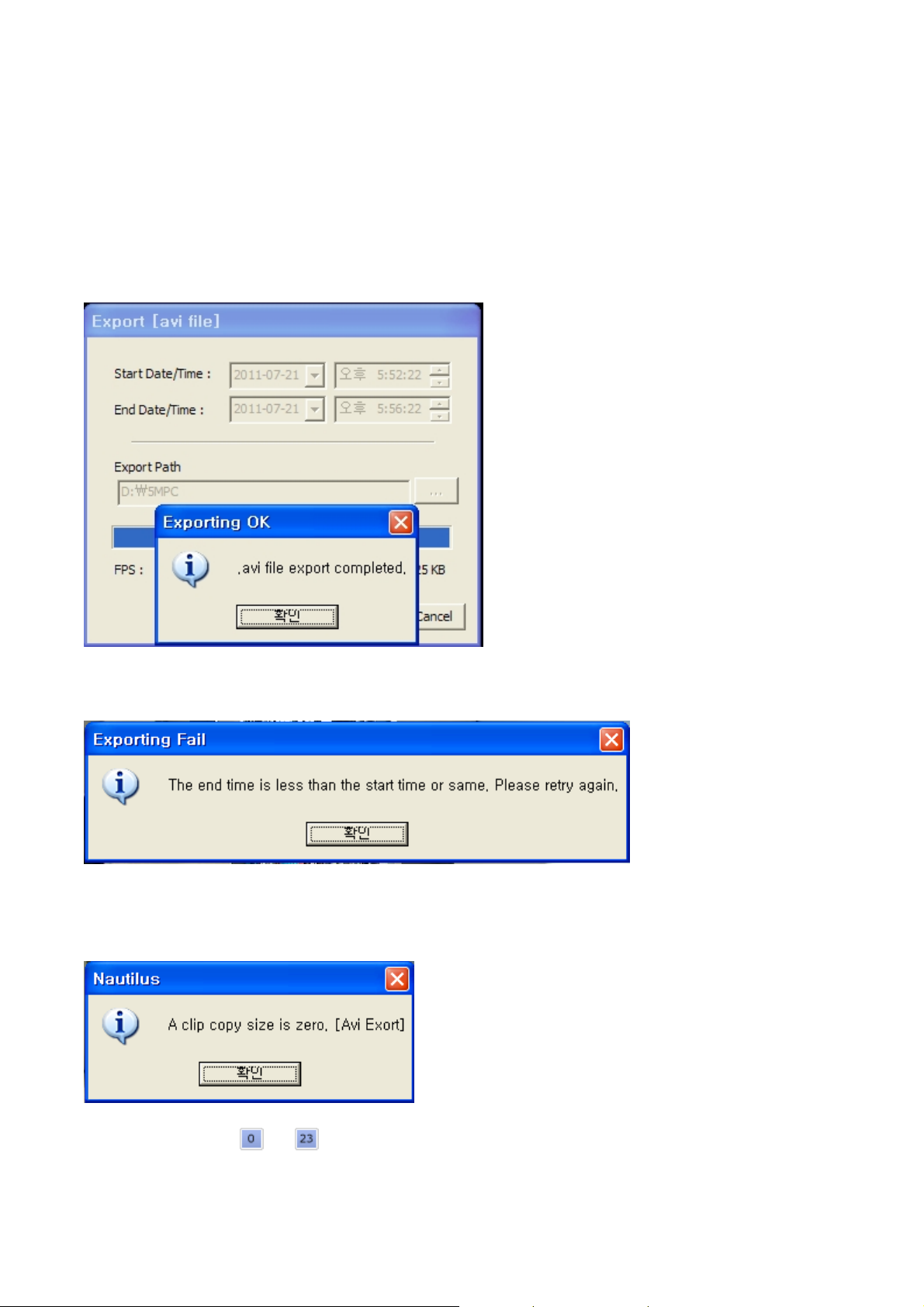
Please step
1. Select Start Date/Time and End Date/Time.
2. Set Export Path.
3. Click Estimate button which is shown the file FPS and Size.
4. Click Export or Cancel button.
as follows;
NOTES
1. If you set successfully, the following pop-up windows will be appeared.
2. In case of mismatching of the Start or End Date/Time, the following windows will be appeared.
Please retry to set the Start or End Date/Time.
3. In case of no image data between the Start Date/Time and End Date/Time, the following
windows will be appeared.
Please retry to set the Start or End Date/Time.
4. The buttons from
to indicate an Hours and the number from 0 to 60 indicate a minutes.
28
Page 29
SETUP
-------------------------------------------------------------------------------------------------------------------------------------
The SETUP pages provide you to manage the camera and change the setting values. For the easy
and quick access the video, the setup menu is configured two parts, which are Basic Configuration
and advanced configuration. The Basic Configuration menu allows you to setup Users, basic
Network and Image. The remaining configuration parts help to setup user dependent values and
provide more advanced settings.
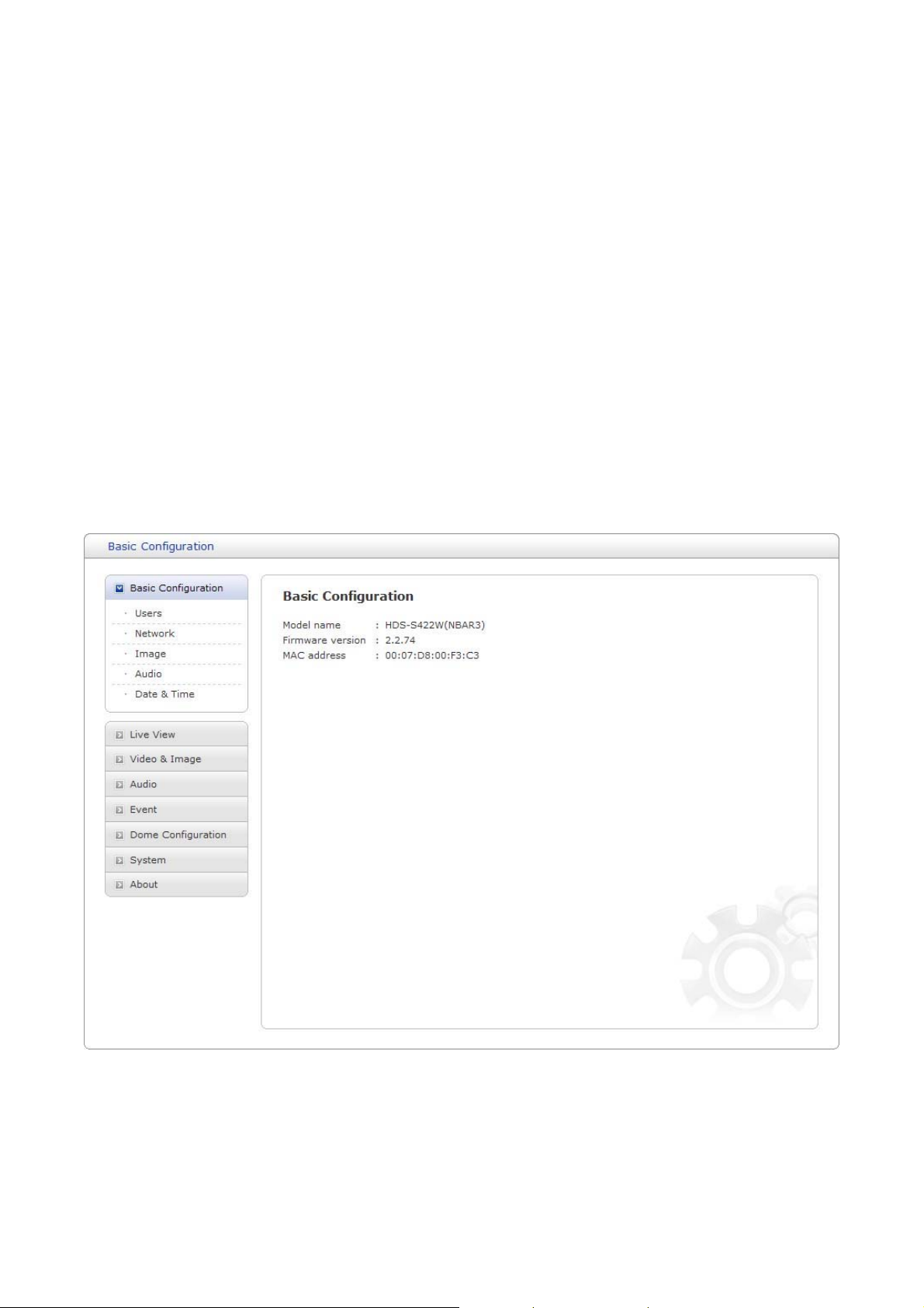
Basic Configuration
Basic Configuration supply user to access the camera image using minimum setting. Also it shows
the camera basic information such as Model name, Firmware version and MAC address.
Figure 12. Basic Configuration
29
Page 30
NOTE
The setting menu might not be available if the user does not have the permission to access this
feature. The only required setting is the IP address, which is set on the Network page. All other
settings are available with default values and optional.
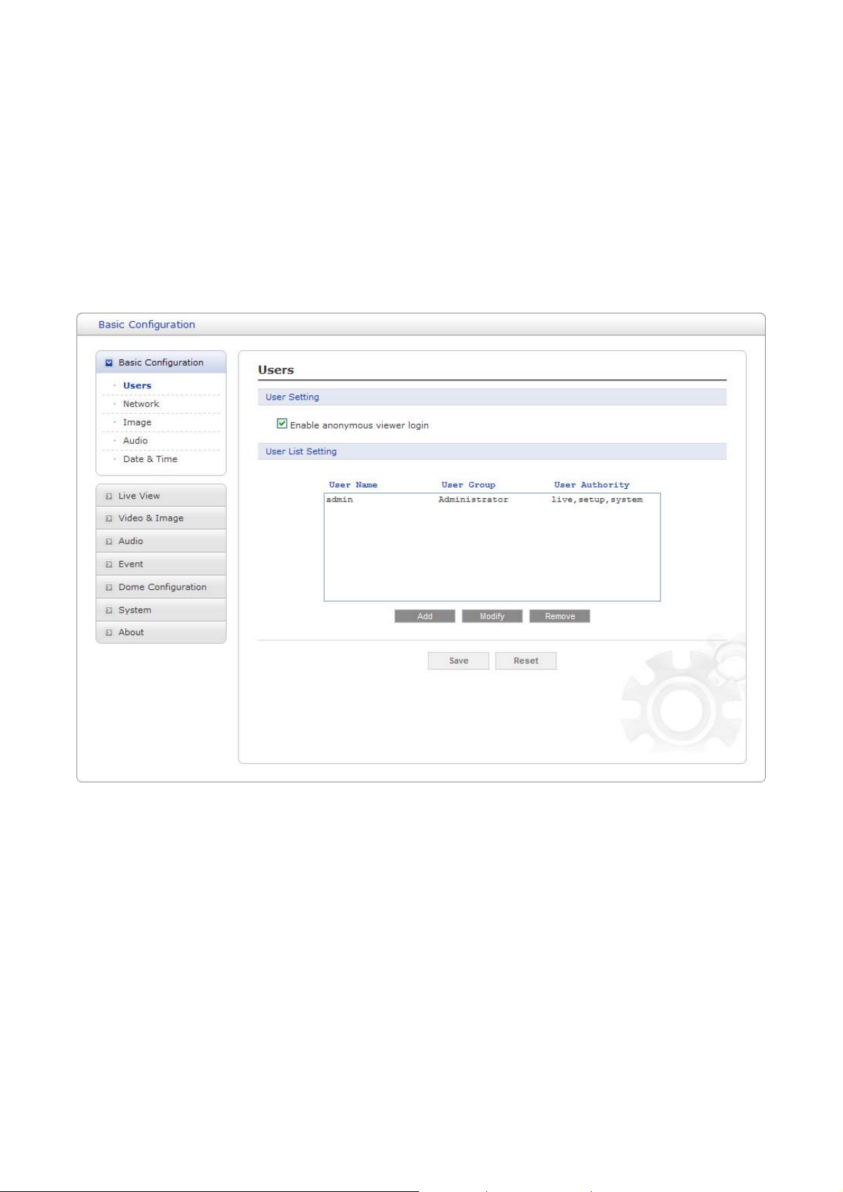
Users
Use the Users tab to manage user permission to access the camera.
Figure 13. Basic Configuration / Users
User Setting: Click the Enable anonymous viewer login checkbox to enable anonymous user
login to the camera. The default setting is disabled.
User List Setting: User accounts can be added or modified or removed. The authority
depends upon user group automatically and shows the permission status to access the menus.
The default user name / password is
User Name: Shows the name which registered to access the camera.
User Group: Shows the assigned permission given to users.
Authority: Shows the permission status to access the menus.
admin
.
30
Page 31

- Click t
he Add, Modify, or Remove button for managing user account.
Figure 14. Basic Configuration / User / Add User
To add a new user:
1. Click the Add tab, and then new pop-up window appears.
2. Click in the User name box and type a new user name (1 to 14 alphanumeric characters). User
names are not case sensitive.
3. Click in the Password box and type a password (1 to 8 alphanumeric characters). Passwords are
case sensitive.
4. Click in the Confirm password box and retype a password.
5. Click in the User group box and select one of the groups you wish to assign to the user.
6. Click the OK button to save the settings and add a new user.
31
Page 32

Figure 15. Basic Configuration / User / Modify User
To modify a user:
1. Select one of the User Name in the User List Setting you want to modify.
2. Click the Modify tab, and then new pop-up window appears.
3. Click in the Password box and type a password (1 to 8 alphanumeric characters). Passwords are
case sensitive.
4. Click in the Confirm password box and retype a password.
5. Click in the User group box and select one of the groups you wish to assign to the user.
6. Click the OK button to save the settings and modify a user.
NOTE
The user name can’t be modified.
To remove a user:
1. Select one of the User Name in the User List Setting you want to remove.
2. Click the Remove tab. A dialog box appears with confirmation message.
3. Click the OK button. The user profile is removed from the User List Setting profile.
NOTE
The admin user name can’t be modified.
- Click the Save button to save the settings, or click the Reset button to clear all of the information
you entered without saving it.
32
Page 33

Network
Use the Network tab to manage basic network settings.
Figure 16. Basic Configuration / Network
IP Address Configuration: The DHCP (Dynamic Host Configuration Protocol) server has a
feature that automatically assigns an IP address to the device if there is a device on the network.
Obtain IP address via DHCP: Select the choice box if you want to assign the IP address from
DHCP server automatically, and then the remaining setting are read-only text.
Use the following IP address: Select the choice box if you want to assign the IP address
manually.
IP address: The address of the camera connected to the network. Specify a unique IP address
for this network camera.
Subnet mask: The address that determines the IP network that the camera is connected to
(relative to its address). Specify the mask for the subnet the network camera is located on.
Default router: The router that accesses other networks. Specify the IP address of the default
router (Gateway) used for connecting devices attached to different networks and network segments.
IPv6 Address Configuration: Check the Enable IPv6 check-box to enable IPv6 address
configuration. Other settings for IPv6 are configured in the network router.
33
Page 34

DNS Configuration: DNS (Domain Name Service) provides the translation of host names to IP
addresses on your network.
Obtain DNS server via DHCP: Select the choice box if you want to use the DNS server
settings provided by the DHCP server automatically, and then the remaining setting are read-only
text.
Use the following DNS server address: Select the choice box if you want to use the desired
DNS server manually.
Domain name: Enter the domain to search for the host name used by the network camera.
Primary DNS server: Enter the IP address of the primary DNS server.
Secondary DNS server: Enter the IP address of the secondary DNS server.
- Click the Save button to save the settings, or click the Reset button to clear all of the information
you entered without saving it.
34
Page 35

Image
Use the Image tab to adjust the camera image setting value and orientation.
Figure 17. Basic Configuration / Image
35
Page 36

Image Appearance: The image appearance allows you to adjust the camera setting
parameters and change the camera orientation. All of parameters are recommended to be
modifying for good image quality suitable for installation place.
Brightness: Controls the brightness of detail in a scene. The brightness can be adjusted in the
range -7~7. The default setting is 0.
Sharpness: Controls the clarity of detail in a scene. The sharpness can be adjusted in the range
0~15. The default setting is 10.
Gain limit: Set a limit of gain when image signal-to-noise ratio is particularly important.
Custom gamma: Change the gamma correction. Blocked-up shadows in images will be more
noticeable than usual. The default setting is Standard.
Chroma: Configure a chroma suppress mode for low-illumination conditions. This can be useful
when color noise is particularly noticeable in such conditions. The default setting is Middle.
Enable flip image: Rotate the camera image 180 degrees vertically.
Preset freeze: The image is frozen during calling preset.
Noise reduction Control: The NR(Noise Reduction) function removes noise to provide
clearer images. In bright conditions, changing the NR level will not have an effect.
Level: The level can be adjusted in the range 1-5 and off. The default setting is 4.
Moving Level: The level can be adjusted in the range 1-5 and off when Pan and Tilt are moving.
The default setting is 4.
Day & Night Control: Day & Night controls the position of the IR (Infra Red) cut filter, which
determines the color or block-white setting of the camera.
Threshold: Select the change level of switching from night to day mode in auto.
Digital Zoom Control: The digital zoom control allows you to control the digital zoom.
Digital zoom: The digital zoom can be adjusted in the range off-Max. The default setting is off.
Off Zoom range is limited to the optical.
x2 Zoom is extendable 2x of digital zoom range.
x4 Zoom is extendable 4x of digital zoom range.
Max Zoom is extendable Max digital zoom range.
- Click the Save button to save the settings, or click the Reset button to clear all of the information
you entered without saving it.
36
Page 37

Audio
Use the Audio tab to manage the basic audio settings for the camera.
Figure 18. Basic Configuration / Audio
Audio Setting: Click the Enable audio checkbox to enable audio. This page describes how to
configure the basic audio settings for the camera. This camera supports the audio full duplex that
can be transmits and receives audio in both directions at a time.
Compression type: G.711 is the international standard for encoding wired-telephone audio on
64kBit/s channel. It is a PCM (Pulse Code Modulation) scheme operating at 8 kHz sample rate. The
default setting is G.711 µ-law.
Sample rate: Indicates the number of times per second the sound is sampled. The default
setting is 8 kHz.
NOTE
G.711, also known as Pulse Code Modulation (PCM), is a very commonly used waveform codec.
G.711 uses a sampling rate of 8,000 samples per second, with the tolerance on that rate 50 parts
per million (ppm). Non-uniform quantization (logarithmic) with 8 bits is used to represent each
sample, resulting in a 64 kbit/s bit rate. There are two slightly different versions; μ-law, which is
used primarily in North America, and A-law, which is in use in most other countries outside North
37
Page 38

America. G.711 μprovides more quantization levels at lower signal levels.
law tends to give more resolution to higher range signals while G.711 A-law
Audio Input: Adjusts the audio volume especially from the Mike.
Input volume: The Input volume can be adjusted in the range from -21.00 to 21.00 dB. The
default setting is 0 dB. Click the Mute box if you do not want the audio input.
Audio Output: Adjusts the audio volume especially to the Speaker.
Enable full duplex: Enable audio out.
Output volume: The Output volume can be adjusted in the range from -18.1 to 6.0 dB. The
default setting is 0 dB. Click the Mute box if you do not want the audio output.
- Click the Save button to save the settings, or click the Reset button to clear all of the information
you entered without saving it.
38
Page 39

Date & Time
Use the Date and Time tab to set the camera’s date and time by manually or automatically.
Figure 19. Basic Configuration / Date & Time
Current Server Time: Shows the current date and time.
Date: The default setting is 1970-01-01.
Time: The default setting is 00:00:00.
New Server Time: Select the time zone where your camera is located.
Click the "Automatically adjust for daylight saving changes" checkbox to automatically update the
time changes caused by daylight saving.
Time zone: The default setting is GMT.
Time mode: The default setting is Set manually.
Synchronize with computer time: Sets the time according to the clock on your computer.
39
Page 40

Synchronize with NTP Server: This option will obtain the correct time from an NTP server
every 60 minutes. The NTP server's IP address or host name is specified in the time server.
Set manually: Using this option allows you to manually enter the date and time.
Date & Time Format: Select one of the Date and Time format.
Date Format: The default setting is YYYY-MM-DD.
Time Format: The default setting is 24 hours.
- Click the Save button to save the settings, or click the Reset button to clear all of the information
you entered without saving it.
40
Page 41

Live View
Use the Source tab to configure the live view video source and composite video output properties.
Source
Configure the default live view source in the web browser and composite video output source.
Figure 20. Live View / Source
View Size: Select which formats do you want as default live view source.
Enable cookie: Click the Enable cookie box if you want to reload the last configuration settings.
Use the followings: Click the Use the following box to configure the video properties to be
displayed in the live view page.
Source: Select one of the stream sources to be displayed in the live view page. The default setting
is Stream1.
View size: Select one of the view sizes to be displayed in the live view page. The default setting
is a 1280x720.
Stream type: Select one of the stream protocols. The default setting is UDP.
41
Page 42

Default TV out: Configure the composite video output properties.
Mode: Check the composite video output format.
Source: Select one of the composite video output sources. The default setting is stream1.
Sequence If you select Sequence, the composite video output repeats the video
images on a single video pane according to <Sequence Mode Setting>.
<Sequence Mode Setting>
Click the checkbox if you want to assign each stream into Sequence Mode.
Each stream dwell time shows the dwelling time / intervals of each stream when the stream set the
sequence mode.
Stream1 Dwell Time
Enter stream1 dwell time. The dwell time can be adjusted in
the range 3-3600 seconds. The default setting is 5 seconds.
Stream2 Dwell Time
Stream3 Dwell Time
Stream4 Dwell Time
- Click the Save button to save the settings, or click the Reset button to clear all of the information
you entered without saving it.
Enter stream2 dwell time. The dwell time can be adjusted in
the range 3-3600 seconds. The default setting is 5 seconds.
Enter stream3 dwell time. The dwell time can be adjusted in
the range 3-3600 seconds. The default setting is 5 seconds.
Enter stream4 dwell time. The dwell time can be adjusted in
the range 3-3600 seconds. The default setting is 5 seconds.
42
Page 43

Video & Image
Use the Video & Image tab to select a preset camera stream configuration or configure custom
video stream settings. The camera features multiple video streams with selectable settings for
Profile, Resolution, Bit rate control, Compression, and Frame rate. The default names for the
streams are Stream1, Stream2, Stream3, and Stream4. Although each stream can be programmed
independently, the settings of one stream can limit the options available for the other stream
depending on the processing power used.
NOTES
- H.264 is the new generation compression standard for digital video, also known as MPEG4 Part 10.
This function offers higher video resolution than Motion JPEG or MPEG4 at the same bit rate and
bandwidth, or the same quality video at a lower bit rate.
- MJPEG (Motion Joint Photographic Experts Group) is a simple compression technique for
networked video. Latency is low and image quality is guaranteed, regardless of movement or
complexity of the image. Image quality is controlled by adjusting the compression level, which in
turn provides control over the file size, and thereby the bit rate.
43
Page 44

Image – Basic
Use the Image-Basic tab to adjust the camera image setting values and orientation.
Figure 21. Video & Image / Image - Basic
44
Page 45

Image Appearance: The image appearance allows you to adjust the camera setting
parameters and change the camera orientation. All of parameters are recommended to be
modifying for good image quality suitable for installation place.
Brightness: Controls the brightness of detail in a scene. The brightness can be adjusted in the
range -7~7. The default setting is 0.
Sharpness: Controls the clarity of detail in a scene. The sharpness can be adjusted in the range
0~15. The default setting is 10.
Gain limit: Set a limit of gain when image signal-to-noise ratio is particularly important.
Custom gamma: Change the gamma correction. Blocked-up shadows in images will be more
noticeable than usual. The default setting is Standard.
Chroma: Configure a chroma suppress mode for low-illumination conditions. This can be useful
when color noise is particularly noticeable in such conditions. The default setting is Middle.
Enable flip image: Rotate the camera image 180 degrees vertically.
Preset freeze: The image is frozen during calling preset.
Noise reduction Control: The NR(Noise Reduction) function removes noise to provide
clearer images. In bright conditions, changing the NR level will not have an effect.
Level: The level can be adjusted in the range 1-5 and off. The default setting is 4.
Moving Level: The level can be adjusted in the range 1-5 and off when Pan and Tilt are moving.
The default setting is 4.
Day & Night Control: Day & Night controls the position of the IR (Infra Red) cut filter, which
determines the color or block-white setting of the camera.
Threshold: Select the change level of switching from night to day mode in auto.
Digital Zoom Control: The digital zoom control allows you to control the digital zoom.
Digital zoom: The digital zoom can be adjusted in the range off-Max. The default setting is off.
Off Zoom range is limited to the optical.
x2 Zoom is extendable 2x of digital zoom range.
x4 Zoom is extendable 4x of digital zoom range.
Max Zoom is extendable Max digital zoom range.
- Click the Save button to save the settings, or click the Reset button to clear all of the information
you entered without saving it.
45
Page 46

Image – Auto Exposure
Use the Auto Exposure tab to control the Auto Exposure.
Figure 22. Video & Image / Image – Auto Exposure
Exposure Control: Exposure is the amount of light detected by the camera sensor. A scene
with correct exposure settings has adequate detail and contrast between white and dark values. An
46
Page 47

image wit
auto and manual exposure settings.
h too little or too much exposure determines detail in the scene. The camera features
Exposure mode: Supports exposure modes to control the amount of light detected by the
camera sensor base on settings for light conditions. The default setting is Auto
Auto Automatic Exposure.
Manual Adjust the shutter, exposure and electronic shutter manually.
Manual Exposure Adjust the exposure manually.
Manual Shutter Adjust the electronic shutter manually.
Manual Bright
Adjust both gain and iris using an internal algorithm,
according to a brightness level freely set by the user.
Slow auto exposure: Slow auto exposure allows you to reduce the exposure response speed. It
allows you to lengthen the automatic exposure response speed from 1 second up to approximately
10 minutes.
Shutter speed: Select the electronic shutter speed. It’s only available when Exposure mode is a
Manual shutter mode and Manual mode.
Exposure: Select the Iris. It’s only available when Exposure mode is a Manual Exposure and
Manual mode. The Iris can be adjusted in the range F1.6-F14 and close. The default setting is F1.6.
AGC gain: Increasing Exposure gain increases the brightness of image, but it also increases the
amount of noise in the image. The exposure gain can be adjusted in the range -3~28 ㏈. The
default setting is 2 ㏈.
Bright: Select the bright level. As the bright level increases, gain will be increased. As the bright
level decreases, iris will be closed.
Slow shutter: Ensures that the slow shutter is set automatically when the brightness drops.
High sensitivity: Higher sensitivity gain is applied as standard gain increases, reaching a gain
level as MAX gain of up to 4x the standard gain. In such cases, however, there will be a high
volume noise in the image. The default setting is Off.
Day & Night Control: Day & Night controls the position of the IR (Infra Red) cut filter, which
determines the color or block-white setting of the camera.
Day & Night mode: Supports Day & Night mode to transit the IR cut filter. The default setting is
auto.
Auto Automatically controls the IR cut filter depending on the light conditions.
Day Deliver color image regardless of light.
Night Deliver B/W image regardless of light.
Global Control the Day & Night mode by the keyboard.
WDR & BLC Control: The backlight compensation is an ability of a camera to balance the
lighting in a scene with an extremely bright background such as sunlight. It helps to obtain the
47
Page 48

finest li
function provides clear images even under back light circumstances where intensity of illumination
can vary excessively, namely when there are both very bright and very dark areas simultaneously in
the field of view of the camera.
ght contrast and get clear image. On the other hand, the wide dynamic range (WDR)
Mode: WDR cannot be set simultaneously with BLC. The default setting is off.
- Click the Save button to save the settings, or click the Reset button to clear all of the information
you entered without saving it.
48
Page 49

Image – Auto Focus
Use the Auto Focus tab to control the Auto Focus.
Figure 23. Video & Image / Image – Auto Focus
Focus Control: Auto focus intelligently adjusts the camera lens to obtain focus on the subject.
Focus mode: IPSD202MT provide various focus mode.
Auto
Manual Focus is automatically adjusted during zoom or PTZ position is
One Push Focus is automatically adjusted just once, after zoom or PTZ position
Constant Manual
Sensitivity: AF sensitivity can be set to either Normal or LOW.
Focus is automatically adjusted always.
changed. When 3 seconds have passed after zoom or PTZ position is
changed, focus is changed in manual mode.
is changed. Focus is changed into manual focus.
Focus can be manually adjusted with using FAR or NEAR button.
49
Page 50

Normal Reaches the highest focus speed quickly
Low Improves the stability of the focus.
Focus limit: Set the minimum focus length under 20x zoom ratio. The Focus limit can be
adjusted in the range 1cm-25m. The default setting is 30cm.
NOTE
Avoid continuous, 24-hour use of the auto focus. This will shorten the lifespan of the lens.
- Click the Save button to save the settings, or click the Reset button to clear all of the information
you entered without saving it.
50
Page 51

Image – White Balance
Use the White Balance tab to control the white balance.
Figure 24. Video & Image / Image – White Balance
White Balance Control: White Balance Control defines how the camera processes video
images to render true colors in a scene. White balance is especially effective in scenes with
changing lighting conditions or in scene with more than one type of light source.
White balance mode: Provides the options for White Balance. The default setting is Auto.
Auto Automatically delivers the best possible image by adjusting the
white balance based on the colors in the scene.
Indoor Select when the camera is installed at indoor.
Outdoor Select when the camera is installed at outdoor.
51
Page 52

ATW The white
while temperature color is changing and suitable for
environment with light source having color temperature in the
range roughly from 2000 ~ 10000K.
Manual gain Enter to the manual gain setting mode.
Outdoor Auto Select when the camera is installed at outdoor. It allows to
capture images with natural white balance in the morning and
evening.
Sodium Lamp Auto Automatically delivers the best image by adjusting the white
balance with sodium vapor lamps.
Sodium Lamp Fix the white balance specifically for sodium vapor lamps.
balance in a scene will be automatically adjusted
NOTE
In some installations, use manual white balance to render the most accurate image color possible.
White balance R gain: Adjusts the picture output in the red range. The White balance R gain
can be adjusted in the range 0-255, where a higher value produces a higher red image. The default
setting is 100.
White balance B gain: Adjusts the picture output in the blue range. The White balance B gain
can be adjusted in the range 0-255, where a higher value produces a higher blue image. The
default setting is 100.
- Click the Save button to save the settings, or click the Reset button to clear all of the information
you entered without saving it.
52
Page 53

Image – Privacy Mask
Use the Privacy Mask tab to hide up to 12 unwanted screens in a camera.
Figure 25. Video & Image / Image – Privacy Mask
Privacy Mask Setting: The following step describes how to configure the privacy mask zone.
1. Move the position and zoom position where you unwanted screens in a camera by using arrow
keys in the PTZ control panel.
2. Click Create cell to create privacy mask zone.
53
Page 54

3. In
order to change color of privacy mask, choose the color in Color cell.
4. In order to hide or display the privacy mask, choose on or off in Enable cell.
5. Click the privacy mask ID to move specific privacy mask zone.
6. Click Delete cell to delete privacy mask zone
54
Page 55

Stream1
The Stream1 features the H.264 compression standard for primary stream.
Figure 26. Video & Image / Stream1
H.264 Setting: Configures the H.264 setting value for stream1.
Profile: Selects the stream profile that is to be used for transmissions. The default setting is High.
High The primary profile for broadcast and disc storage applications,
particularly for HDTV (High-Definition television) or Blu-ray Disc
applications.
Main Originally intended as the mainstream consumer profile for broadcast
and storage applications. Additional tools over baseline profile include: B
slice type.
Baseline Primarily for low-cost applications that requires additional error
robustness such as video conferencing, video over-IP and mobile
applications. Tools used by baseline profile include: I and P slice types.
Resolution: Specified as the number of pixel-columns (width) by the number of pixel-rows
(height). The Resolution can be adjusted in the range from 320x240 to 1920x1080. The default
setting is 1920x1080.
55
Page 56

NOTE
The maximum resolution setting might not be obtainable due to programmed compression standard
and processor power.
Bit rate control: The bit rate can be set as VBR (Variable Bit Rate) or CBR (Constant Bit Rate).
VBR Automatically adjusts the bit rate according to the image complexity,
using up bandwidth for increased activity in the image, and less for
lower activity in the monitored area.
CBR Allows you to set a fixed target bit rate that consumes a predictable
amount of bandwidth. As the bit rate would usually need to increase for
increased image activity, but in this case can not, the frame rate and
image quality are affected negatively.
Bit rate: Indicates the quality of the video stream (rendered in kilobits per second). The higher
value means the higher video quality and bandwidth required. The Compression can be adjusted in
the range from 100 to 6000 kbps. The default setting is 4000 kbps.
Quality: Automatically adjusts the compression rate to guarantee the image quality at only VBR
mode. The default setting is Middle.
Frame rate: Indicates the number of fps (frame per second) available for the video stream
configuration. The Frame rate can be adjusted in the range from 1 to 30 fps. The default setting is
30 fps.
NOTES
- The maximum frame rate setting might not be obtainable due to programmed compression
standard, resolution of the stream, and processor power.
- A higher frame rate is advantageous when there is movement in the video stream, as it maintains
image quality throughput.
GOP structure: Describes the composition of the video stream. This GOP (Group of Picture)
setting configures the number of partial frames that occur between full frames in the video stream.
For example, in a scene where a door opens and a person walks through, only the movements of
the door and the person are stored by the video encoder. The stationary background that occurs in
the previous partial frames is not encoded because no changes occurred in that part of the scene;
the stationary background is only encoded in the full frames. Partial frames improve video
compression rates by reducing the size of the video. As the GOP increases, the number of partial
frames increases between full frames. This setting is only available with H.264 compression
standards. The default setting is IP. Please consult with your network administrator before changing.
GOP size:
image quality. Higher values are only recommended on networks with high reliability. The GOP size
can be adjusted in the range from 1 to 60. The default setting is 30. Please consult with your
network administrator before changing.
The higher value saves considerably on bandwidth but may have an adverse effect on
56
Page 57

-
Click the Save button to save the settings, or click the Reset button to clear all of the information
you entered without saving it.
57
Page 58

Stream2
The Stream2 features the MJPEG compression standard for ROI.
Figure 27. Video & Image / Stream2
MJPEG Setting: Configures the MJPEG setting value for stream2.
Resolution: Specified as the number of pixel-columns (width) by the number of pixel-rows
(height). The Resolution can be adjusted in the range from 320x240 to 720x576. The default
setting is 320x240.
NOTE
The maximum resolution setting might not be obtainable due to programmed compression standard
and processor power.
Bit rate control: The bit rate can be set as VBR (Variable Bit Rate) or CBR (Constant Bit Rate).
VBR Automatically adjusts the bit rate according to the image complexity,
using up bandwidth for increased activity in the image, and less for
lower activity in the monitored area.
58
Page 59

CBR
Allows you to set a fixed target bit rate that consumes a predictable
amount of bandwidth. As the bit rate would usually need to increase for
increased image activity, but in this case can not, the frame rate and
image quality are affected negatively.
Bit rate: Indicates the quality of the video stream (rendered in kilobits per second). The higher
value means the higher video quality and bandwidth required. The Compression can be adjusted in
the range from 100 to 6000 kbps. The default setting is 2000 kbps.
Frame rate: Indicates the number of fps (frame per second) available for the video stream
configuration. The Frame rate can be adjusted in the range from 1 to 30 fps. The default setting is
30 fps.
NOTES
- The maximum frame rate setting might not be obtainable due to programmed compression
standard, resolution of the stream, and processor power.
- A higher frame rate is advantageous when there is movement in the video stream, as it maintains
image quality throughput.
Text Overlay Setting: Allows you to overlay user favorite text into image. Click the Enable
text overlay box to enable text overlay.
Content: Click in the Content box and type a description for the text you are creating (from 1 to
20 alphanumeric characters).
Location: Select the appropriate place to locate the Content description.
Display timer: Provides the device timer setting value. The default setting is OFF.
ROI Setting: ROI (Region of Interest) features that transmit the specially selected area in the
primary stream using different channel, resolution, and frame rate.
Open ROI viewer: Click the Open ROI viewer box and then appears the new popup window to
assign the ROI stream.
59
Page 60

Figure 28. Video & Image / Stream2 ROI Setting
Configure ROI as follows:
1. Click Enable ROI ZOOM check box, if you want to resize ROI area.
2. Move the square box to specific region or adjust the size of square box if you want.
3. User can configure ROI setting using arrow key to move the position of square box or using scroll
bar to adjust the size of square box.
4. User can save the ROI as a preset and access to preset position in easy way. First, selects the
preset position and then just click “Go” button.
NOTES
- The ROI setting values in this page are applied as soon as clicking / moving.
- ROI ZOOM function can slow down the performance of the camera
- Click the Save button to save the settings, or click the Reset button to clear all of the information
you entered without saving it.
60
Page 61

Stream3
The Stream3 features the H.264 compression standard for ROI.
Figure 29. Video & Image / Stream3
H.264 Setting: Configures the H.264 setting value for stream3.
Profile: Choose a profile. The default setting is High.
High The primary profile for broadcast and disc storage applications,
particularly for HDTV (High-Definition television) or Blue-ray Disc
applications.
Main
Baseline
Originally intended as the mainstream consumer profile for broadcast
and storage applications. Additional tools over baseline profile include: B
slice type.
Primarily for low-cost applications that requires additional error
robustness such as video conferencing, video over-IP and mobile
applications. Tools used by baseline profile include: I and P slice types.
61
Page 62

Resolution: Specified as the number of pixel-columns (width) by the number of pixel-rows
(height). The Resolution can be adjusted in the range from 320x240 to 720x576. The default
setting is 320x240.
NOTE
The maximum resolution setting might not be obtainable due to programmed compression standard
and processor power.
Bit rate control: The bit rate can be set as VBR (Variable Bit Rate) or CBR (Constant Bit Rate).
VBR Automatically adjusts the bit rate according to the image complexity,
using up bandwidth for increased activity in the image, and less for
lower activity in the monitored area.
CBR Allows you to set a fixed target bit rate that consumes a predictable
amount of bandwidth. As the bit rate would usually need to increase for
increased image activity, but in this case can not, the frame rate and
image quality are affected negatively.
Bitrate: Indicates the quality of the video stream (rendered in kilobits per second). The higher
value means the higher video quality and bandwidth required. The Compression can be adjusted in
the range from 100 to 2000 kbps. The default setting is 500 kbps.
Quality: Automatically adjusts the compression rate to guarantee the image quality at only VBR
mode. The default setting is Middle.
Frame rate: Indicates the number of fps (frame per second) available for the video stream
configuration. The Frame rate can be adjusted in the range from 1 to 30 fps. The default setting is
30 fps.
NOTES
- The maximum frame rate setting might not be obtainable due to programmed compression
standard, resolution of the stream, and processor power.
- A higher frame rate is advantageous when there is movement in the video stream, as it maintains
image quality throughput.
GOP structure: Describes the composition of the video stream. This GOP (Group of Picture)
setting configures the number of partial frames that occur between full frames in the video stream.
For example, in a scene where a door opens and a person walks through, only the movements of
the door and the person are stored by the video encoder. The stationary background that occurs in
the previous partial frames is not encoded because no changes occurred in that part of the scene;
the stationary background is only encoded in the full frames. Partial frames improve video
compression rates by reducing the size of the video. As the GOP increases, the number of partial
frames increases between full frames. This setting is only available with H.264 compression
standards. The default setting is IP. Please consult with your network administrator before changing.
62
Page 63

GOP size: The higher value saves considerably on bandwidth but may have an adverse effect on
image quality. Higher values are only recommended on networks with high reliability. The GOP size
can be adjusted in the range from 1 to 60. The default setting is 30. Please consult with your
network administrator before changing.
Text Overlay Setting: Allows you to overlay user favorite text into image. Click the Enable
text overlay box to enable text overlay.
Content: Click in the Content box and type a description for the text you are creating (from 1 to
20 alphanumeric characters).
Location: Select the appropriate place to locate the Content description.
Display timer: Provides the device timer setting value. The default setting is OFF.
ROI Setting: ROI (Region of Interest) features that transmit specially selected area in the
primary stream using different channel, resolution, and frame rate.
Open ROI viewer: Click the Open ROI viewer box and then appears the new popup window to
assign the ROI stream.
Figure 30. Video & Image / Stream3 ROI setting
Configure ROI as follows:
1. Click Enable ROI ZOOM check box, if you want to resize ROI area.
2. Move the square box to specific region or adjust the size of square box if you want.
3. User can configure ROI setting using arrow key to move the position of square box or using scroll
bar to adjust the size of square box.
63
Page 64

4. User
preset position and then just click “Go” button.
can save the ROI as a preset and access to preset position in easy way. First, selects the
NOTES
- The ROI setting values in this page are applied as soon as clicking / moving.
- ROI ZOOM function can slow down the performance of the camera
- Click the Save button to save the settings, or click the Reset button to clear all of the information
you entered without saving it.
Stream4
The Stream4 features the H.264 compression standard for ROI.
Figure 31. Video & Image / Stream4
H.264 Setting: Configures the H.264 setting value for stream4.
64
Page 65

Profile: Choose a profile. The default setting is High.
High
Main
Baseline
The primary profile for broadcast and disc storage applications,
particularly f
applications.
Originally intended as the mainstream consumer profile for broadcast
and storage
slice type.
Primarily for low-cost applications that requires additional error
robustness such as video conferencing, video over-IP and mobile
applications. Tools used by baseline profile include: I and P slice types.
or HDTV (High-Definition television) or Blue-ray Disc
applications. Additional tools over baseline profile include: B
Resolution: Specified as the number of pixel-columns (width) by the number of pixel-rows
(height). The Resolu
tting is 320x240.
se
tion can be adjusted in the range from 320x240 to 720x576. The default
NOTE
The maximum resolutio
nd pr
a
ocessor power.
n setting might not be obtainable due to programmed compression standard
it rate control: The bit rate can be set as VBR (Variable Bit Rate) or CBR (Constant Bit Rate).
B
VBR
CBR
Automatically adjusts the bit rate according to the image complexity,
using up bandwidth for increased a
lower activity in the monitored area.
Allows you to set a fixed target bit rate that consumes a predictable
amount of bandwidth. As the bit rate would usually need to increase for
increased image activity, but in this c
image quality are affected negatively.
ctivity in the image, and less for
ase can not, the frame rate and
Bitrate: Indicates the quality of the video stream (rendered in kilobits per second). The higher
value means the higher video quality and bandwidth required. The
the range from 100 to 2000 kbps. The default setting is 500 kbps.
Quality:
mode. The default setting is Middle.
Automatically adjusts the compr
ession rate to guarantee the image quality at only VBR
Compression can be adjusted in
Frame rate: Indicates the number of fps (frame per second) available for the video stream
configur
0 fps.
3
ation. The Frame rate can be adjusted in the range from 1 to 30 fps. The default setting is
NOTES
- The maximum frame rate setting might not be obtainable
standard, resolution of the stream, and processor power.
due to programmed compression
65
Page 66

- A hi
gher frame rate is advantageous when there is movement in the video stream, as it maintains
image quality
throughput.
GOP structure: Describes the composition of the video stream. This GOP (Group of Picture)
setting configures the number of partial frames that occur between full frames in the video stream.
For example, in a scene where a door opens and a person walks through, only the movements of
the door and the person are stored by the video encoder. The stationary background that o
the previous partial frames is not encoded because no changes occurred in that part of the scene;
the stationary background is only encoded in the full frames. Partial frames improve video
compression rates by reducing the size of the video. As the GOP increases, the number of partial
frames increases between full frames. This setting is only available with H.264 compression
standards. The default setting is IP. Please consult with your network administrator before changing
GOP size: The higher value saves considerably on bandwidth but m
age quality. Higher values are only recommended on networks with high reliability. The GOP size
im
can be adjusted in the range from 1 to 60. The default setting is 30
ay have an adverse effect on
ccurs in
.
Text Overlay Setting: Allows you to overlay user favorite text into image. Click the Enable
text overlay box to enable t
Content: Click in the Content box and type a description for the text you
alphanumeric characters).
ocation: Select the appropriate place to locate the Content description.
L
Display timer: Provides the device timer setting value. The default setting is OFF.
ext overlay.
are creating (1 to 20
ROI Setting: ROI (Region of Interest) features that transmit specially selected area in the
primary stream using dif
pen ROI viewer: Click the Open ROI viewer box and then appears the new popup window to
O
assign the ROI stream.
ferent channel, resolution, and frame rate.
66
Page 67

Figure 32. Video & Image / Stream4 ROI Setting
Configure ROI as follows:
1. Move the square box to specific region or adjust the size of square box if you want.
2. User can configure ROI setting using arrow key to move the position of square box or using scroll
bar to adjust the size of square box.
3. User can save the ROI as a preset and access to preset position in easy way. First, selects the
preset position and then just click “Go” button.
NOTE
The ROI setting values in this page are applied as soon as clicking / moving.
- Click the Save button to save the settings, or click the Reset button to clear all of the information
you entered without saving it.
67
Page 68

Webcasting
The IPSD202MT can stream live video to a website. Copy the HTML code generated on the screen
and paste it in page code of the website you want to display live video.
Figure 33. Video & Image / Webcasting
Webcasting HTML code: Supports 4 streams for webcasting service. First, selects one from
the Stream1 to Stream4 and then copy the HTML code and paste them to your website page code.
NOTE
To use webcasting service, the Enable Anonymous viewer login option must be enabled.
68
Page 69

Audio
This camera supports the audio full duplex that can be transmits and receives audio in both
directions at a time.
Basic
Use the Audio tab to manage and configure the basic audio settings for the camera.
Figure 34. Audio / Basic
Audio Setting: Click the Enable audio checkbox to enable audio. This page describes how to
configure the basic audio settings for the camera. This camera supports the audio full duplex that
can be transmits and receives audio in both directions at a time.
Compression type: G.711 is the international standard for encoding wired-telephone audio on
64kBit/s channel. It is a PCM (Pulse Code Modulation) scheme operating at 8 kHz sample rate. The
default setting is G.711 µ-law.
Sample rate: Indicates the number of times per second the sound is sampled. The default
setting is 8 kHz.
69
Page 70

NOTE
G.711, also known as Pulse Code Modulation (PCM), is a very commonly used waveform codec.
G.711 uses a sampling rate of 8,000 samples per second, with the tolerance on that rate 50 parts
per million (ppm). Non-uniform quantization (logarithmic) with 8 bits is used to represent each
sample, resulting in a 64 kbit/s bit rate. There are two slightly different versions; μ-law, which is
used primarily in North America, and A-law, which is in use in most other countries outside North
America. G.711 μ-law tends to give more resolution to higher range signals while G.711 A-law
provides more quantization levels at lower signal levels.
Audio Input: Adjusts the audio volume especially from the Mike.
Input volume: The Input volume can be adjusted in the range from -21.00 to 21.00 dB. The
default setting is 0 dB. Click the Mute box if you do not want the audio input.
Audio Output: Adjusts the audio volume especially to the Speaker.
Enable full duplex: Enable audio out.
Output volume: The Output volume can be adjusted in the range from -18.1 to 6.0 dB. The
default setting is 0 dB. Click the Mute box if you do not want the audio output.
- Click the Save button to save the settings, or click the Reset button to clear all of the information
you entered without saving it.
70
Page 71

Event
The Event tabs describe how and when the unit will perform certain actions. Alarm In, Manual
Trigger and VMD may be set up as alarm sources. Event Out is often set up to upload images,
send email and activate output ports. Many event actions require an Event server for their function.
This server is used to receive uploaded Motion JPEG images.
NOTE
The VMD for Stream2 (MJPEG) does not support.
Event In – Alarm In
This page allows you to configure the 2 inputs supported by the camera. Ports can be given as
Normally Open or Normally Close state, and their Normal state can be configured.
An input will be inactive as long as its Normal state equals its Current state. The 2 options for
Normal state are NO (Normally Open) and NC (Normally Close). The input is activated when the
Current state changes so that it no longer equals the Normal state.
Figure 35. Event / Event In – Alarm In
Alarm In Port 1 Setting: Click the Enable alarm in port1 checkbox to enable the Alarm In
port 1.
71
Page 72

Type: The default setting is NO.
-- NO: Normally Open
As an example, if the Normal state for a pushbutton connected to an input is Open circuit, this
means that as long as the button is not pushed (and the Current state remains as Open circuit), the
state will be inactive.
-- NC: Normally Close
When the button is pushed, the circuit is grounded, the input's state changes to Grounded circuit
and the input will no longer be in its normal state - it will have become active.
An input on the camera has an Open circuit when disconnected or when there is a voltage.
Dwell time: The default setting is 60 seconds.
NOTE
Dwell time means how long time the alarm input signal hold on as an input signaling source.
Alarm In Port 2 Setting: Click the Enable alarm in port2 checkbox to enable the Alarm In
port 2.
Type: The default setting is NO.
-- NO: Normally Open
As an example, if the Normal state for a pushbutton connected to an input is Open circuit, this
means that as long as the button is not pushed (and the Current state remains as Open circuit), the
state will be inactive.
-- NC: Normally Close
When the button is pushed, the circuit is grounded, the input's state changes to Grounded circuit
and the input will no longer be in its normal state - it will have become active.
An input on the camera has an Open circuit when disconnected or when there is a voltage.
Dwell time: The default setting is 60 seconds.
NOTE
If the normal state equals the current state, then the port is inactive.
72
Page 73

Event In – Manual Trigger
The Manual Trigger features an alarm out signaling, JPEG file transfer to FTP server, and sends
email to SMTP server whenever operator clicks Manual Trigger button in the Live View window.
Figure 36. Event / Event In – Manual Trigger
Manual Trigger Setting: Click the Enable manual trigger checkbox to enable manual trigger.
Dwell time: The default setting is 60 seconds.
NOTE
Dwell time means how long time the alarm output signal hold on as an output signaling source.
- Click the Save button to save the settings, or click the Reset button to clear all of the information
you entered without saving it.
73
Page 74

Event In – VMD Stream1
The VMD (Video Motion Detection) feature generates an alarm whenever movement occurs in the
image. Motion is detected in selected windows, which are placed in the video image to target
specific areas. Movement in the areas outside the selected windows will be ignored. The camera
can be configured with up to maximum 4 include windows. Windows can be moved, resized, or
deleted at any time. The behavior for each window is defined by adjusting the Sensitivity,
Threshold and Motion dwell time. The VMD feature is only available in the H.264 stream.
Figure 37. Event / Event In – VMD Stream1
74
Page 75

Pre-Viewer: Provides live video image to configure VMD area.
Video Motion Detection Setting: The following step describes how to configure the
camera for motion detection.
First, Click the Enable VMD stream1 checkbox to enable the VMD settings.
1. Move the mouse to Pre-Viewer window and then click the right button of the mouse. A new pop-
up menu window appears.
2. Click the New tab, and then configure, resize, and place the VMD area.
3. Click in the Windows title box and type a title (1 to 31 alphanumeric characters).
4. Adjust the Sensitivity, Threshold, and Motion dwell time setting values.
5. The VMD listed shows and their setting values also show every time if you select one of the lists.
6. Click the Save button to save the settings.
NOTES
- If you want to configure more VMD area, repeat above step.
- If you want to delete VMD area, select one of the Windows title listed and then click the Remove
button.
Windows title: Click in the Windows title box and type for a window’s title you are creating (1 to
31 alphanumeric characters).
Sensitivity: Ordinary colored objects on ordinary backgrounds will trigger motion detection.
NOTE
To only detect flashing light, select a low sensitivity. In other cases, a high sensitivity level is
recommended.
Threshold (Object Size): Only very large objects cause motion detection.
NOTE
To avoid triggering on small objects in the image, a high level can be selected. Set a low level to
also trigger for small objects.
Motion dwell time: Means how long time the alarm output signal hold on as an output signaling
source. The default setting is 5 seconds.
- Click the Save button to save the settings, or click the Reset button to clear all of the information
you entered without saving it.
75
Page 76

Event In – VMD Stream3
The VMD (Video Motion Detection) feature generates an alarm whenever movement occurs in the
image. Motion is detected in selected windows, which are placed in the video image to target
specific areas. Movement in the areas outside the selected windows will be ignored. The camera
can be configured with up to maximum 4 include windows. Windows can be moved, resized, or
deleted at any time. The behavior for each window is defined by adjusting the Sensitivity,
Threshold and Motion dwell time. The VMD feature is only available in the H.264 stream.
Figure 38. Event / Event In – VMD Stream3
Pre-Viewer: Provides live video image to configure VMD area.
76
Page 77

Video Motion Detection Setting: The following step describes how to configure the
camera for motion detection.
First, Click the Enable VMD stream3 checkbox to enable the VMD settings.
1. Move the mouse to Pre-Viewer window and then click the right button of the mouse. A new pop-
up menu window appears.
2. Click the New tab, and then configure, resize, and place the VMD area.
3. Click in the Windows title box and type a title (1 to 31 alphanumeric characters).
4. Adjust the Sensitivity, Threshold, and Motion dwell time setting values.
5. The VMD listed shows and their setting values also show every time if you select one of the lists.
6. Click the Save button to save the settings.
NOTES
- If you want to configure more VMD area, repeat above step.
- If you want to delete VMD area, select one of the Windows title listed and then click the Remove
button.
Windows title: Click in the Windows title box and type for a window’s title you are creating (1 to
31 alphanumeric characters).
Sensitivity: Ordinary colored objects on ordinary backgrounds will trigger motion detection.
NOTE
To only detect flashing light, select a low sensitivity. In other cases, a high sensitivity level is
recommended.
Threshold (Object Size): Only very large objects cause motion detection.
NOTE
To avoid triggering on small objects in the image, a high level can be selected. Set a low level to
also trigger for small objects.
Motion dwell time: Means how long time the alarm output signal hold on as an output signaling
source. The default setting is 5 seconds.
- Click the Save button to save the settings, or click the Reset button to clear all of the information
you entered without saving it.
77
Page 78

Event In – VMD Stream4
The VMD (Video Motion Detection) feature generates an alarm whenever movement occurs in the
image. Motion is detected in selected windows, which are placed in the video image to target
specific areas. Movement in the areas outside the selected windows will be ignored. The camera
can be configured with up to maximum 4 include windows. Windows can be moved, resized, or
deleted at any time. The behavior for each window is defined by adjusting the Sensitivity,
Threshold and Motion dwell time. The VMD feature is only available in the H.264 stream.
Figure 39. Event / Event In – VMD Stream4
Pre-Viewer: Provides live video image to configure VMD area.
78
Page 79

Video Motion Detection Setting: The following step describes how to configure the
camera for motion detection.
First, Click the Enable VMD stream4 checkbox to enable the VMD settings.
1. Move the mouse to Pre-Viewer window and then click the right button of the mouse. A new pop-
up menu window appears.
2. Click the New tab, and then configure, resize, and place the VMD area.
3. Click in the Windows title box and type a title (1 to 31 alphanumeric characters).
4. Adjust the Sensitivity, Threshold, and Motion dwell time setting values.
5. The VMD listed shows and their setting values also show every time if you select one of the lists.
6. Click the Save button to save the settings.
NOTES
- If you want to configure more VMD area, repeat above step.
- If you want to delete VMD area, select one of the Windows title listed and then click the Remove
button.
Windows title: Click in the Windows title box and type for a window’s title you are creating (1 to
31 alphanumeric characters).
Sensitivity: Ordinary colored objects on ordinary backgrounds will trigger motion detection.
NOTE
To only detect flashing light, select a low sensitivity. In other cases, a high sensitivity level is
recommended.
Threshold (Object Size): Only very large objects cause motion detection.
NOTE
To avoid triggering on small objects in the image, a high level can be selected. Set a low level to
also trigger for small objects.
Motion dwell time: Means how long time the alarm output signal hold on as an output signaling
source. The default setting is 5 seconds.
- Click the Save button to save the settings, or click the Reset button to clear all of the information
you entered without saving it.
79
Page 80

Event Out – SMTP (Email)
Use the Simple Mail Transfer Protocol (SMTP) server to send an email notification when an event
server is activated. The camera can be configured to send event and email messages via SMTP.
If your mail server requires authentication, click the Use (SMTP) authentication checkbox for use
authentication to log in to this server.
Figure 40. Event / Event Out – SMTP (Email)
Sender: Click in the Sender box and enter the Email address as the sender.
Interval: Enter the Email sending time interval after event occurred.
Aggregate events: Enter the number of events for Email sending. If the event numbers are
reached the setting value, Email sending is available.
80
Page 81

Use Email server: Click the Use Email server checkbox and provide the following information for
Email server.
Email server: Enter the host names or IP addresses for your mail servers in the fields provided.
NOTE
If a host name is used, a valid DNS server must be specified in the Network-Basic settings.
Port: Enter the SMTP server port number for the SMTP Server. The Port number can be adjusted
in the range 1-65535. The default setting is 25.
NOTES
- If your mail server requires authentication, click the Use (SMTP) authentication checkbox for use
authentication to log in to this server.
- Please consult with your network administrator, if you want to change the port number.
Use (SMTP) authentication: If your mail server requires authentication, click the Use (SMTP)
authentication checkbox for use authentication to log in to this server.
User name: Enter the User name as provided by your network administrator.
Password: Enter the Password as provided by your network administrator.
Login method: Select one for SMTP authentication method allowed.
NOTES
- If a PLAIN or LOGIN mechanism is negotiated, the camera sends user name and password to the
SMTP server.
- The LOGIN mechanism is supported by Microsoft, as well as by some other clients. Most other
clients support the PLAIN authentication mechanism.
- Since the vast majority of Email clients support
will probably want to consider using STARTTLS to provide an encryption "tunnel" between the client
and server, to protect the user name and password.
only
PLAIN or LOGIN, mail server administrators
SMTP (Email) Receiver: Click the each Receiver box which you wish to send Email and enter
Email address.
Receiver: Enter the recipient’s email address as the receivers.
NOTE
The Sender email address will be used as the sender for all receivers sent by this camera and the
Receivers listed here will be received same email by this camera. The maximum number of
Receivers is eight.
SMTP (Email) Test: Enter the recipient's email address and click the Test button to test that
the mail servers are functioning and that the email address is valid. When the setup is complete,
the connection can be tested by clicking the Test button.
Receiver: Enter the recipient’s email address as the receiver to test.
81
Page 82

NOTE
Consult with your network administrator for more information on configuring email notification on
your local network.
- Click the Save button to save the settings, or click the Reset button to clear all of the information
you entered without saving it.
Event Out – FTP & JPEG
Save the JPEG of the activated event to a defined FTP server.
Figure 41. Event / Event Out – FTP & JPEG.
FTP Setting: FTP notification will save a file on the specified FTP server. Click the Enable FTP
checkbox and provide the following information for FTP notification:
Server: Enter the IP address or host name of the target FTP server.
-- Passive Mode: Under normal circumstances the network camera simply requests the
target FTP server to open the data connection. Checking this box issues a PASV command to the
FTP server and establishes a passive FTP connection; whereby the network camera actively initiates
82
Page 83

both
the FTP control and data connections to the target server. This is normally desirable if there is
a firewall between the network camera and the target FTP server.
Port: Enter the port number used by the FTP server. The Port number can be adjusted in the
range 1-65535. The default setting is 21.
Remote directory: Specify the path to the directory where the uploaded images will be stored.
If this directory does not already exist on the FTP server, there will be an error message when
uploading.
User name: Enter the User name as provided by your network administrator.
-- Anonymous login: Click the Anonymous login checkbox to permit anyone to access
FTP server.
Password: Enter the Password as provided by your network administrator.
NOTE
If you permit to login FTP server by anyone without password, click the Anonymous login checkbox.
JPEG Setting: Configure the JPEG to send the FTP server.
Pre-event: Defines how many JPEG file will be made during 0-3 seconds before the event is
generated.
Post-event: Defines how many JPEG file will be made during 0-3 seconds after the event is
generated.
Quality: Automatically adjusts the compression rate to guarantee the image quality at only VBR
mode. The default setting is Middle.
Image size: Selects the JPEG file size to send the FTP server. The default setting is a 640x480.
Prefix file name: Click in the Prefix file name box and type a name for JPEG image file (1 to 32
alphanumeric characters).
Additional suffix: Provide additional information for JPEG image file.
None Not add additional suffix.
Date/Time Add the date and time information as JPEG image file suffix.
Sequence number
Add the sequence number as JPEG image file suffix.
- Click the Save button to save the settings, or click the Reset button to clear all of the information
you entered without saving it.
83
Page 84

Event Out – HTTP Server
Use the HTTP (Hypertext Transfer Protocol) server to send an event notification when camera
detects an event. The camera can be configured to send an event to the HTTP server.
Figure 42. Event / Event Out – HTTP Server.
HTTP Server Setting: Click the Enable HTTP server checkbox and provide the following
information for HTTP server.
URL: Enter the IP address to the HTTP server and the script that will handle the request. For
example: http://192.168.30.112/cgi-bin/upload.cgi
Port: Enter the port number used by the HTTP server. The Port number can be adjusted in the
range 1-65535. The default setting is 80.
User name: Enter the user name used by the HTTP server.
Password: Enter the password used by the HTTP server.
HTTP Server Test: Enter the test message and click the Test button to test that the HTTP
servers are functioning. When the setup is complete, the connection can be tested by clicking the
Test button.
84
Page 85

Send message: Enter the test message.
NOTE
Consult with your network administrator for more information on configuring HTTP notification on
your local network.
- Click the Save button to save the settings, or click the Reset button to clear all of the information
you entered without saving it.
Event Out – Audio Alert
When the network camera detects an event such as Alarm or Motion, it can output a predefined
audio data to external speaker.
Figure 43. Event / Event Out – Audio Alert.
Audio Alert Setting: To use the audio alert function, an audio data file made by user must be
uploaded from your PC. Provide the path to the file directly, or use the Browse button to locate it.
Then click the Upload button. An audio file for Audio Alert can be made by Audio Recorder tool in
the eVideoClient16 software.
85
Page 86

Audio Alert Test: When the setup is complete, the audio output can be tested by clicking the
Test button. To remove an audio file, select index and then click the Remove button.
NOTE
For a proper operation of audio alert function, you must check the Enable audio in the Audio setting
page.
- Click the Save button to save the settings, or click the Reset button to clear all of the information
you entered without saving it.
Audio Recorder
To use Audio Recorder tool to make an audio file for Audio Alert function, you must install the
eVideoClient16 on the installation CD at first.
Programs>eVideoClient16> eVideoClient16) in your PC, the main window will be displayed as below.
The eVideoClient16 program (All
Figure 44. Event / Event Out – Audio Alert / Audio Recorder
Click “Tool” in the menu of the main window and select Audio Recorder to start Audio Recorder.
Audio Recorder window will be appeared.
86
Page 87

Figure 45. Event / Event Out – Audio Alert / ARecoder window
The description of each button in the ARecorder window follows.
Open: Open an audio file.
Capture: Capture audio from the microphone in your PC.
Save: Save a captured file to your PC. (PCM format)
Encode: Encode a current capture file or opened PCM file to G.711 file for Audio Alert.
Play: Play a current audio file.
Stop: Stop playing audio.
Procedures to make an audio file in G.711 format for Audio Alert.
1. Connect the microphone in your PC.
2. Click the Capture button and talk to the microphone to record the audio or voice.
You can record up to 30 seconds. Click the Stop button to stop on capturing.
3. Click the Save button and then set the file name to save a current capture file with PCM format.
If you don’t need to make any PCM file, skip this step and then go to the step 5 directly.
4. Click the Open button and then select the file name to open an audio file in PCM format.
5. Click the Encode button to encode a current audio file to G.711 format for Audio Alert.
Set the file name and encode parameters.
Figure 46. Event / Event Out – Audio Alert / Encode Setup
87
Page 88

NOTE
All parameters must be synchronized with ones in audio setting page of network devices for a
proper operation.
Event Out – PTZ Preset
The IPSD202MT supports preset position moving with event.
Figure 47. Event / Event Out – PTZ Preset
PTZ Preset Setting: Click the Enable PTZ preset checkbox to enable the PTZ preset.
When the camera detects an event, you can make a PTZ camera connected to its RS485 port to
move to a predefined preset position. Check the Enable PTZ preset checkbox to enable the
service and return to the Home position once the event has ended.
Home position: Provides total 256 home positions to return after the event finished. Choose
appropriate preset number.
- Click the Save button to save the settings, or click the Reset button to clear all of the information
you entered without saving it.
88
Page 89

Event Out – Record
When the network camera detects an event such as Alarm or Motion, it records the stream1
according to user settings.
Figure 48. Event / Event Out – Record
Record Setting: Click the Enable record checkbox to activate SD recording function.
Enable overwrite mode: Click checkbox to overwrite SD card
Pre-event: Enter pre-event time value for SD pre-recording.
Post-event: Enter post-event time value for SD post-recording.
Format: Shows the SD card status and supports format functionality.
Device Status
Check and notice below information before use:
1. No Storage: Shows that no SD card inserted.
2. Unformatted: Need to format SD card before use.
89
Page 90

3. Availa
4. Device Locked (need unlock): Shows that current SD card was locked. Unlock SD card before use.
ble: Shows that SD card is ready to use.
Device Remove: If you want to remove SD card from camera, click the Remove button first
and then remove SD card.
Remove: Click the Remove button to remove SD card.
Device Information: Shows current SD card information.
- Click the Save button to save the settings, or click the Reset button to clear all of the information
you entered without saving it.
90
Page 91

Event Map
This page shows current configuration status when event is activated.
The common event actions will upload images to a specified destination or send an email or active
an output port
Figure 49. Event / Event Map
Event Map List: An event type is a set of parameters describing how the camera will perform
certain actions. Event type may be set up as Triggered according to requirements
Event Name: Shows the descriptive name provided by the user.
Event In: Shows the source of event type as Alarm-In-1, Alarm-In-2, and VMD configured by the
user.
Event Out: Shows the destination of event output as SMTP server, FTP server, Alarm-out port,
Audio alert, PTZ preset and SD record.
NOTE
To add new event, click the Add button. This button opens new dialog window, which are used to
make all the necessary settings for the new event map.
Add: To add a new event map list, select it and click the Add button.
91
Page 92

Modify: To modify an existing event map list, select it and click the Modify button.
Remove: To delete an event map list, select it and click the Remove button.
92
Page 93

Event Map - Add
Event Map page provides how to configure the event action if there is event triggering such as
Alarm-In and Manual trigger.
Figure 50. Event / Event Map – Add
93
Page 94

General: Enter the user favorite event name.
Name: Click in the Name box and type a user favorite event name (1 to 31 alphanumeric
characters).
Event In: Shows the Event source type to be configured.
Type: Selects the Event source type.
Event Out: The Event Out provides that the camera will perform certain actions.
Active output port: Click the Active output port checkbox to enable the Alarm out port.
Email: Click the Email checkbox to enable the emailing below each email address.
-- To email address: Click the each email addresses checkbox.
NOTE
If you want to additional message when emailing, click in the Subject / Additional Info box and type
a description for the text you are creating (0 to 255 alphanumeric characters).
FTP & JPEG: Click the FTP & JPEG checkbox to enable the image uploading to FTP server using
JPEG image.
HTTP Server: Click the HTTP Server checkbox to enable the message sending to FTP server.
NOTE
If you want to additional message, click in the Message Info box and type a description for the text
you are creating (0 to 255 alphanumeric characters).
Audio Alert: Click the Audio Alert checkbox to enable the Audio Alert function.
PTZ Preset: Click the PTZ Preset checkbox to enable the PTZ Preset function.
Record: Click the Record checkbox to enable the SD Record function.
Day & Night: Click the Day & Night checkbox to enable the Day & Night function due to Alarm
input triggering.
NOTE
If you click the Day & Night checkbox in the Event Map, the default Day & Night Control setting
values of Image - Day & Night page will be disabled.
- Click the Save button to save the settings, or click the Reset button to clear all of the information
you entered without saving it.
94
Page 95

Dome Configuration
Auto Scan
Auto scan is to scan pre-defined area at the same frequency. This function supports up to 17
programmed angles at user-programmable speeds.
Figure 51. Dome Configuration / Auto Scan
Auto scan number: Select auto scan number to save or delete auto scan information. The auto
scan number can be adjusted in the range 1-17. Auto scan number 9 is AUTO PAN.
Title: Up to 6 characters. (alphanumeric characters and space)
Mode: Normal, Vector, Random (AUTO PAN mode: Normal, Random only).
95
Page 96

Normal
Vector Move from start point to end point including tilt and zoom
Random
Mov
e from start point to end point in panning only.
simultaneously and linearly. In some model, the zoom is fixed at wider
angle and the zoom.
Move randomly between the start point and the end point.
Direction: Set the scan direction
CW Clock Wise
CCW Counter Clock Wise
Swap:
Swap the start point for the end point.
Speed: 1~13 step, the lower number means the slower speed.
Dwell time: Set the dwell time at the both end, 03-99 seconds.
Start angle setup: Click Auto scan setup button to open PTZ control panel. Select the start
position using the arrow keys. And then click Start angle setup to complete the selection of the start
position.
End angle setup: Click Auto scan setup button to open PTZ control panel. Select the end
position using the arrow keys. And then click End angle setup to complete the selection of the end
position.
Auto scan delete: Click the Auto scan delete button to delete the scan information of selected
auto scan number.
Auto scan setup: Click Auto scan setup button to open PTZ control panel and control Pan, Tilt
and Zoom.
Figure 52. Dome Configuration / Auto Scan / PTZ Control Panel
96
Page 97

NOTE
09: AUTO PAN mode (Endless panning)
- Click the Save button to save the settings, or click the Reset button to clear all of the information
you entered without saving it.
97
Page 98

Preset
If you need to view specific places routinely, you should program presets. A preset is a
programmed video scene with automatic pan, tilt, zoom, focus and AE settings. Once programmed,
placing the number position and pressing go button on PTZ Control panel calls up that preset
automatically. In addition, presets may be assigned to alarm actions or as the "home" position for
the dome camera. As many as 240 presets, whose positions are saved in the dome’s firmware, may
be programmed.
98
Page 99

Figure 53. Dome Configuration / Preset
Preset number: Select preset number to save or delete programmed preset. The preset number
can be adjusted in the range 1-240.
Title: Up to 6 characters. (alphanumeric characters and space)
Dwell time: Set the Dwell Time that the PTZ will remain in a preset. 03-99 seconds.
Focus: Set the focus mode in a preset.
Auto
Manual Focus is automatically adjusted during zoom or PTZ position is
One Push Focus is automatically adjusted just once, after zoom or PTZ position
Constant Manual
Focus is automatically adjusted always.
changed. When 3 seconds have passed after zoom or PTZ position is
changed, focus is changed in manual mode.
is changed. Focus is changed into manual focus.
Focus can be manually adjusted with using FAR or NEAR button.
Show/Hide AE setup: Open or close AE control menu.
Exposure Control: Exposure is the amount of light detected by the camera sensor. A scene
with correct exposure settings has adequate detail and contrast between white and dark values. An
image with too little or too much exposure determines detail in the scene. The camera features
auto and manual exposure settings.
Exposure mode: Supports exposure modes to control the amount of light detected by the
camera sensor base on settings for light conditions. The default setting is Auto
Auto Automatic Exposure.
Manual Adjust the shutter, exposure and electronic shutter manually.
Manual Exposure Adjust the exposure manually.
Manual Shutter Adjust the electronic shutter manually.
Manual Bright
Adjust both gain and iris using an internal algorithm,
according to a brightness level freely set by the user.
99
Page 100

Slow auto exposure: Slow auto exposure allows you to reduce the exposure response speed. It
allows you to lengthen the automatic exposure response speed from 1 second up to approximately
10 minutes.
Shutter speed: Select the electronic shutter speed. It’s only available when Exposure mode is a
Manual shutter mode and Manual mode.
Exposure: Select the Iris. It’s only available when Exposure mode is a Manual Exposure and
Manual mode. The Iris can be adjusted in the range F1.6-F14 and close. The default setting is F1.6.
AGC gain: Increasing Exposure gain increases the brightness of image, but it also increases the
amount of noise in the image. The exposure gain can be adjusted in the range -3~28 ㏈. The
default setting is 2 ㏈.
Bright: Select the bright level. As the bright level increases, gain will be increased. As the bright
level decreases, iris will be closed.
Slow shutter: Ensures that the slow shutter is set automatically when the brightness drops.
High sensitivity: Higher sensitivity gain is applied as standard gain increases, reaching a gain
level as MAX gain of up to 4x the standard gain. In such cases, however, there will be a high
volume noise in the image. The default setting is Off.
Day & Night Control: Day & Night controls the position of the IR (Infra Red) cut filter, which
determines the color or block-white setting of the camera.
Day & Night mode: Supports Day & Night mode to transit the IR cut filter. The default setting is
auto.
Auto Automatically controls the IR cut filter depending on the light conditions.
Day Deliver color image regardless of light.
Night Deliver B/W image regardless of light.
Global Control the Day & Night mode by the keyboard.
WDR & BLC Control: The backlight compensation is an ability of a camera to balance the
lighting in a scene with an extremely bright background such as sunlight. It helps to obtain the
finest light contrast and get clear image. On the other hand, the wide dynamic range (WDR)
function provides clear images even under back light circumstances where intensity of illumination
can vary excessively, namely when there are both very bright and very dark areas simultaneously in
the field of view of the camera.
Mode: WDR cannot be set simultaneously with BLC. The default setting is off.
- Click the Save button to save the settings, or click the Reset button to clear all of the information
you entered without saving it.
100
 Loading...