

ATV IPHS243 User Manual

USER MANUAL
FULL HD NETWORK CAMERA
Please read this manual thoroughly before use, and keep it handy for future reference.
CAUTION
RISK OF ELECTRIC SHOCK
DO NOT OPEN
REFER SERVICING TO QUALIFIED SERVICE PERSONNEL
WARNING
TO REDUCE THE RISK OF FIRE OR ELECTRIC SHOCK, DO NOT EXPOSE THIS PRODUCT TO RAIN OR MOISTURE. DO NOT INSERT ANY
METALLIC OBJECT THROUGH THE VENTILATION GRILLS OR OTHER
OPENNINGS ON THE EQUIPMENT.
CAUTION
WARNING: TO REDUCE THE RISK OF ELECTRIC SHOCK,
DO NOT REMOVE COVER (OR BACK).
NO USER-SERVICABLE PARTS INSIDE.
EXPLANATION OF GRAPHICAL SYMBOLS
The lightning flash with arrowhead symbol, within an equilateral triangle, is intended to alert the user to the presence of dangerous voltage within the products
enclosure that may be of sufficient magnitude to constitute a risk of electric shock
to persons.
The exclamation point within an equilateral triangle is intended to alert the user
to the presence of important operating and maintenance (servicing) instructions
in the literature accompanying the product.
2

CAUTION
RISK OF EXPLOSION IF BATTERY IS REPLACED BY AN INCORRECT
TYPE. DISPOSE OF USED BATTERIES ACCORDING TO THE
INSTRUCTIONS.
This device complies with Part 15 of the FCC Rules. Operation is
subject to the following two conditions: (1) this device may not cause
harmful interference, and (2) this device must accept any interference
received, including interference that may cause undesired operation.
FCC INFORMATION: This equipment has been tested and found to
comply with the limits for a Class A digital device, pursuant to Part 15
of the FCC Rules. These limits are designed to provide reasonable
protection against harmful interference when the equipment is operated in
a commercial environment. This equipment generates, uses, and can
radiate radio frequency energy and, if not installed and used in accordance
with the instruction manual, may cause harmful interference to radio
communications. Operation of this equipment in a residential area is likely to
cause harmful interference in which case the user will be required to
correct the interference at his own expense.
CAUTION: Changes or modifications not expressly approved by the
party responsible for compliance could void the user’s authority to operate
the equipment.
This Class A digital apparatus complies with Canadian ICES-003.
Cet appareil nume
`
rique de la classe A est conforme a
´
la norme NMB-003
du
Canada.
WARNING
This is a Class A product. In a domestic environment this product may
cause radio interference in which case the user may be required to take
adequate measures.
FCC COMPLIANCE STATEMENT
CE COMPLIANCE STATEMENT
3

IMPORTANT SAFETY INSTRUCTIONS
1.
Read these instructions.
2.
Keep these instructions.
3.
Heed all warnings.
4.
Follow all instructions.
5.
Do not use this apparatus near water.
6.
Clean only with dry cloth.
7.
Do not block any ventilation openings. Install in accordance with the manufacturers
in- structions.
8.
Do not install near any heat sources such as radiators, heat registers, stoves, or
other apparatus (including amplifiers) that produce heat.
9.
Do not defeat the safety purpose of the polarized or grounding-type plug. A
polarized plug has two blades with one wider than the other. A grounding type plug has
two blades and a third grounding prong. The wide blade or the third prong are provided
for your safety, If the provided plug does not fit into your outlet, consult an electrician for
replacement of the obsolete outlet.
10.
Protect the power cord from being walked on or pinched particularly at plugs,
conve- nience receptacles, and the point where they exit from the apparatus.
11.
Only use attachments/accessories specified by the manufacturer.
12.
Use only with the cart, stand, tripod, bracket, or table specified
by the manufacturer, or sold with the apparatus. When a cart is
used. Use caution when moving the cart/apparatus combination to
avoid in- jury from tip-over.
13.
Unplug this apparatus during lightning storms or when unused
for long periods of time.
14.
Refer all servicing to qualified service personnel. Servicing is
required when the apparatus has been damaged in any way, such as power-supply
cord or plug is damaged, liquid has been spilled or objects have fallen into the
apparatus, the apparatus has been exposed to rain or moisture, does not operate
normally, or has been dropped.
15.
CAUTION
−
THESE SERVICING INSTRUCTIONS ARE FOR USE BY
QUALIFIED
SERVICE PERSONNEL ONLY. TO REDUCE THE RISK OF ELECTRIC SHOCK DO
NOT PERFORM ANY SERVICING OTHER THAN THAT CONTAINED IN THE
OPERATING IN- STRUCTIONS UNLESS YOU QRE QUALIFIED TO DO SO.
16.
Use satisfy clause 2.5 of IEC60950-1/UL60950-1 or Certified/Listed Class 2
power source only.
17.
ITE is to be connected only to PoE networks without routing to the outside plant.
4

Contents
1 Introduction .............................................................................................................. 6
1.1 Components .................................................................................................................. 6
1.2 Key Features ................................................................................................................. 7
2 Installation ................................................................................................................ 8
2.1 Basic Configuration of Camera System ...................................................................... 8
2.2 Connections ................................................................................................................ 14
2.3 Network Connection & IP assignment ....................................................................... 15
3 Operation ................................................................................................................ 16
3.1 Access from a browser .............................................................................................. 16
3.2 Access from the internet ............................................................................................ 17
3.3 Setting the admin password over a secure connection ........................................... 17
3.4 Live View Page ............................................................................................................ 18
3.5 Playback ...................................................................................................................... 20
3.6 Network Camera Setup ............................................................................................... 22
3.6.1
Basic Configuration ............................................................................................... 22
3.6.2
Live View ................................................................................................................ 26
3.6.3 Video & Image ........................................................................................................ 27
3.6.4
Event ....................................................................................................................... 35
3.6.5
System .................................................................................................................... 56
3.7 Help .............................................................................................................................. 76
A Appendix........................................................................................................................... 78
A.1 Troubleshooting ............................................................................................................ 78
A.2 Alarm Connection ......................................................................................................... 79
A.3 Preventive Maintenance ............................................................................................... 79
A.4 Product Specification ................................................................................................... 80
A.5 System Requirement for Web Browser ....................................................................... 81
A.6 General Performance Considerations ......................................................................... 81
5

1 Introduction
The network camera supports the network service for a sensor image with progressive
scan, which can be monitored on a real-time screen regardless of distances and locations.
By using its dedicated program, many users are able to have an access to the network
camera at once or a single user can monitor various network cameras at the same time. It
also enables users to play, store and retrieve a monitoring image by using a PC. All the
settings and real-time monitoring screens are also provided through an access to the web.
The network camera is fully featured for security surveillance and remote monitoring needs.
It is based on the DSP compression chip, and makes it available on the network as realtime, full frame rate Motion JPEG and H.264 video streams.
1.1 COMPONENTS
This system comes with the following components;
Network Camera 1
Installation Guide / CD 1
Accessory Kit 1
Note 1. Check your package to make sure that you received the complete system, including
all components listed above.
Note 2. Adapter for DC 12V is not supplied.
6

1.2 Key Features
• Brilliant video quality
The network camera offers the highly efficient H.264 video compression, which drastically
reduces bandwidth and storage requirements without compromising image quality. Motion
JPEG is also supported for increased flexibility.
• Wide Dynamic Range
The network camera provides true WDR (Wide Dynamic Range) that improves video
exposure quality in scenes with high contrast between bright and dark areas in the video,
for example a shady area and a sunny area in the same scene.
• Dual or Triple Streams
The network camera can deliver dual or triple video streams simultaneously at full frame rate in
all resolutions up to Full-HD (1920 x 1080p) using Motion H.264 and JPEG. This means that
several video streams can be configured with different compression formats, resolutions and
frame rates for different needs.
• Resolution
Full-HD, Max. 60fps@1920x1080
• Image setting adjustment
The network camera also enables users to adjust image settings such as contrast, brightness
and saturation to improve images before encoding takes place.
• Intelligent video capabilities
The network camera includes intelligent capabilities such as VCA (Video Content Analysis).
The network camera’s external inputs and outputs can be connected to devices such as
sensors and relays, enabling the system to react to alarms and activate lights or open/close
doors.
• Improved Security
The network camera logs all user access, and lists currently connected users. Also, its full
frame rate video can be provided over HTTPS.
• PoE (Power over Ethernet)
This network camera can be powered through PoE, which simplifies installation since only one
cable is needed for carrying power, as well as video controls.
• ONVIF Certificate
This is a global interface standard that makes it easier for end users, integrators, consultants,
and manufacturers to take advantage of the possibilities offered by network video technology.
ONVIF enables interoperability between different vendor products, increased flexibility,
reduced cost, and future-proof systems.
• Micro-SD Recording support
The network camera also supports a Micro-SD memory slot for local recording with removable
storage.
7
C/CS Mount Camera
Pinhole Camera
2 Installation
2.1 BASIC CONFIGURATION OF CAMERA SYSTEM
The camera must be installed by qualified service personnel in accordance with all local and federal
electrical and building codes.
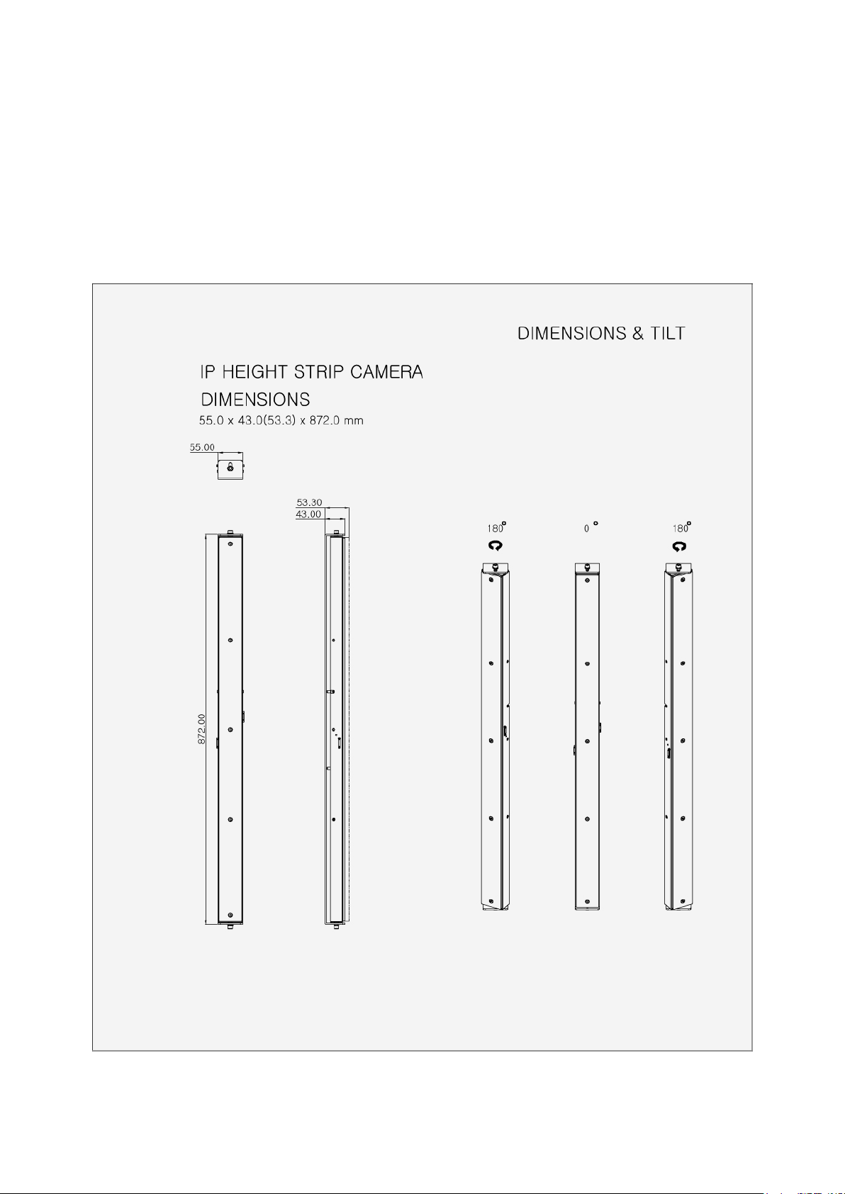
Camera Dimension
See the diagrams below for the exact dimension of the network camera.
8

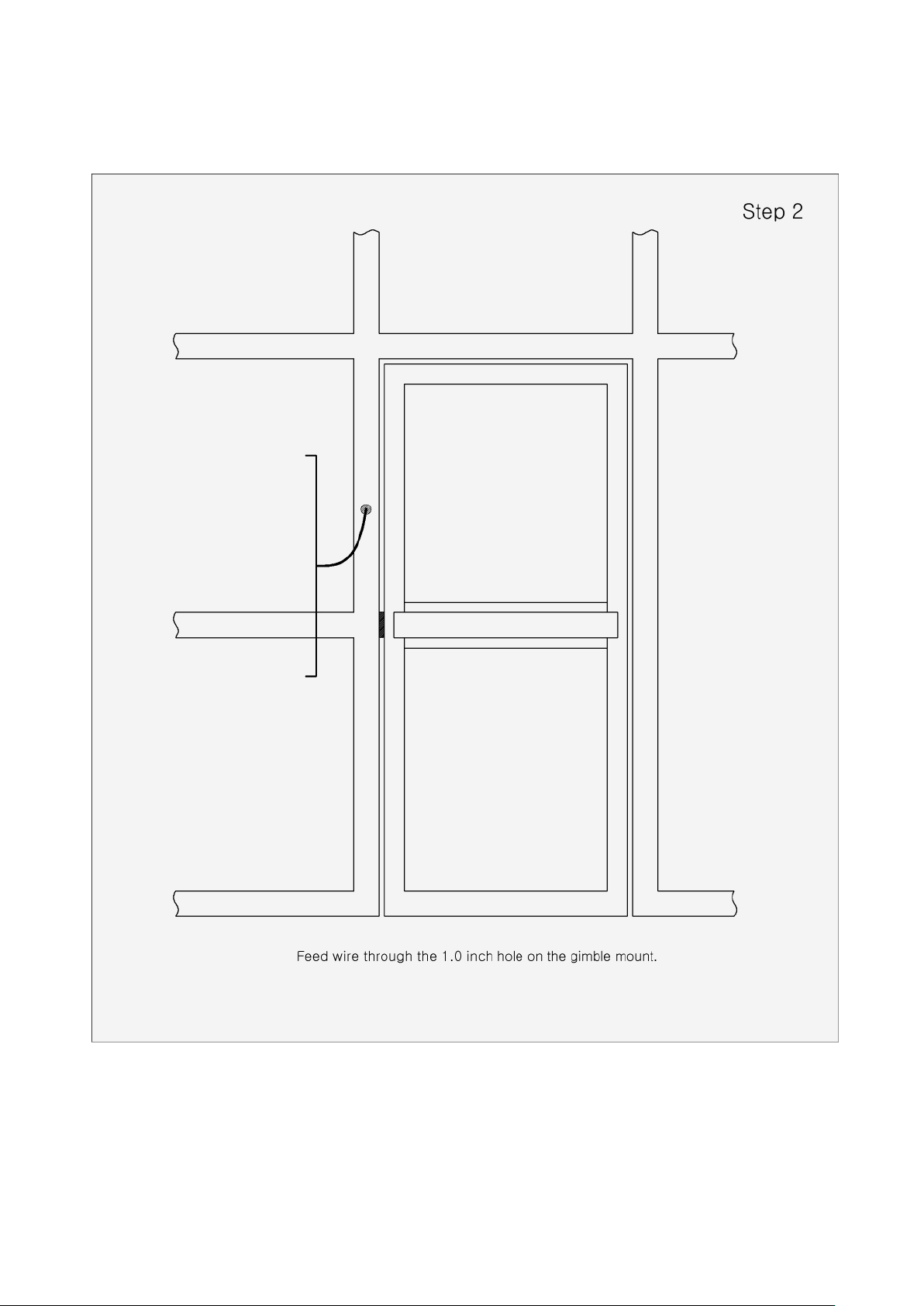
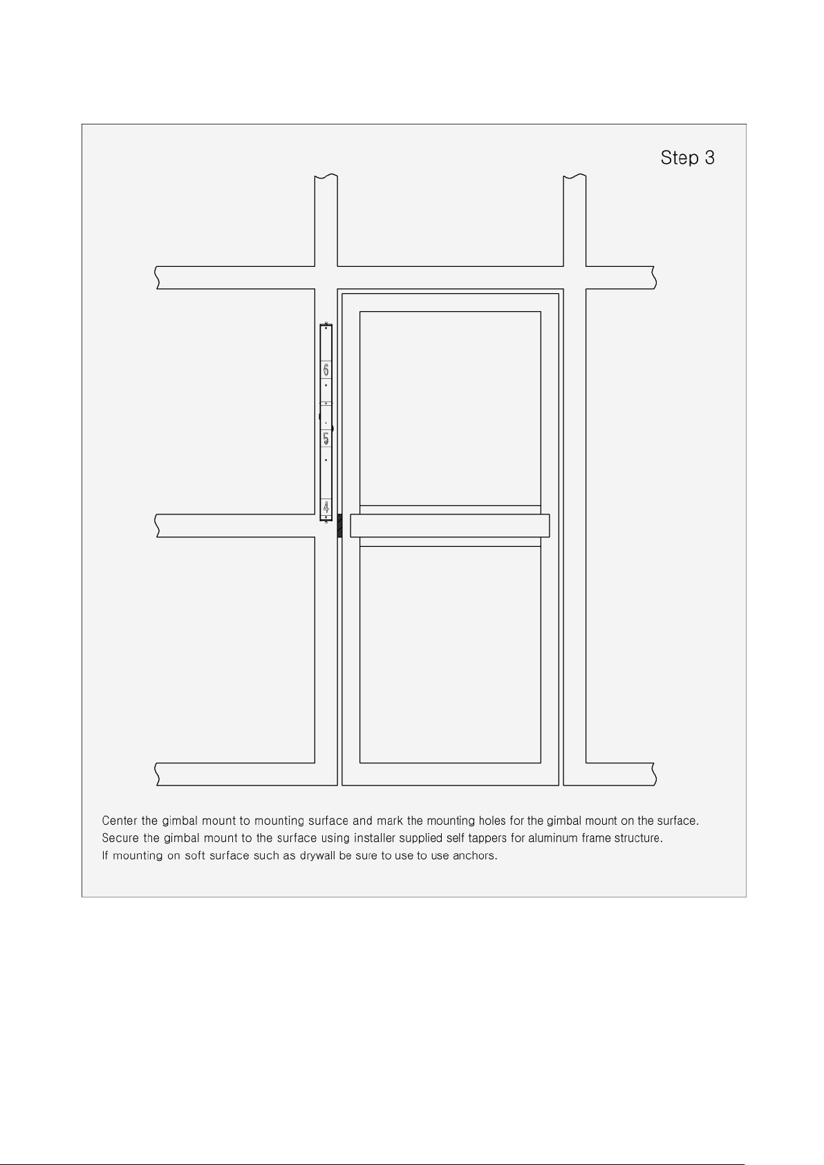
•
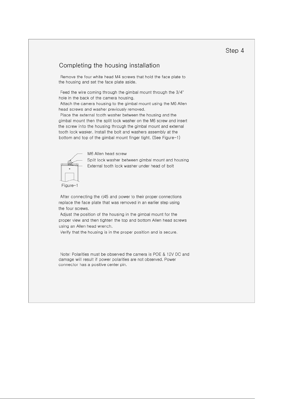
Installing Camera
9
10
11
12

13

2.2 CONNECTIONS
• Connecting the Network
Connect a standard RJ-45 cable to the network port of the camera. Generally a crossover
cable is used for directly connection to PC, while a direct cable is used for connection to a
hub.
• Connecting the BNC
Connect BNC cable for composite video output.
• Connecting the Power
Connect power of 12VDC for the camera.
When using a 12VDC adapter, connect the positive (+) pole to the ‘+’ position and the
negative
(-) pole to the ‘-’ position.
Use satisfy clause 2.5 of IEC60950-1/UL60950-1 or Certified/Listed Class 2 power source
only.
– Be careful not to reverse the polarity when you connect the power cable.
14
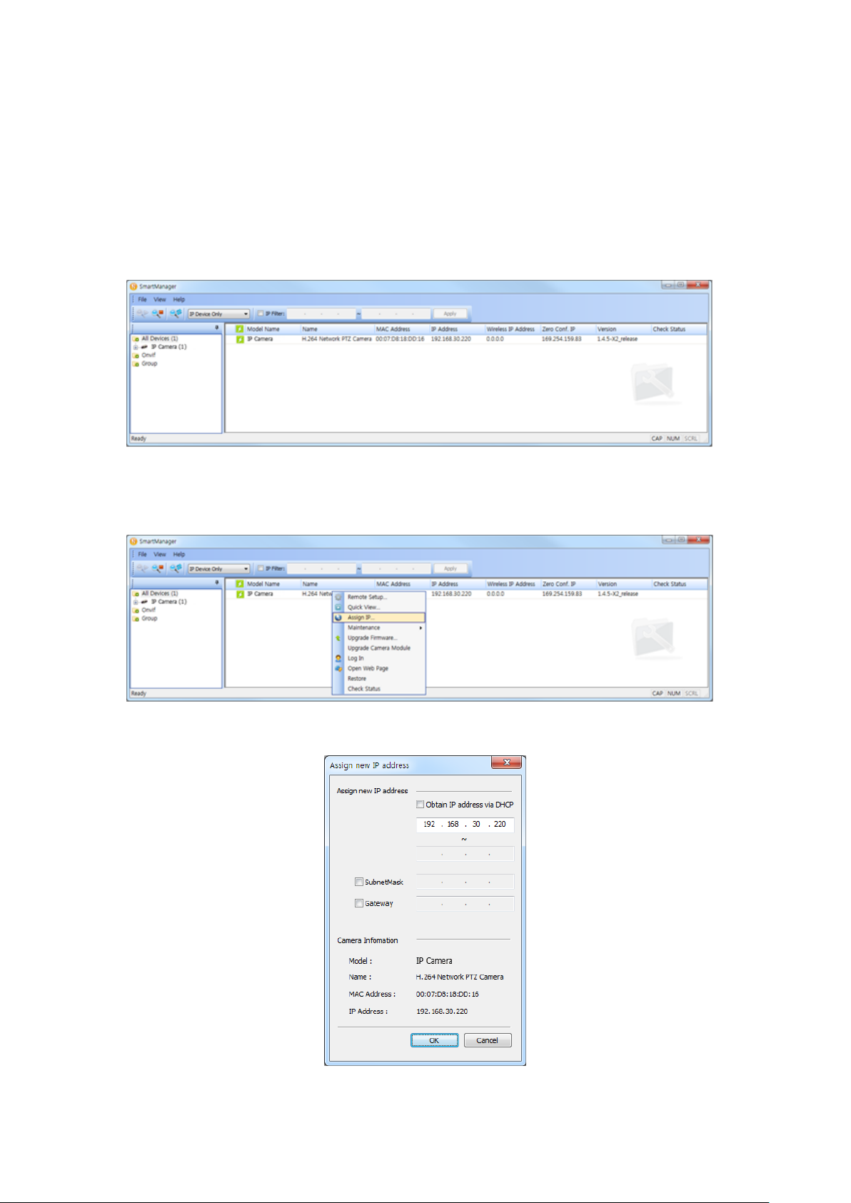
2.3 NETWORK CONNECTION & IP ASSIGNMENT
The network camera supports the operation through the network. When a camera is first
connected to the network, it is necessary to allocate an IP address to the device with the
SmartManager utility on the CD. (Default IP 192.168.30.220)
1) Connect the network camera/device to the network and power up.
2) Start SmartManager utility (Start > All programs > SmartManager > SmartManager).
The main window will display, and after a short while any network devices connected to the
network will be displayed in the list.
3) Select the camera on the list and click right button of the mouse. You can see the pop-up menu
as below.
4) Select Assign IP Address. The Assign IP window will display. Enter the required IP address.
NOTE: For more information, refer to the SmartManager User’s Manual.
15
3 Operation
The network camera can be used with Windows operating system and browsers. The
recommended browsers are Internet Explorer, Safari, Firefoxand Opera with Windows.
NOTE: To view streaming video in Microsoft Internet Explorer, set your browser to allow ActiveX
controls.
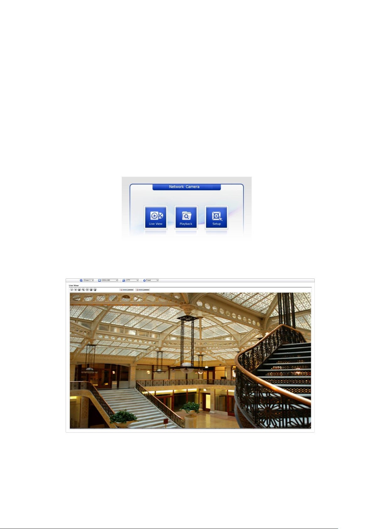
3.1 ACCESS FROM A BROWSER
1. Start a browser (Internet Explorer).
2. Enter the IP address or host name of the network camera in the Location/Address field of your
browser.
3. You can see a starting page. Click Live View, Playback, or Setup to enter web page.
4. The network cameras Live View page appears in your browser.
16
3.2 Access from the internet
Once connected, the network camera is accessible on your local network (LAN). To access the
network camera from the Internet you must configure your broadband router to allow incoming data
traffic to the network camera. To do this, enable the NAT traversal feature, which will attempt to
automatically configure the router to allow access to the network camera. This is enabled from
Setup > System > Network > NAT. For more information, please see “System > Network > NAT” of
User’s Manual.
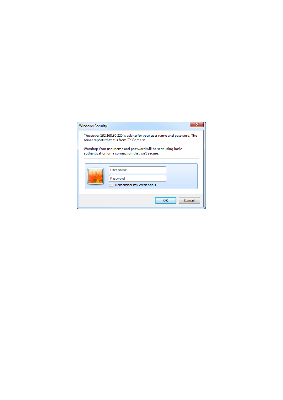
3.3 Setting the admin password over a secure connection
To gain access to the product, the password for the default administrator user must be set. This is
done in the Admin Password dialog, which is displayed when the network camera is accessed for
the setup at the first time. Enter your admin name and password, set by the administrator.
NOTE: The default administrator user name and password is admin. If the password is lost, the
network camera must be reset to the factory default settings. Please see Resetting to the
factory default settings.
To prevent network eavesdropping when setting the admin password, this can be done via an
encrypted HTTPS connection, which requires an HTTPS certificate (see NOTE below). To set the
password via a standard HTTP connection, enter it directly in the first dialog shown below. To set
the password via an encrypted HTTPS connection, please see “System > Security > HTTPS” of
User’s Manual.
NOTE: HTTPS (Hypertext Transfer Protocol over SSL) is a protocol used to encrypt the traffic
between web browsers and servers. The HTTPS certificate controls the encrypted
exchange of information.
17
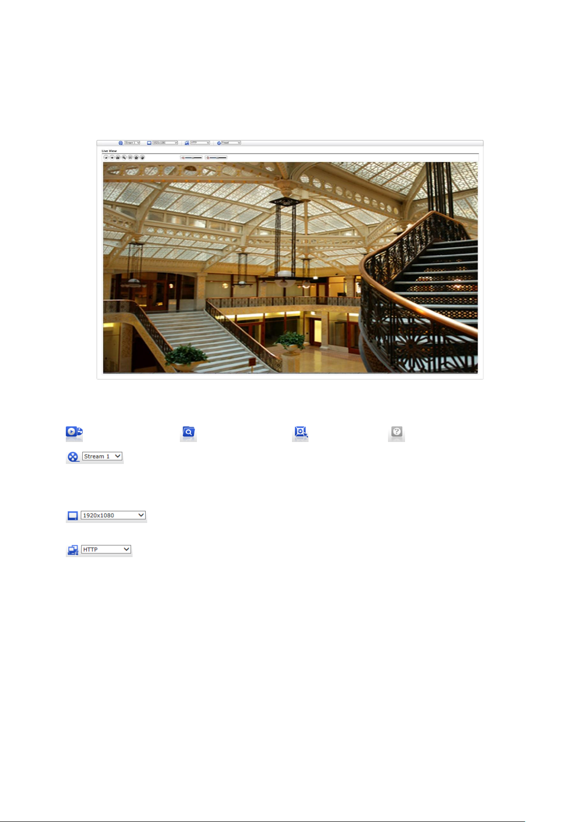
3.4 Live View Page
The Live View page comes in several screen modes: 1920x1080, 1280x1024, 1280x720(960),
1024x768, 704x480(576), 640x480(360) and 320x240. Users are allowed to select the most
suitable one out of those modes. Adjust the mode in accordance with your PC specifications and
monitoring purposes.
1) General controls
Live View Page Playback Page Setup Page Help Page
The video drop-down list allows you to select a customized or preprogrammed
video stream on the Live View page. Stream profiles are configured under Setup
> Basic Configuration > Video & Image. For more information, please see “Basic
Configuration > Video & Image” of User’s Manual.
The resolution drop-down list allows you to select the most suitable one out
of video resolutions to be displayed on Live View page.
The protocol drop-down list allows you to select which combination of protocols
and methods to use depending on your viewing requirements, and on the
properties of your network.
18

2) Control toolbar
The live viewer toolbar is available in the web browser page only. It displays the following
buttons:
The Stop button stops the video stream being played. Pressing the key again toggles the
play and stop.
The Play button connects to the network camera or starts playing a video stream.
The Pause button pauses the video stream being played.
The Snapshot button takes a snapshot of the current image. The location where the image
is saved can be specified.
The Digital Zoom button activates a zoom-in or zoom-out function for video image on the
live screen.
The Full Screen button causes the video image to fill the entire screen area. No other
windows will be visible. Press the ’Esc’ button on the computer keyboard to cancel full
screen view.
The Manual Trigger button activates a pop-up window to manually start or stop the event.
The VCA button shows/hides VCA rule setting and detected objects.
The Face Detector button shows/hides detected faces.
NOTE1: VCA and Face Detector buttons appear only when each function is activated.
NOTE2: VCA and Face Detector works exclusively to each other.
3) Video Streams
The network camera provides several images and video stream formats. Your requirements and
the properties of your network will determine the type you use.
The Live View page in the network camera provides access to H.264 and Motion JPEG video
streams, and to the list of available video streams. Other applications and clients can also
access these video streams/images directly, without going via the Live View page.
19
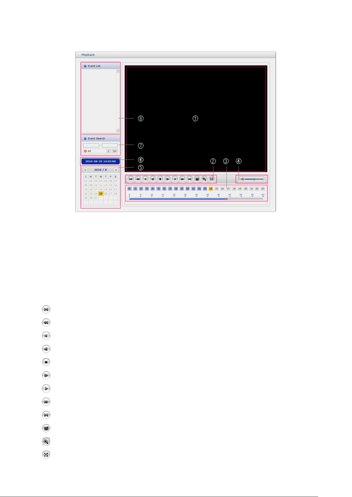
3.5 Playback
The Playback window contains a list of recordings made to the memory card. It shows each
recording’s start time, length, the event type used to start the recording, calendar and time slice bar
indicates if the recording is existed or not.
The description of playback window follows.
1) Video Screen
You can see the video screen when playing the video clip in the Micro SD memory.
2) Playback Buttons
To view a recording data in the SD local storage, select it from the list and click the Playback
buttons.
Go to the first: go to the beginning of the video clip.
Fast backward play: fast play backward of the video clip.
Backward play: play backward of the video clip.
Step backward play: go back one frame of the video clip.
Pause: pause playback of the video clip.
Step forward play: go forward one frame of the video clip.
Forward Play: play forward the video clip.
Fast forward play: play fast forward of the video clip.
Go to the last: go to the end of the video clip.
Clip copy: copy the video clip.
Zoom In: zoom in the video clip.
Full Screen: display full screen of the video.
20
3) Time Chart
Display an hour-based search screen for the chosen date. If there is recording data, a blue
section will be displayed on a 24-hour basis. If you select a particular hour in the chart, a yellow
square on the hour will be displayed.
4) Speaker Control Bar
Use this scale to control the volume of the speakers.
5) Search Calendar
Search results from the SD local storage in the network camera connected are displayed
monthly. If there is a recorded data for a particular date, a blue square on the date will be
displayed. If you select a particular date in the calendar, a yellow square on the date will be
displayed.
6) Play Time
Displays time of the video playing.
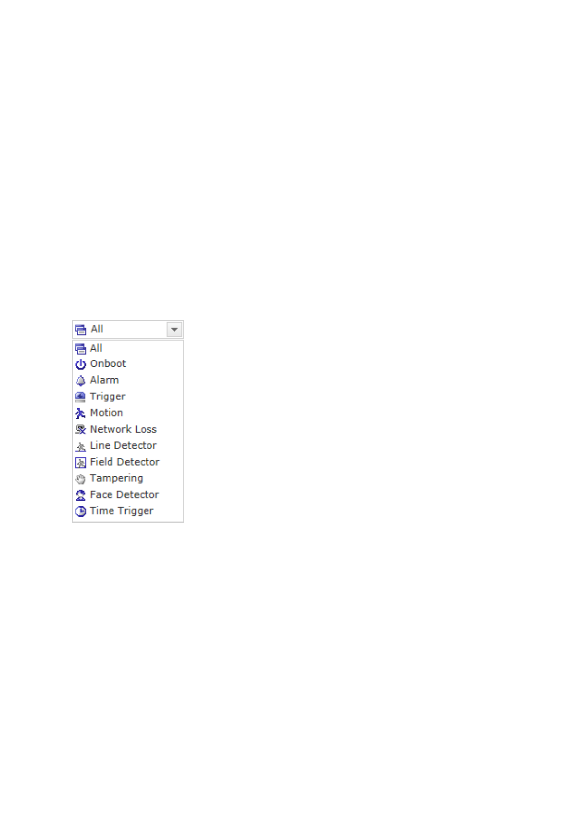
7) Event Search Window
Select a search option in the drop-down list and click GO button. You can also enter the time
period for searching. If you click Start Date or End Date zone, displays Search Calendar.
8) Event List Window
Event List displays the event(s) that were recorded in the SD local storage. Select a list and
click the play button. The video clip will be played.
21
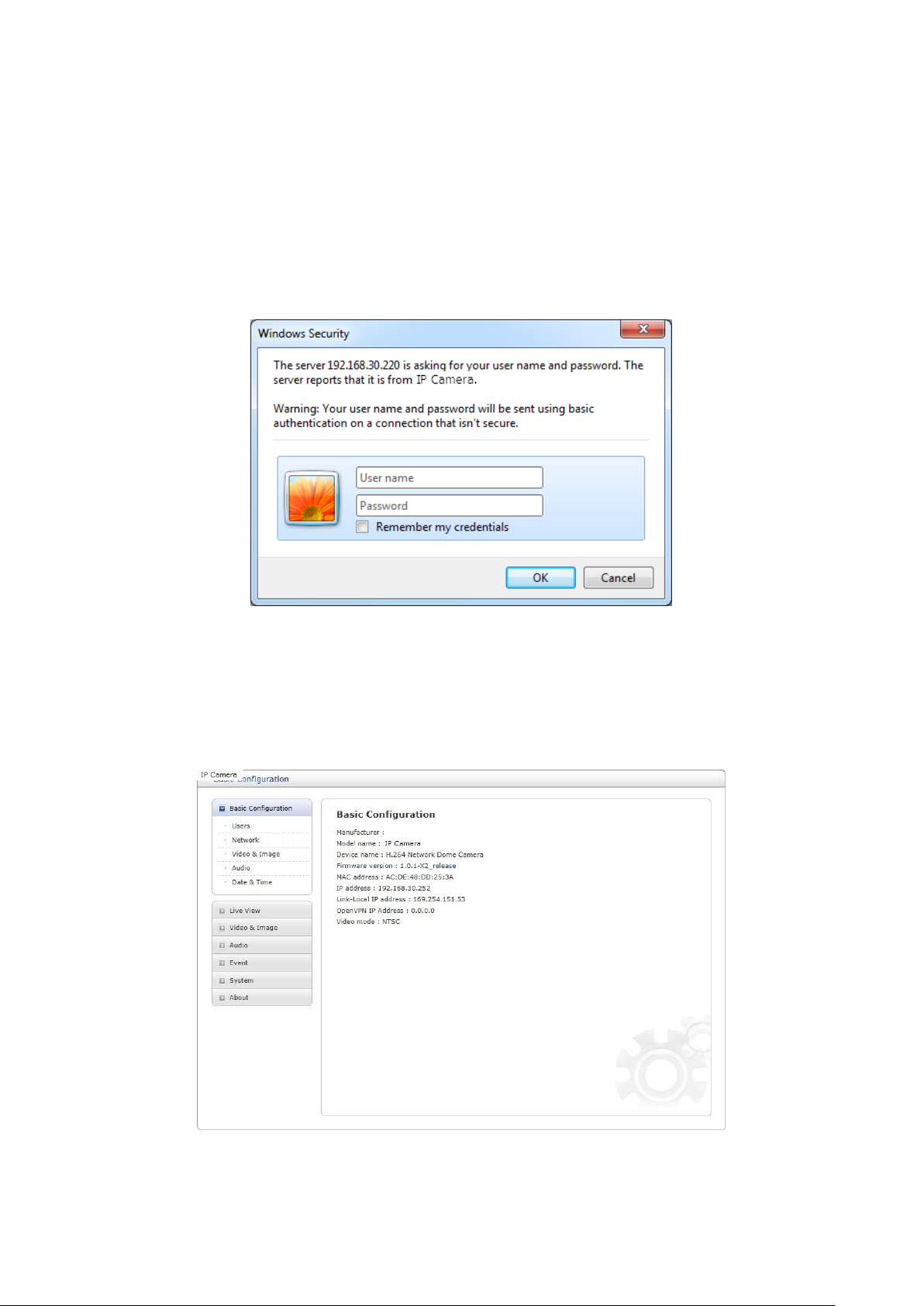
3.6 Network Camera Setup
This section describes how to configure the network camera.
Administrator has unrestricted access to all the Setup tools, whereas Operators have access to the
settings of Basic Configuration, which are Live View, Video & Image, Audio, Event, Dome
Configuration, and System.
You can configure the network camera by clicking Setup either in the first connection page or the
top second-right button of the Live View page. Accessing the network camera from a computer for
the first time opens the Admin Password dialog box. Enter your administrator or operator id and
password to get into setup page.
NOTE: If the password is lost, the network camera must be reset to the factory default settings.
Please see “Resetting to the Factory Default Setting”.
3.6.1
Basic Configuration
You can see the device information in this information page.
22
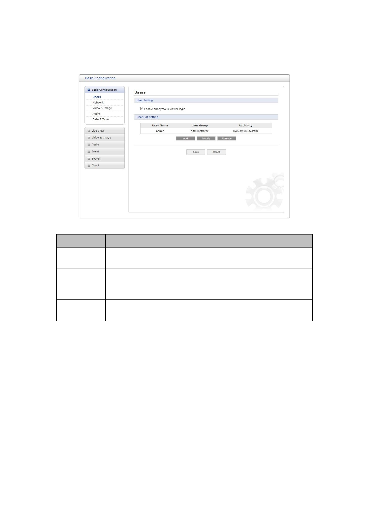
User Group
Authority
Guest
Provides the lowest level of access, which only allows access to
the Live View page.
Operator
An operator can view the Live View page, create and modify
events, and adjust certain other settings. Operators have no
access to System Options.
Administrator
An administrator has unrestricted access to the Setup tools and
can determine the registration of all other users.
1) Users
User access control is enabled by default. The administrator can set up other users, by giving user
names and passwords. It is also possible to allow anonymous viewer login, which means that
anybody may access the Live View page, as described below:
The user list displays the authorized users and user groups (levels):
• Enable anonymous viewer login: Check the box to use the webcasting features. Refer to
“Video & Image > Webcasting” for more details.
Please refer to “System > Security > Users” for more details about User setup.
23
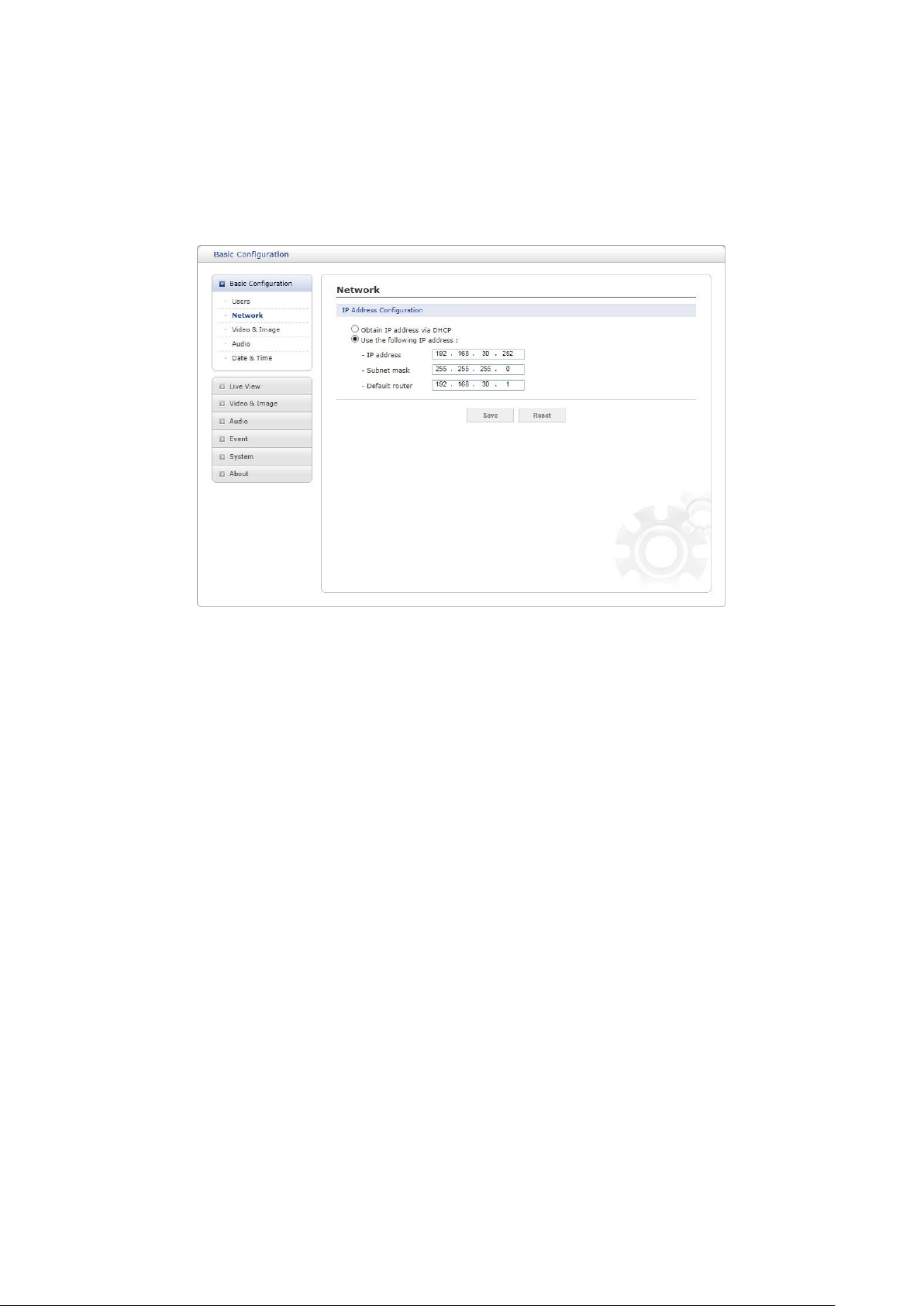
2) Network
The network camera supports both IP version 4 and IP version 6. Both versions may be enabled
simultaneously, and at least one version must always be enabled. When using IPv4, the IP
address for the network camera can be set automatically via DHCP, or a static IP address can be
set manually. If IPv6 is enabled, the network camera receives an IP address according to the
configuration in the network router. There is also an option of using the Internet Dynamic DNS
Service. For more information on setting the network, please see “System > Network > Basic”.
• Obtain IP address via DHCP: Dynamic Host Configuration Protocol (DHCP) is a protocol that
lets network administrators centrally manage and automate the assignment of IP addresses on a
network. DHCP is enabled by default. Although a DHCP server is mostly used to set an IP
address dynamically, it is also possible to use it to set a static, known IP address for a particular
MAC address.
• Use the following IP address: To use a static IP address for the network camera, check the
radio button and then make the following settings:
– IP address: Specify a unique IP address for your network camera.
– Subnet mask: Specify the mask for the subnet the network camera is located on.
– Default router: Specify the IP address of the default router (gateway) used for connecting
devices attached to different networks and network segments.
NOTES:
1. DHCP should only be enabled if using dynamic IP address notification, or if your DHCP server
can update a DNS server, which then allows you to access the network camera by name (host
name). If DHCP is enabled and you cannot access the unit, you may have to reset it to the
factory default settings and then perform the installation again.
2. The ARP/Ping service is automatically disabled two minutes after the unit is started, or as
soon as an IP address is set.
3. Pinging the unit is still possible when this service is disabled.
Please refer to “System > Network > Basic” for more details about Network setup.
24
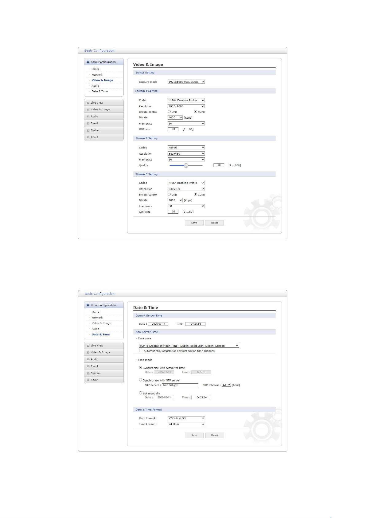
3) Video & Image
User can setup and change setting of individual video stream in this page.
Please refer to “Video & Image > Basic” for more details about Video & Image setup.
4) Date & Time
User can set time directly or assign time server to get the current time, as well as determine Date &
Time format in this page.
Please refer to “System > Date & Time” for more details about Date & Time setup.
25
 Loading...