

Page 1
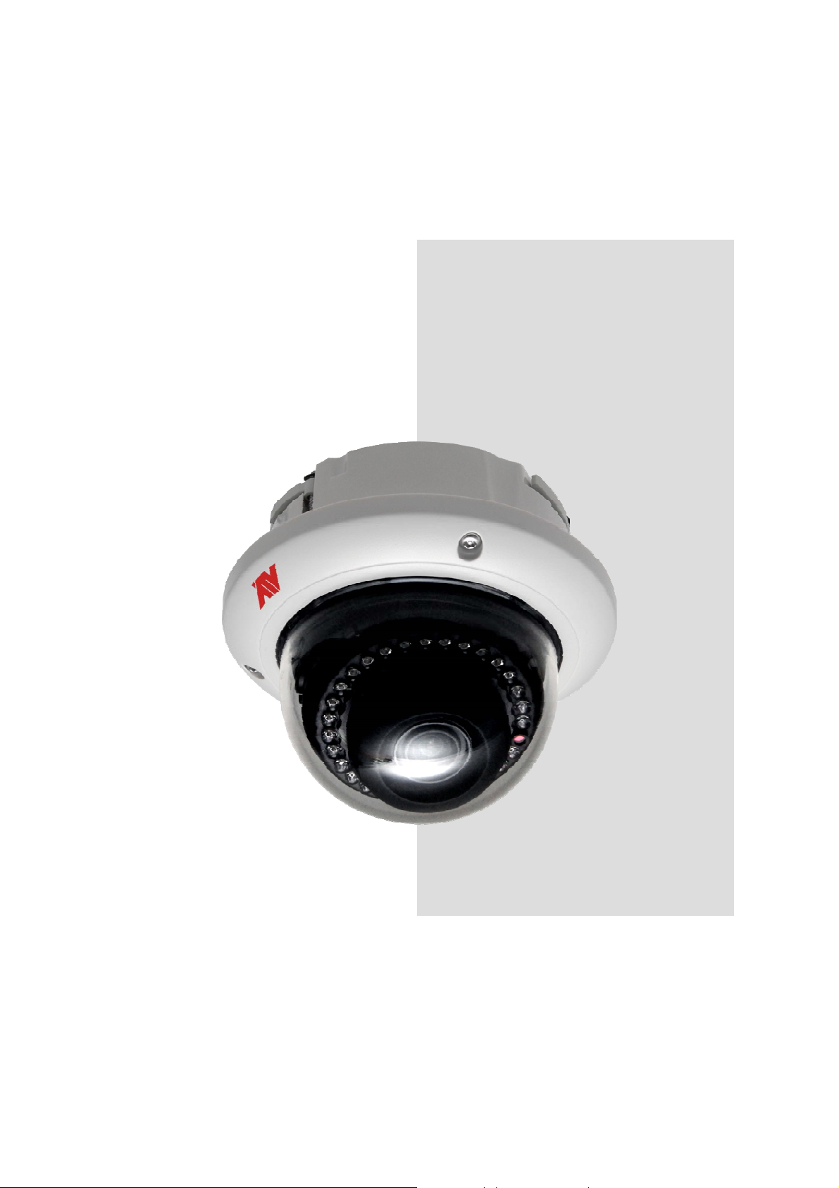
INSTRUCTION MANUAL
IR Interior/
Exterior Dome
Network Camera IPFD2TI
Please read this manual thoroughly before use, and ke ep it handy for future reference.
Page 2
WARNING
TO REDUCE THE RISK OF FIRE OR ELECTRIC SHOCK, DO NOT EXPOSE THIS
PROCUCT TO RAIN OR MOISTURE. DO NOT INSERT ANY METALLIC OBJECT
THROUGH THE VENTILATION GRILLS OR OTHER OPENNINGS ON THE
EQUIPMENT.
Apparatus shall not be exposed to dripping or splashing and that no objects filled
with liquids, such as vases, shall be placed on the apparatus.
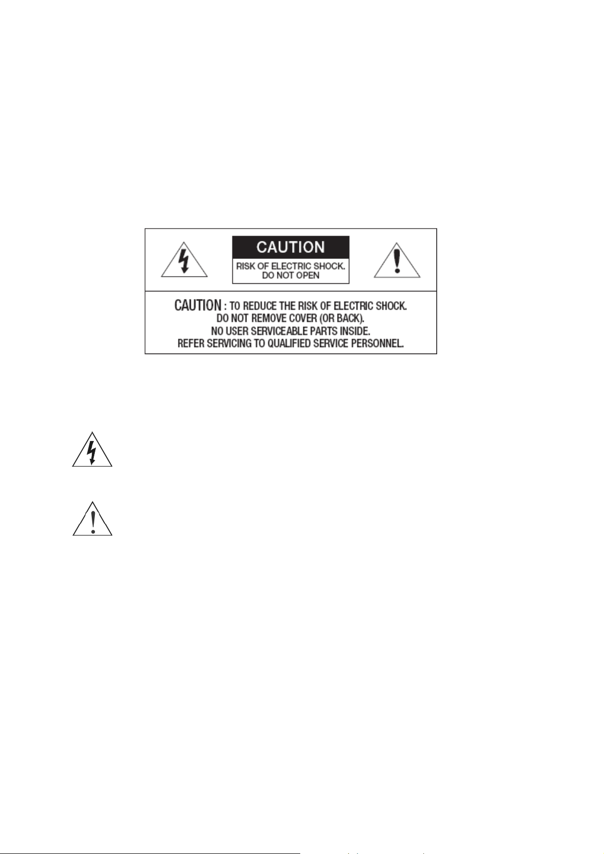
CAUTION
EXPLANATION OF GRAPHICAL SYMBOLS
The lightning flash with arrowhead symbol, within an equilateral triangle, is
intended to alert the user to the presence of uninsulated "dangerous
voltage" within the product’s enclosure that may be of sufficient magnitude
to constitute a risk of electric shock.
The exclamation point within an equilateral triangle is intended to alert the
user to the presence of important operating and maintenance (servicing)
instructions in the literature accompanying the appliance.
2
Page 3

FCC COMPLIANCE STATEMENT
This device complies with Part 15 of the FCC Rules. Operation is subject to the following two
conditions : (1) this device may not cause harmful interference, and (2) this device must accept any
interference received, including interference that may cause undesired operation.
INFORMATION TO THE USER: THIS EQUIPMENT HAS BEEN TESTED AND FOUND TO
COMPLY WITH THE LIMITS FOR A CLASS A DIGITAL DEVICE, PURSUANT TO PART 15 OF THE FCC
RULES. THESE LIMITS ARE DESIGNED TO PROVIDE REASONABLE PROTECTION AGAINST HARMFUL
INTERFERENCE WHEN THE EQUIPMENT IS OPERATED IN A COMMERCIAL ENVIRONMENT. THIS
EQUIPMENT GENERATES, USES, AND CAN RADIATE RADIO FREQUENCY ENERGY AND IF NOT
INSTALLED AND USED IN ACCORDANCE WITH THE INSTRUCTION MANUAL, MAY CAUSE HARMFUL
INTERFERENCE TO RADIO COMMUNICATIONS.
CAUTION: CHANGES OR MODIFICATIONS NOT EXPRESSLY APPROVED BY THE PARTY
RESPONSIBLE FOR COMPLIANCE COULD VOID THE USER'S AUTHORITY TO OPERATE THE
EQUIPMENT.
THIS CLASS A DIGITAL APPARATUS COMPLIES WITH CANADIAN ICES-003.
CET APPAREIL NUMÉRIQUE DE LA CLASSE A EST CONFORME À LA NORME NMB-003 DU CANADA.
CE COMPLIANCE STATEMENT
WARNING: This is a Class A product. In a domestic environment this product may cause radio
interference in which case the user may be required to take adequate measures.
RISK OF EXPLOSION IF BATTERY IS REPLACED BY AN INCORRECT TYPE.
CAUTION
DISPOSE OF USED BA TTERIES ACCORDING TO THE INSTRUCTIONS
3
Page 4

IMPORTANT SAFETY INSTRUCTIONS
1. Read these instructions.
2. Keep these instructions.
3. Heed all warnings.
4. Follow all instructions.
5. Do not use this apparatus near water.
6. Clean only with dry cloth.
7. Do not block any ventilation openings. Install in accordance with the manufacturer’s
instructions.
8. Do not install near any heat sources such as radiators, heat registers, stoves, or other
apparatus (including amplifiers) that produce heat.
9. Do not defeat the safety purpose of the polarized or grounding-type plug. A polarized plug
has two blades with one wider than the other. A grounding type plug has two blades and a
third grounding prong. The wide blade or the third prong is provided for your safety. If the
provided plug does not fit into your outlet, consult an electrician for replacement of the
obsolete outlet.
10. Protect the power cord from being walked on or pinched particularly at plugs, convenience
receptacles, and the point where they exit from the apparatus.
11. Only use attachments/accessories specified by the manufacturer.
12. Use only with the cart, stand, tripod, bracket, or table specified
by the manufacturer, or sold with the apparatus. When a cart is
used, use caution when moving the cart/apparatus combination
to avoid injury from tip-over.
13. Unplug this apparatus during lightning storms or when unused
for long periods of time.
14. Refer all servicing to qualified service personnel. Servicing is
required when the apparatus has been damaged in any way,
such as power-supply cord or plug is damaged, liquid has been
spilled or objects have fallen into the apparatus, the apparatus has been exposed to rain or
moisture, does not operate normally, or has been dropped.
15. CAUTION – THESE SERVICING INSTRUCTIONS ARE FOR USE B Y QUALIFIED
SERVICE PERSONNEL ONLY. TO REDUCE T HE RISK OF ELECTRIC SHOCK DO
NOT PERFORM ANY SERVICING OTHER THAN THAT CONTAINED IN THE
OPERATING INSTRUCTIONS UNLESS YOU QRE QUALIFIED TO DO SO.
16. Use power source that satisfies clause 2.5 of IEC60950-1/UL60950-1 or
Certified/Listed Class 2.
ITE is to be connected only to PoE networks without routing to the outside plant.
17.
4
Page 5

Contents
1. Description ------------------------------------------------------------------6
1.1 Components ---------------------------------------------------------------------------------------------6
1.2 Key Features ---------------------------------------------------------------------------------------------7
1.3 Layout ------------------------------------------------------------------------------------------------8
2. Installation ------------------------------------------------------------------ 9
2.1 Camera Installation -------------------------------------------------------------------------------------9
2.2 Network Connection and IP Assignment ---------------------------------------------------------- 14
3. Operation -------------------------------------------------------------------- 15
3.1 Access from a browser--------------------------------------------------------------------------------15
3.2 Access from the internet------------------------------------------------------------------------------ 16
3.3 Setting the admin password over a secure connection------------------------------------------- 16
3.4 Live View Page ----------------------------------------------------------------------------------------- 17
3.5 Network Camer a Setup--------------------------------------------------------------------------------19
3.5.1 Basic Configuration ----------------------------------------------------------------------------19
1) Users------------------------------------------------------------------------------------------ 20
2) Network --------------------------------------------------------------------------------------20
3) Video & Image ------------------------------------------------------------------------------ 22
4) Date & Time --------------------------------------------------------------------------------- 24
3.5.2 Live View ---------------------------------------------------------------------------------------25
3.5.3 Video & Image---------------------------------------------------------------------------------- 26
3.5.4 Event ------------------------------------------------------------------------------------------ 32
1) Event-In --------------------------------------------------------------------------------------32
1) Event-Out ------------------------------------------------------------------------------------ 37
2) Event Map------------------------------------------------------------------------------------ 44
3.5.5 System ------------------------------------------------------------------------------------------ 45
1) Information ---------------------------------------------------------------------------------- 45
2) Security--------------------------------------------------------------------------------------- 46
3) Date & Time ---------------------------------------------------------------------------------49
4) Network -------------------------------------------------------------------------------------- 50
5) Language------------------------------------------------------------------------------------- 60
6) Maintenance--------------------------------------------------------------------------------- 60
7) Support--------------------------------------------------------------------------------------- 61
3.5.6 About--------------------------------------------------------------------------------------------- 64
3.6 Playback-------------------------------------------------------------------------------------------------- 64
3.7 Help ------------------------------------------------------------------------------------------------------- 66
3.8 Resetting to the factory default settings -------------------------------------------------------------67
4. Appendix -------------------------------------------------------------------- 68
4.1 Troubleshooting -----------------------------------------------------------------------------------------68
4.2 Preventive Maintenance -------------------------------------------------------------------------------- 69
4.3 Product Specification------------------------------------------------------------------------------------ 70
5
Page 6
1. Description
This manual applies to the IPFD2TI network camera.
The Network Camera supports the network service f or a sensor image with progressive scan, which
can be monitored on a real-time screen regardless of distances and locations. By using its dedicated
program, many users are able to ha ve an access to the Network Camera at once or a single user can
monitor various network camera s at the same time. It also enables users to play, store and retrieve a
monitoring image by using a PC. All the settings and real-time monitoring screens are also provided
through an access to the web.
The Network Camera is fully featured f or security surveillance and remote monitoring needs. It is
based on the DSP compression chip, and makes it available on the network as real-time, full frame
rate Motion JPEG and H.264 (or MPEG-4) video streams.
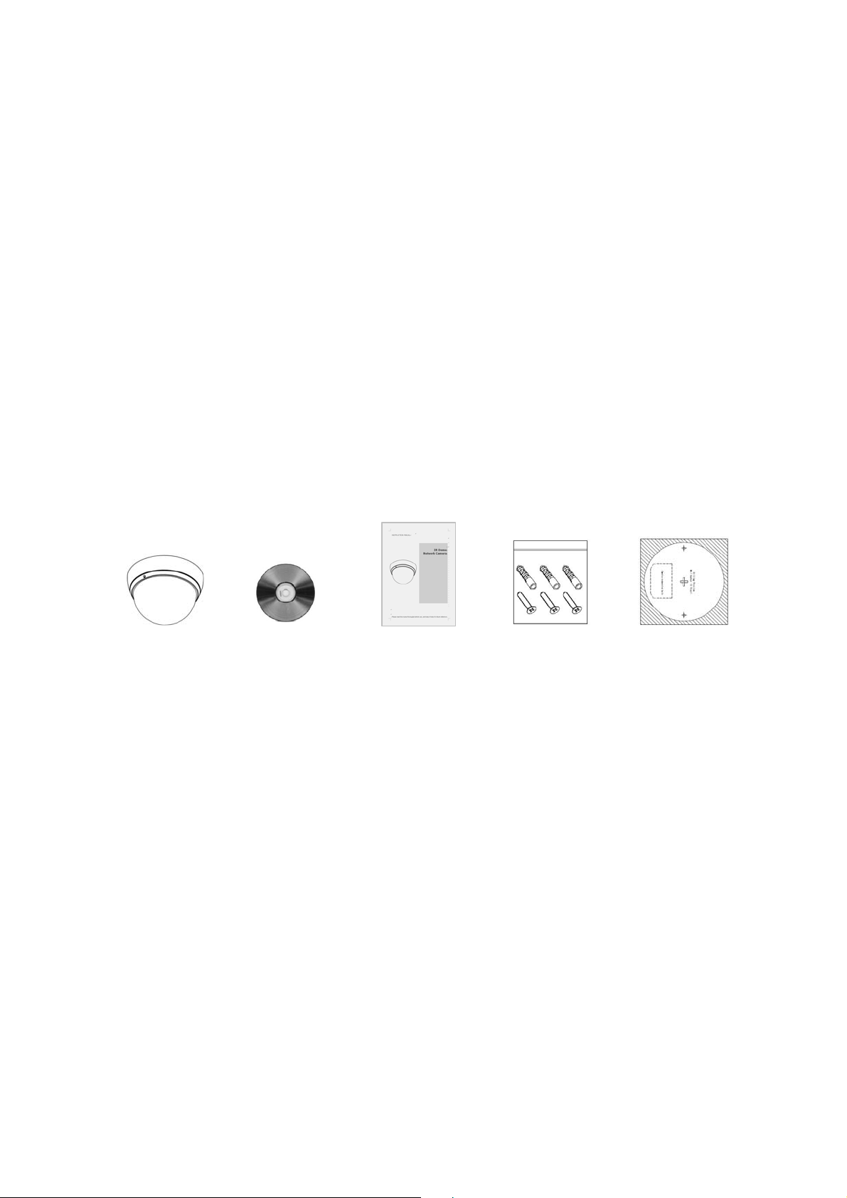
1.1 Components
The system comes with the following components:
Mini Camera Installation CD Installation Guide Accessory Kit Template sheet
Notes:
1. Check your package to make sure that you received the complete system, including all
components shown above.
2. Adapter for DC 12V is not supplied.
6
Page 7

1.2 Key Features
• Brilliant video quality
The Network Camera offers the highly efficient H.264 video compression, which drastically
reduces bandwidth and storage requirements without compromising image quality. Motion JPEG
is also supported for increased flexibility.
• Triple streams
The Network Camera can deliver triple video streams simultaneously at full frame rate in all
resolutions up to 1920 x 1080 using Motion JPEG and H.264 (or MPEG-4). This mean s that
several video streams can be configured with different compression formats, resolutions and
frame rates for dif ferent needs.
• Image setting adjustment
The Network Camera also enables users to adjust image settings such as contrast, brightne ss
and saturation to improve images before encoding takes place.
• Micro-SD Recording support
The Network Camera also supports a micro-SD memory slot for loc al recording with removable
storage.
• Improved Security
The Network Camera logs all user access, and lists currently connected users. Also, its full frame
rate video can be provided over HTTPS.
• Megapixel Resolution
Max 30fps@1920x1080
• PoE
This network camera can be powered through PoE, which simplifies installation since only one
cable is needed for carrying power, as well as video controls.
• ONVIF
This is a global interface standard that makes it easier for end users, in tegrators, consultants,
and manufacturers to take advantage of the possibilities offered by network video technology.
ONVIF enables interoperability between different vendor products, increased flexibility, reduced
cost, and future-proof systems.
7
Page 8

1.3 Layout
NO Name Description
1 Lens Allows wide area to be monitored
2 Ethernet Cable
3 Power Cable
Camera Dimension
See the diagrams below for the exact dimension
Cable for Ethernet (POE)
Cable for Power source (DC 12V)
8
Page 9
2. Installation
2.1 Camera Installation
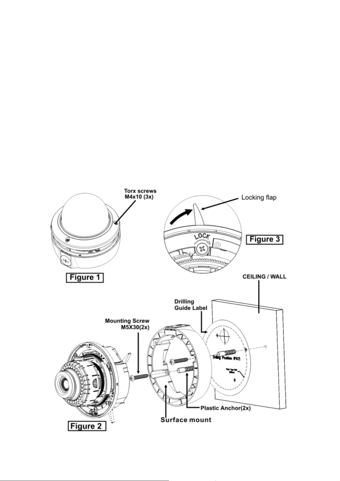
- Surface Type
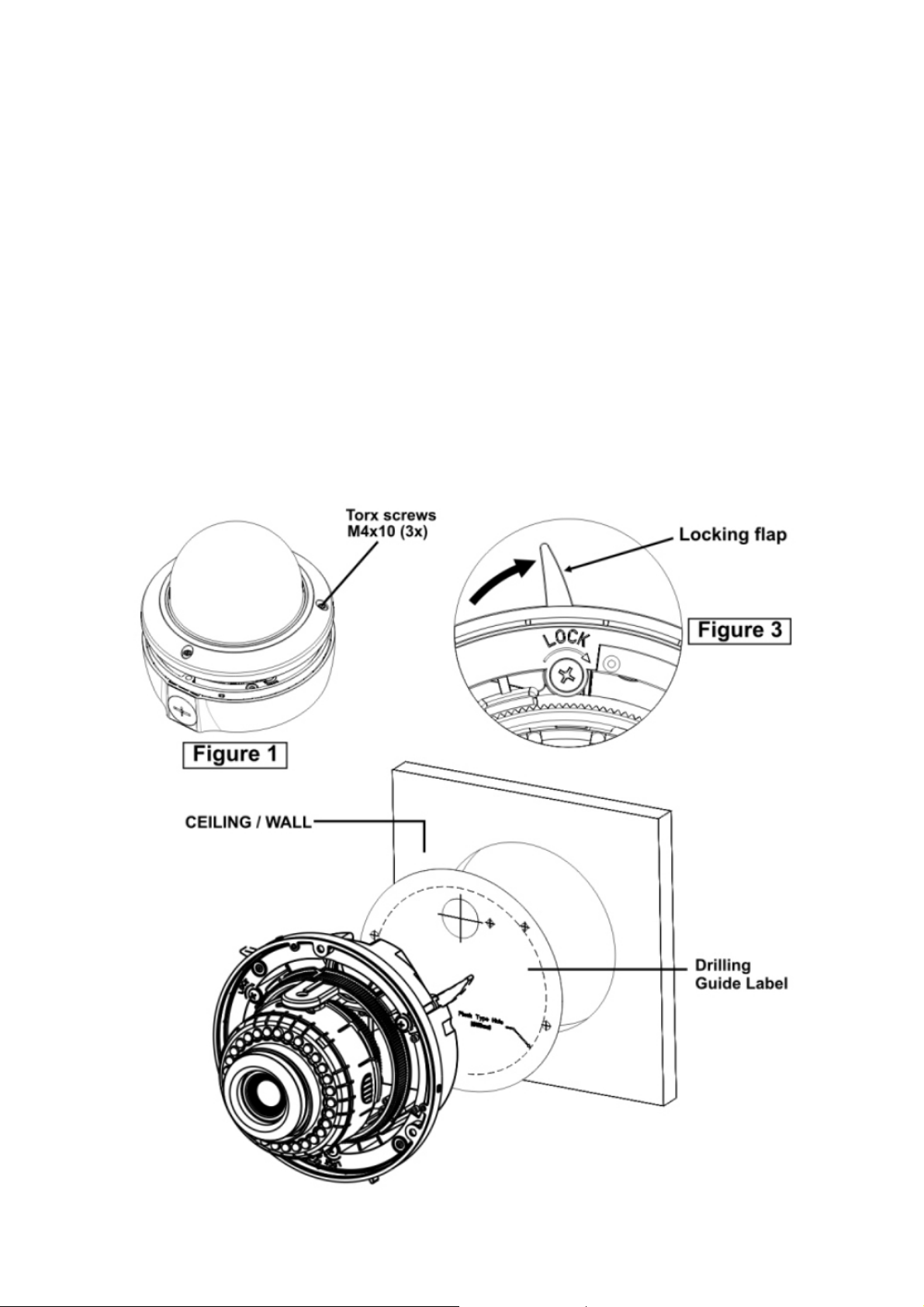
1. Loosen the three torx screws located midway up the front of the housing leave the screws intact in
the front portion (Fig. 1)
2. Drill the mounting location using the supplied drill guide label. (Fig. 2)
3. Attach the surface Mount the ceiling using suitable fasteners, M5x30 tapping screws are supplied
only use if they are suitable. (Fig. 2)
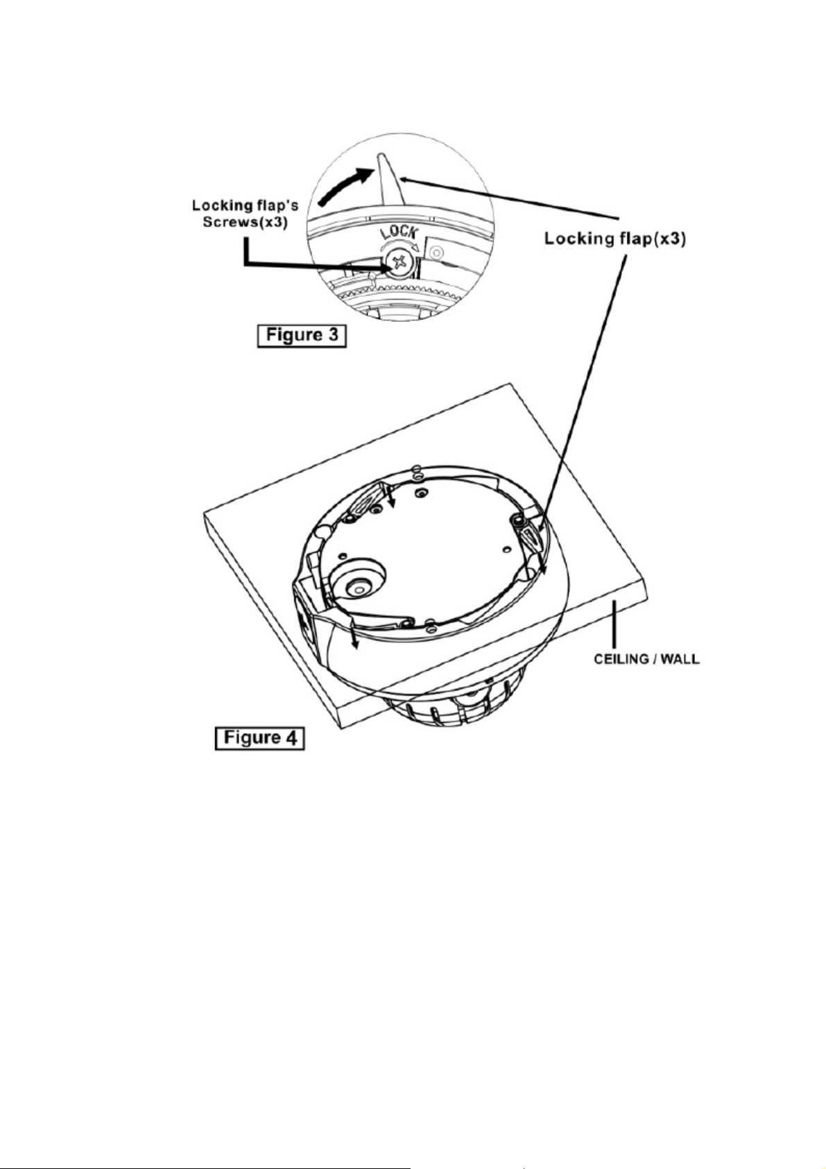
4. Insert the bottom case into the surface mount and turn the locking flap to fasten the bottom case
to the surface mount using 3 screws. (Fig.3)
5. Closing the housing using the loosen torx screws.
9
Page 10
10
Page 11
- Flush Type
Note: The ceiling tile cannot be thinner than 0.15inch (37mm)
1. Loosen the three torx screws located midway up the front of the housing leave the screws intact in
the front portion (Fig. 1)
2. Remove the ceiling tile from the ceiling. Draw a circle whose diameter is 116mm on the tile (You
can user carton with a hole). Cut the circle out of the ceiling tile. (Fig. 2)
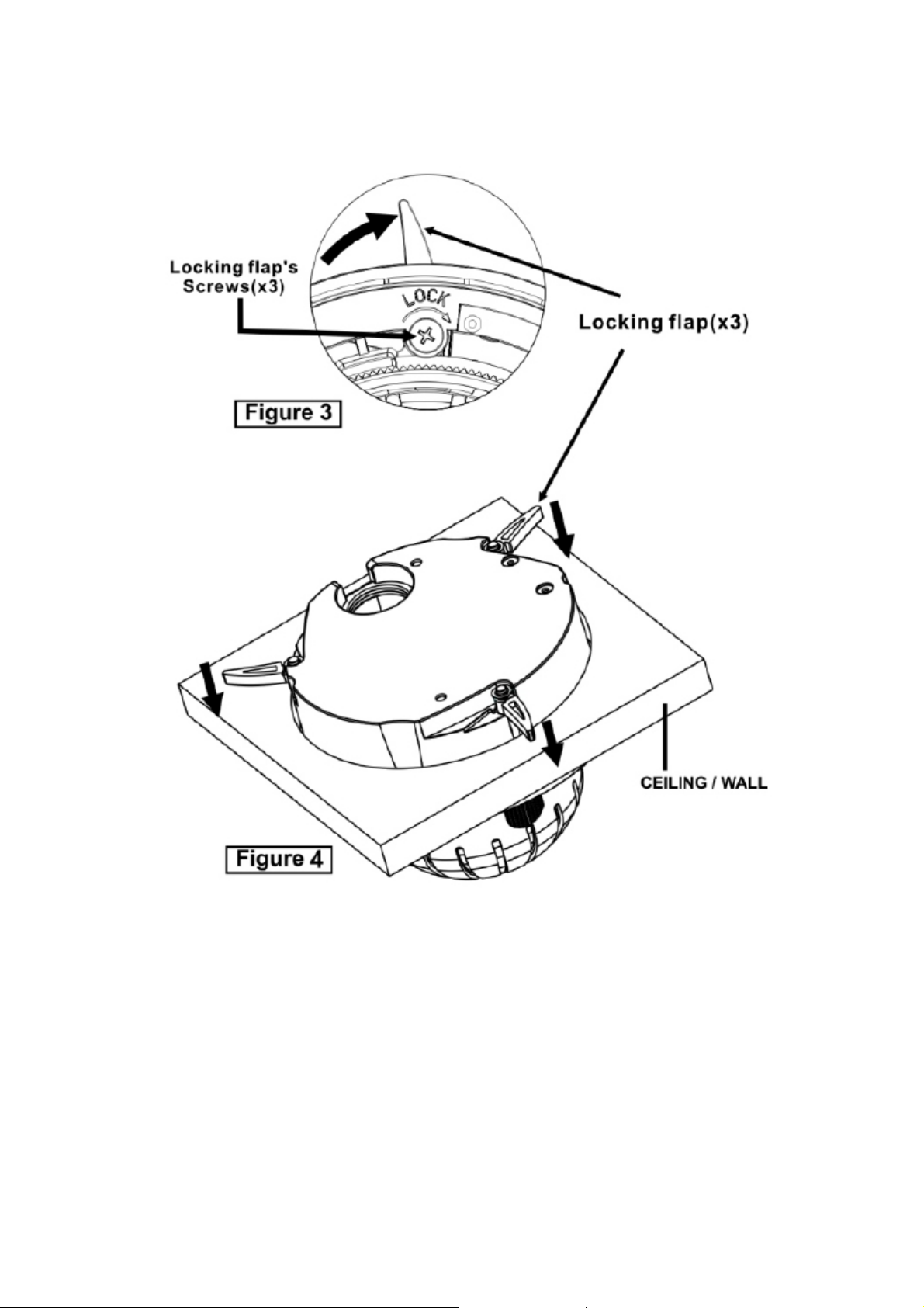
3. Insert the bottom case into the ceiling and turn the locking flap to fasten the bottom case to the
ceiling using 3 screws. (Fig. 3)
Note: when installing the camera flush with the ceiling,
three locking flaps hold firmly which makes it easy to install. (Fig. 4)
4. Closing the housing using the loosen torx screws
11
Page 12
12
Page 13
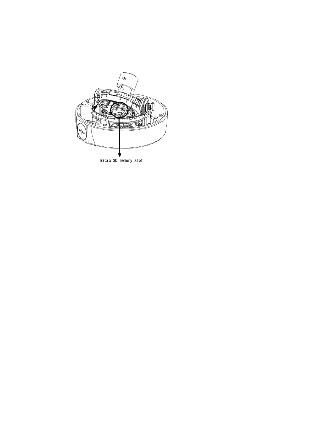
Micro SD memory slot
Insert the SD memory card.
• Connecting the Power
Connect 12VDC power source to the camera if not using PoE.
13
Page 14
2.2 Network Connection and IP assignment
The Network Camera supports the operation through the network. When a camera is first connected
to the network it has no IP address. So, it is necessary to allocate an IP address to the device with the
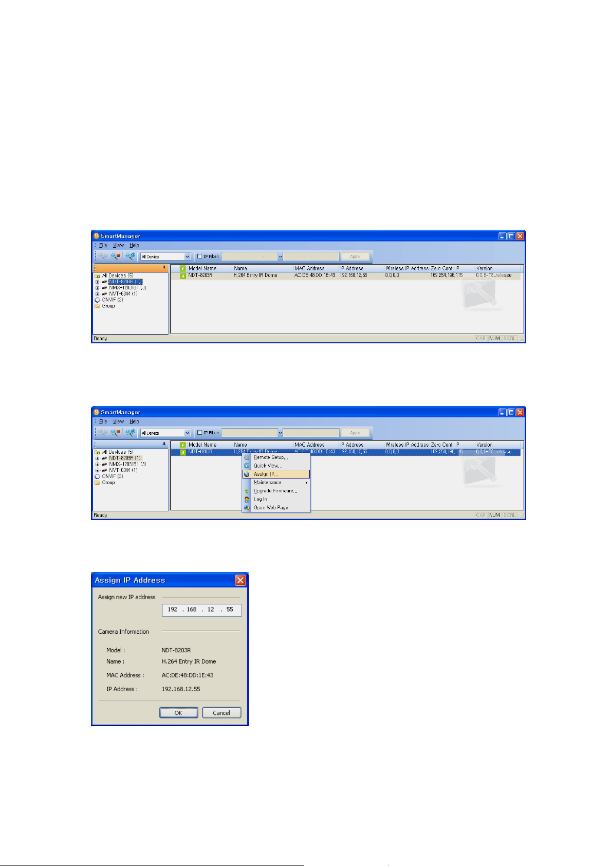
“Smart Manager” utility on the CD. (Default IP 192.168.30.220)
1. Connect the Network Camera / device to the network and power up.
2. Start SmartManager utility (Start>All programs>SmartManager>SmartManager), the main
window will be displayed, after a short while any network devices connected to the network will
be displayed in the list.
3. Select the camera on the list and click right button of the mouse. You can see the pop-up menu
below.
4. Select Assign IP. You can see an Assign IP window. Enter the required IP address.
Note: For more information, refer to the Smart Manger User’s Manual.
14
Page 15
3. Operation
The Network Camera can be used with Windows operating system and browsers. The recommended
browsers are Internet Explorer, Safari, Firefox, Opera and Google Chrome with Windows.
NOTE: To view streaming video in Microsoft Internet Explorer, set your browser to allow ActiveX
controls.
3.1 Access from a browser
1. Start a browser (Internet Explorer).
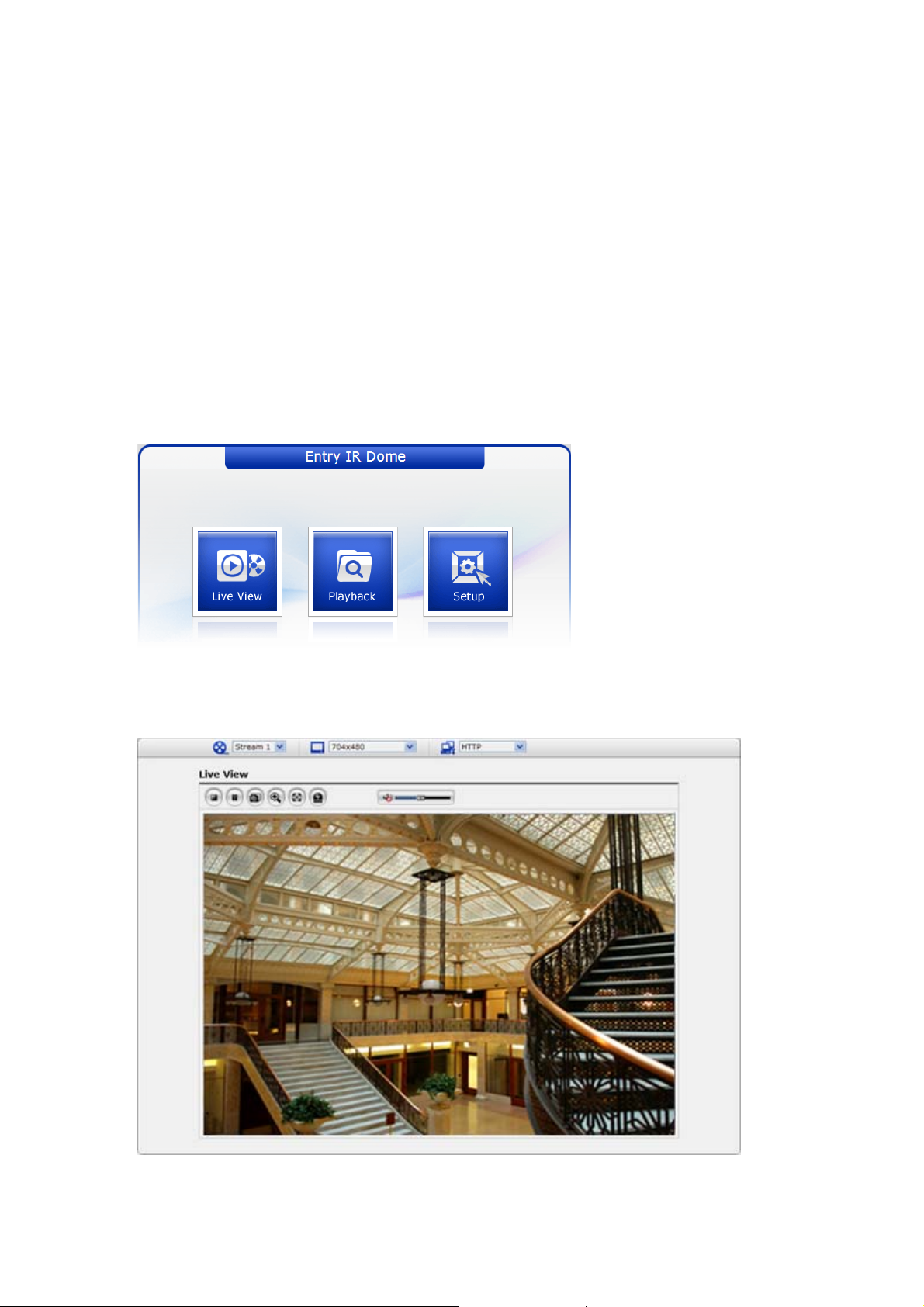
2. Enter the IP address or host name of the Network Camera in the Location/Addr ess field of your
browser.
3. You can see a starting page. Click Live View or Setup to enter web page.
4. The network camera’s Live View page appears in your browser.
15
Page 16
3.2. Access from the internet
To g
t
f
f
gs”
Access from the internet once connected, the Network Camera is accessible on your local network
(LAN). To access the network camera from the Internet you must configure your broadband router to
allow incoming data traffic to the network camera. To do this, enable the NAT-traversal feature, which
will attempt to automatically configure the router to allow access to the network camera. This is
enabled from Setup > System > Network > NAT.
For more information, please see “3.5.5 System>Network>NAT” of User’s Manual.
3.3 Setting the admin password over a secure connection
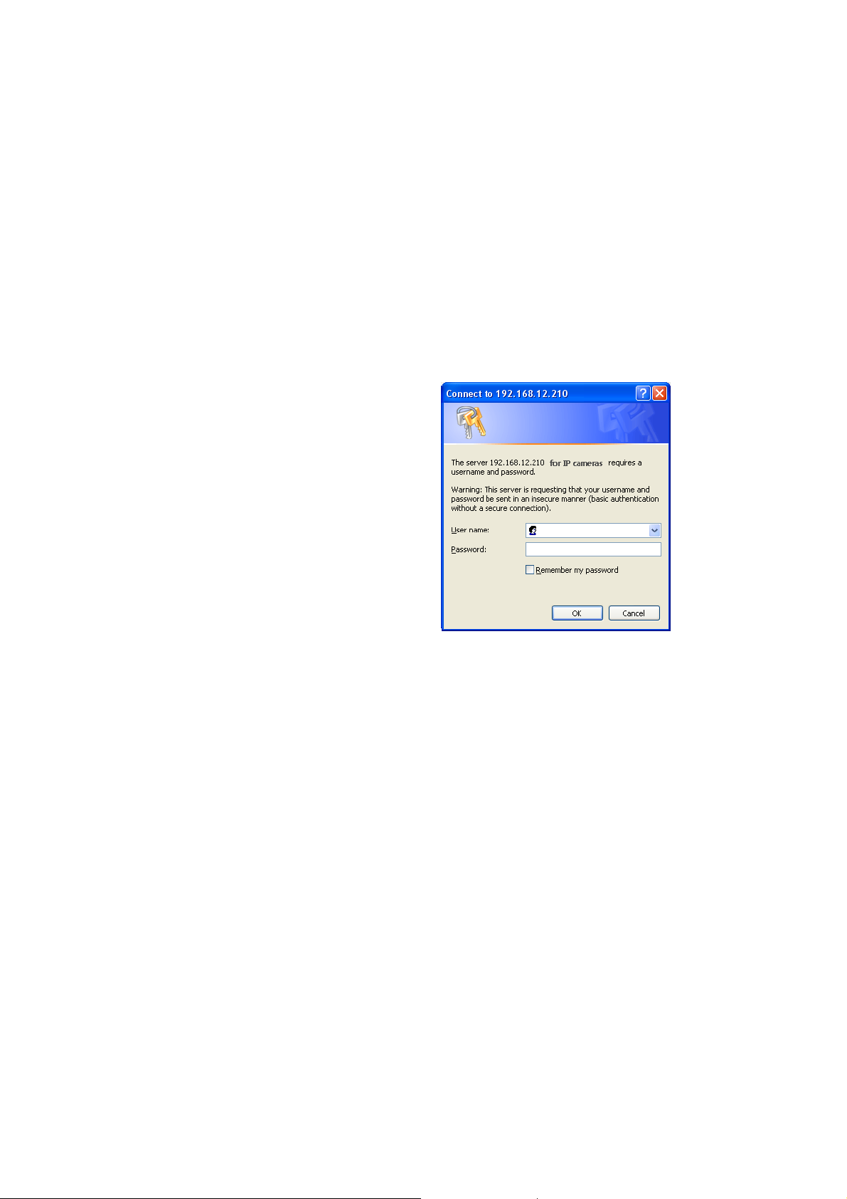
ain access to the product, the password for
he default administrator user must be set. This
is done in the “Admin Password” dialog, which is
displayed when the network
or the setup at the first time. Enter your admin
name and password, set by the administrator.
camera is accessed
Note: The default administrator username is
admin and password is admin. If the password is
lost, the Network Camera must be reset to the
actory default settings. See “3.8 Resetting to the
Factory Default Settin
To prevent network eavesdropping when setting the admin password, this can be done via an
encrypted HTTPS connection, which requires an HTTPS certificate (see note below).
To set the password via a standard HTTP connection, enter it directly in the first dialog shown below.
To set the password via an encrypted HTTPS connection, see “3.5.5 System >Security>HTTPS”.
Note: HTTPS (Hypertext Transfer Protocol over SSL) is a protocol used to encrypt the traffic between
web browsers and servers. The HTTPS certificate controls the encrypted exchange of information.
.
16
Page 17
3.4 Live View Page
T
j
g
he live view page comes in several screen
modes: 1920x1080, 1280x1024, 1280x720,
800x600, 704x480(576), 640x480,
352x240(288) and 320x240. Users are
allowed to select the most suitable one out
of those modes. Please, ad
accordance with your PC specifications and
monitorin
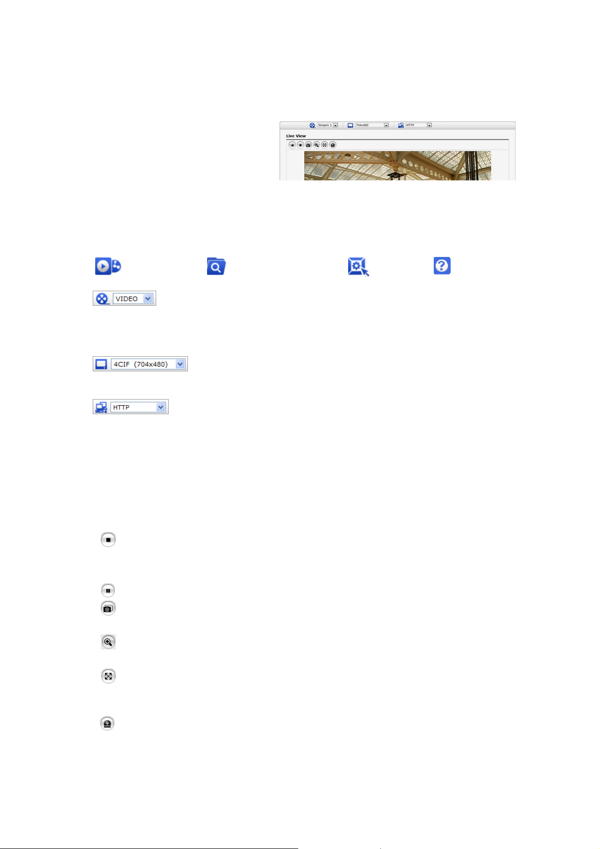
1) General controls
Live View Page Search & Playback Page Setup Page Help Page
2) Control toolbar
start and stop. The Start button connects to the network camera or start playing a
video stream.
purposes.
The video drop-down list allows you to select a customized or pre-programmed
video stream on the live view page. Stream profiles are configured under Setup > Basic
Configuration > Video & Image. For more information, please see “3.5.1 Basic Configuration >
Video & Image” of User’s Manual
The resolution drop-down list allows you to select the most suitable one
out of video resolutions to be displayed on live view page.
The protocol drop-down list allows you to select which combination of
protocols and methods to use depends on your viewing requirements, and on the properties of
your network.
The live viewer toolbar is available in the web browser page only. It displays the following
buttons:
The Stop button stops the video stream being played. Pressing the key again toggles the
ust the mode in
The Pause button pause the video stream being played.
The Snapshot button takes a snapshot of the current image. The location where the
image is saved can be specified.
The digital zoom activates a zoom-in or zoom-out function for video image on the live
screen.
The Full Screen button causes the video image to fill the entire screen area. No other
windows will be visible. Press the 'Esc' button on the computer keyboard to cancel full
screen view.
The Manual Trigger button activates a pop-up window to manually start or stop the event.
17
Page 18

3) Video Streams
The network camera provides several images and video stream formats. Your requirement s and
the properties of your network will determine the type you use.
The Live View page in network camera provides access to H.264, MPEG-4 and Motion JPEG video
streams, and to the list of available video streams. Other applications and clients can also access
these video streams/images directly, without going via the Live View page.
18
Page 19
3.5 Network Camera Setup
This section describes how to configure the network camera, and is intended for product
Administrators, who have unrestricted access to all the Setup tools; and Operators, who have acce ss
to the settings for Basic, Live View, Video & Image and System Configuration.
You can configure the network camera by clicking Setup in the top right -hand corner of the Live View
page. Click on this page to access the online help that explains the setup tools
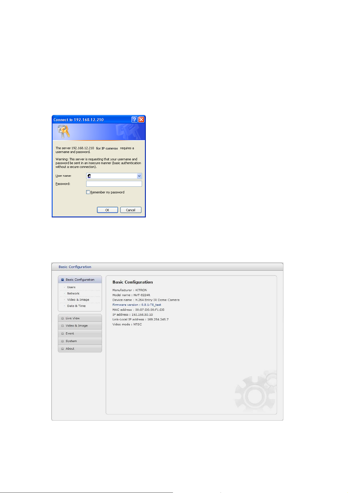
When accessing the Network Camera for the first time,
the “Admin Password” dialog appears. Enter your
admin name and password, set by the administrator.
Note: If the password is lost, the Network Camera
must be reset to the factory default settings. See “3.8
Resetting to the Factory Default Settings”.
3.5.1 Basic Configuration
You can see the device information in this information page.
19
Page 20
1) Users
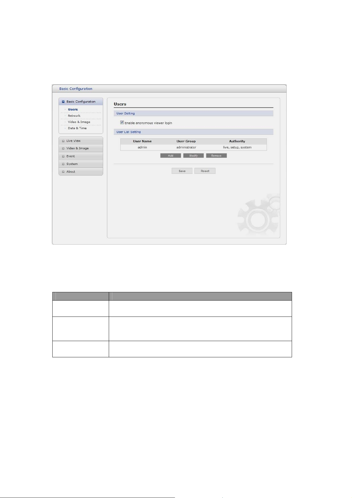
User access control is enabled by default. An administrator can set up other users, by giving these
user names and passwords. It is also possible to allow anonymous viewer login, which means that
anybody may access the Live View page, as described below:
The user list displays the authorized users and user groups (levels):
User Group Authority
Guest
Provides the lowest level of access, which only allows access to the
Live View page.
An operator can view the Live View page, create and modify
Operator
events, and adjust certain other settings. Operators have no access
to System Options.
Administrator
An administrator has unrestricted access to the Setup tools and can
determine the registration of all other users.
Enable anonymous viewer login: Check the box to use the webcasting features. Refer to
“3.5.2 Video & Image” for more details.
20
Page 21
2) Network
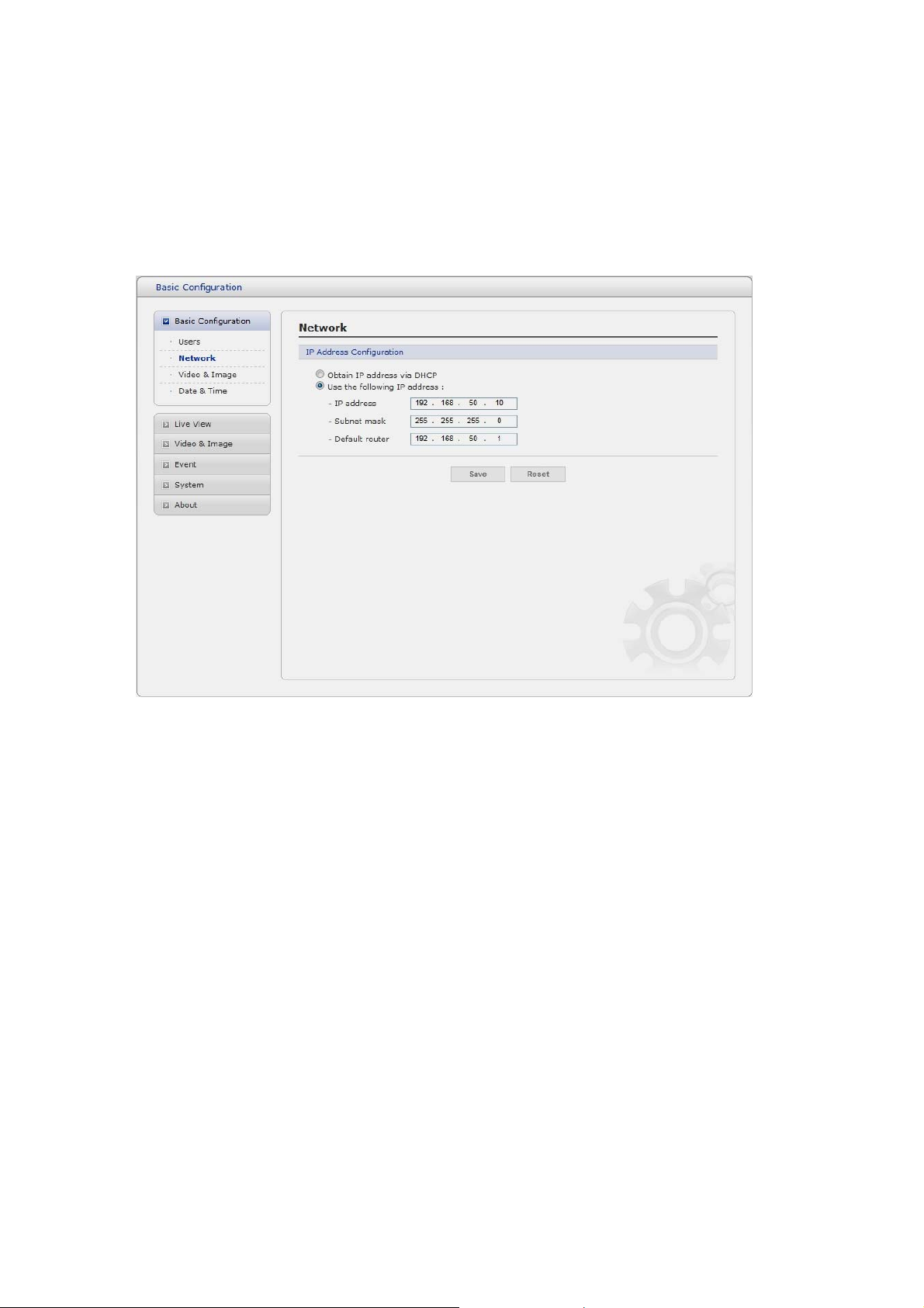
The network camera supports both IP version 4 and IP version 6. Both versions may be enabled
simultaneously, and at least one version must always be enabled. When using IPv4, the IP address for
the network camera can be set automatically via DHCP, or a static IP address can be set manually.
If IPv6 is enabled, the network camera receives an IP address according to the configuration in the
network router. There is also the option of using the Internet Dynamic DNS Service. For more
information on setting the Network, please see Setup> System>Security>Network.
• Obtain IP address via DHCP - Dynamic Host Configuration Protocol (DHCP) is a protocol
that lets network administrators centrally manage and automate the assignment of IP
addresses on a network. DHCP is enabled by default. Although a DHCP server is mostly
used to set an IP address dynamically, it is also possible to use it to set a static, known IP
address for a particular MAC address.
• Use the following IP address - To use a static IP address for the Network Camera,
check the radio button and then make the following settings:
- IP address - Specify a unique IP address for your Network Camera.
- Subnet mask - Specify the mask for the subnet the Network Camera is located on.
- Default router - Specify the IP address of the default router (gateway) used for
connecting devices attached to different networks and network segments.
Notes:
1. DHCP should only be enabled if using dynamic IP address notification, or if your DHCP server can
update a DNS server, which then allows you to access the Network Camera by name (host name).
If DHCP is enabled and you cannot access the unit, you may have to reset it to the factory
default settings and then perform the installation again.
2. The ARP/Ping service is automatically disabled two minutes after the unit is started, or
as soon as an IP address is set.
3. Pinging the unit is still possible when this service is disabled.
21
Page 22
3) Video & Image
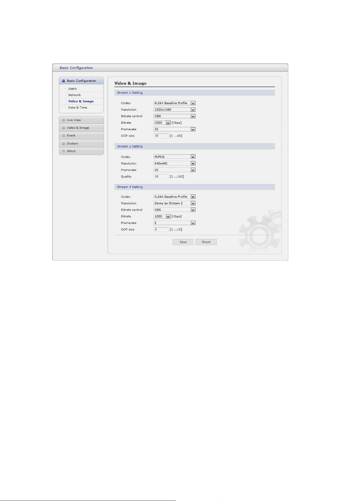
• Stream1 Setting
- Codec:
The codec settings are separated into MPEG4 and H.264.
H.264 is also known as MPEG-4 Part 10. This is the new generation compression standard
for digital video. This function offers higher video resolution than Motion JPEG or MPEG-4 at
the same bit rate and bandwidth, or the same quality video at a lower bit rate.
- Profile:
There are 4 pre-programmed stream profiles available for quick set-up.
Choose the form of video encoding you wish to use from the drop-down list:
* H.264 HP (High Profile): The primary profile for broadcast and disc storage applications,
particularly for high-definition television applications (for example, this is the profile
adopted by the Blu-ray Disc storage format and the DVB HDTV broadcast service).
* H.264 MP
Primarily for low-cost applications that requires additional err or robustness, this profile is
used rarely in videoconferencing and mobile applications, it does add additional error
resilience tools to the Constrained Baseline Profile. The importance of this profile is fading
after the Constrained Baseline Profile has been defined.
(Main Profile):
22
 Loading...