

Page 1
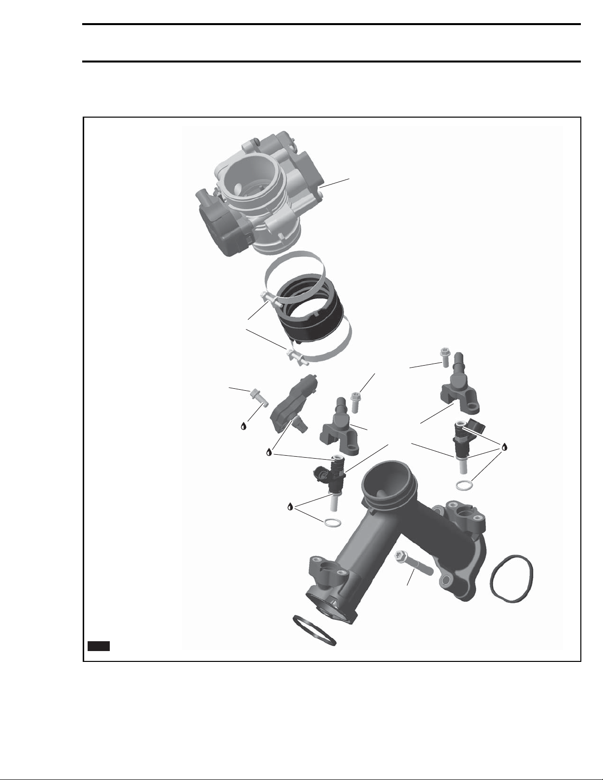
INTAKE MANIFOLD
0,7 ± 0,1 N•m
(6 ± 1 lbf•in)
Subsection 07 (INTAKE MANIFOLD)
See ELECTRONIC FUEL
INJECTION (EFI)
6 ± 0,7 N•m
(53 ± 6 lbf•in)
Loctite 243
Engine oil
= Component must be replaced when removed.
NEW
2016-117-001_a
vmr
10 ± 1 N•m
(89 ± 9 lbf•in)
See
ELECTRONIC FUEL
INJECTION (EFI)
Engine oil
Engine oil
20 ± 2 N•m
(15 ± 1.5 lbf•ft)
vmr2016-418 1
Page 2
Subsection 07 (INTAKE MANIFOLD)
PROCEDURES
INTAKE MANIFOLD
Intake Manifo
Refer to
BODY
ld Access
subsection and remove the follow-
ing:
– Console
– RH side panel and extension.
Removing the Intake Manifold
1. Release fuel pressure. Refer to
AND FUEL PUMP
2. Disconnect t
op of shift rod.
subsection.
FUEL TANK
vmr2015-031-002_a
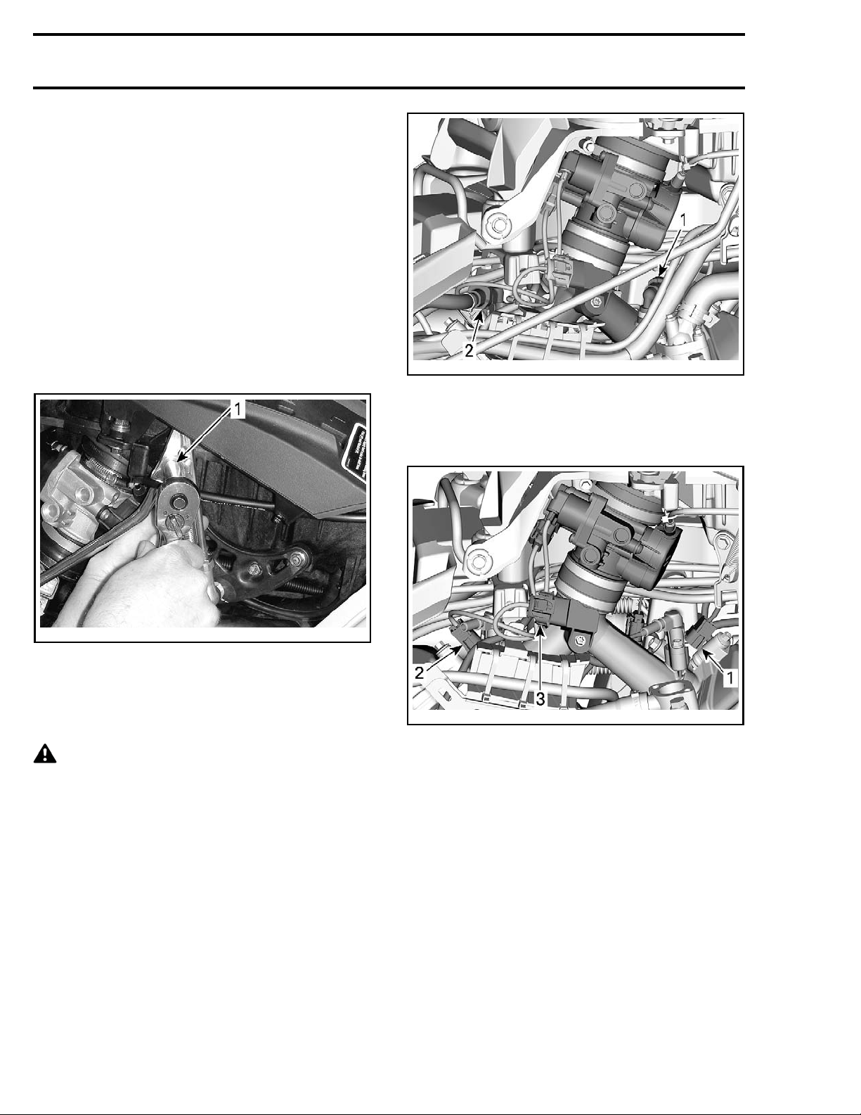
1. Forward fuel rail disconnect
2. Rear fuel rail disconnect
4. Disconnect fuel injector electrical connectors.
5. Disconnect MAPTS connector.
vmr2012-015-006_a
TYPICAL - SHIFT ROD DISCONNECT
1. Remove screw, nut, and bushing
3. Disconnect the fuel hoses from fuel rails, refer
ELECTRONIC FUEL INJECTION (EFI)
to
sub-
section.
CAUTION The fuel hose may still be un-
der pressure.
vmr2015-031-003_a
1. Forward fuel injector connector
2. Rear fuel injector connector
3. MAPTS connector
6. Disconnect throttle body from intake manifold
and air intake silencer. Refer to
FUEL INJECTION (EFI)
subsection.
ELECTRONIC
NOTE: Do not disconnect throttle cable needlessly.
7. Remove wiring harness support from engine.
2 vmr2016-418
Page 3
vmr2012-015-005_a
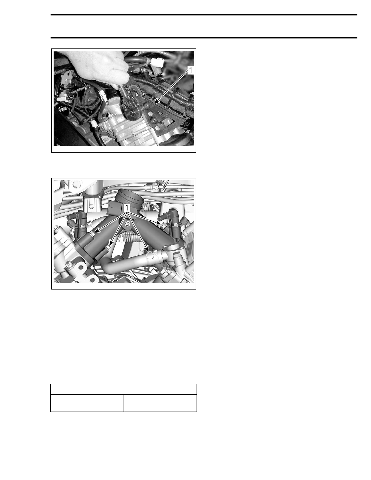
1. Remove
8. Remove intake manifold from engine.
Subsection 07 (INTAKE MANIFOLD)
vmr2015-031-004_a
1. Manifold retaining screws (4x)
Inspecting the Intake Manifold
Check intake manifold for cracks, warping at
flanges or any other damage. Replace if necessary.
Installing the Intake Manifold
The installation is the reverse of the removal procedure. However, pay attention to the following.
Tighten intake manifold retaining screws to specified torque one cylinder at a time.
TIGHTENING TORQUE
Intake manifold
retaining screws
Enable fuel pump using B.U.D.S.
20 N•m ± 2 N•m
(15lbf•ft± 1lbf•ft)
vmr2016-418 3
 Loading...