

Page 1

Subsection 03 (IGNITION SYSTEM)
IGNITION SYSTEM
SERVICE TOOLS
Description Part Number Page
ECM ADAPTER TOOL................................................................... 529 036 166 ......................................... 2, 4
FLUKE 115 MULTIMETER ............................................................ 529 035 868 ......................................... 3–4
GENERAL
SYSTEM DESCRIPTION
The battery supplies the primary side of ignition
coils through the main relay (R2) while the ECM
completes the circuit for each cylinder by switching it to ground at the right moment. The ECM
can detect an open and short circuit in the primary
winding but it does not check the secondary winding.
The Engine Management System (EMS) controls
the ignition system. For more information, refer
ENGINE MANAGEMENT
to
subsection.
Ignition Timing
Ignition timing is not adjustable.
TROUBLESHOOTING
It is good practice to check for fault codes using
the B.U.D.S. software as a first troubleshooting
step. Refer to
DIAGNOSTIC AND FAULT CODES
subsection.
Always refer to the
WIRING DIAGRAM
when
troubleshooting an electrical circuit.
Refer to
POWER DISTRIBUTION AND GROUNDS
for fuse and relay information.
Refer to
WIRING HARNESS AND CONNECTORS
for vehicle wiring harness layout and component
locations.
Refer to
ENGINE MANAGEMENT SYSTEM (EMS)
for powertrain wiring harness layout and component locations.
DIAGNOSTIC GUIDELINES
The following is provided to help in diagnosing the
probable cause of a problem. It is a guideline and
should not be assumed to list all possible causes.
ENGINE WILL NOT START (ENGINE
TURNS OVER)
2. Defective CPS
- Check operation of CPS and replace if necessary.
Refer to ELECTRONIC FUEL INJECTION (EFI)
subsection.
3. Defective trigger wheel
- Inspect trigger wheel. Refer to MAGNETO AND
STARTER subsection.
4. Defective ignition circuit
- Check fuse 5 of fuse box 1, ignition coil and wiring
condition.
5. Defective fuel pump
- Check fuel pump, refer to FUEL TANK AND FUEL
PUMP subsection.
6. Defective fuel injectors or circuit
- Check fuel injectors, refer to ENGINE MANAGEMENT SYSTEM subsection.
ENGINE HARD TO START
1. Spark plug faulty, fouled or worn out
- Check spark plug condition. Replace if necessary.
2. Low fuel pressure
- Test fuel pressure, refer to FUEL TANK AND
FUEL PUMP subsection.
ENGINE MISFIRES, RUNS IRREGULARLY
1. Fouled, defective, worn spark plugs
- Check/verify heat range/gap/replace.
2. Damaged trigger wheel/loose CPS
- Inspect trigger wheel. Refer to MAGNETO AND
STARTER subsection.
3. Defective ignition circuit
- Check ig nition coil, fu se 5, and wiring condition.
4. Poor engine grounds
- Check/clean/repair.
ENGINE CONTINUALLY BACKFIRES
1. Fouled, defective spark plugs
- Clean/replace spark plugs.
1. Fouled or defective spark plug
-Replace.
vmr2016-134 1
Page 2
Subsection 03 (IGNITION SYSTEM)
2. Damaged trigger wheel/defective or loose CPS
- Inspect trigger wheel and CPS , refer to MAGNETO AND STARTER and ELECTRONIC FUEL
INJECTION (EFI) subsections.
PROCEDURES
IGNITION SWITCH
Ignition Switch Quick Test
Turn ignition switch to ON position.
If multifunction gauge turns on (assuming it
works), the ignition switch is good.
If multifunction gauge does not turn on, check the
following in this order:
– Battery
– Fuse link 1
– Fuse 4, 5 and 8 of fuse box 1
– ECM is properly powered (refer to
TRONIC FUEL INJECTION (EFI)
subsection)
– Ignition switch
– Emergency engine stop switch.
Ignition Switch Access
Refer to
side panel.
BODY
subsection and remove the LH
ELEC-
EMERGENCY ENGINE STOP
SWITCH
Testing the Emergency Engine Stop
Switch at ECM
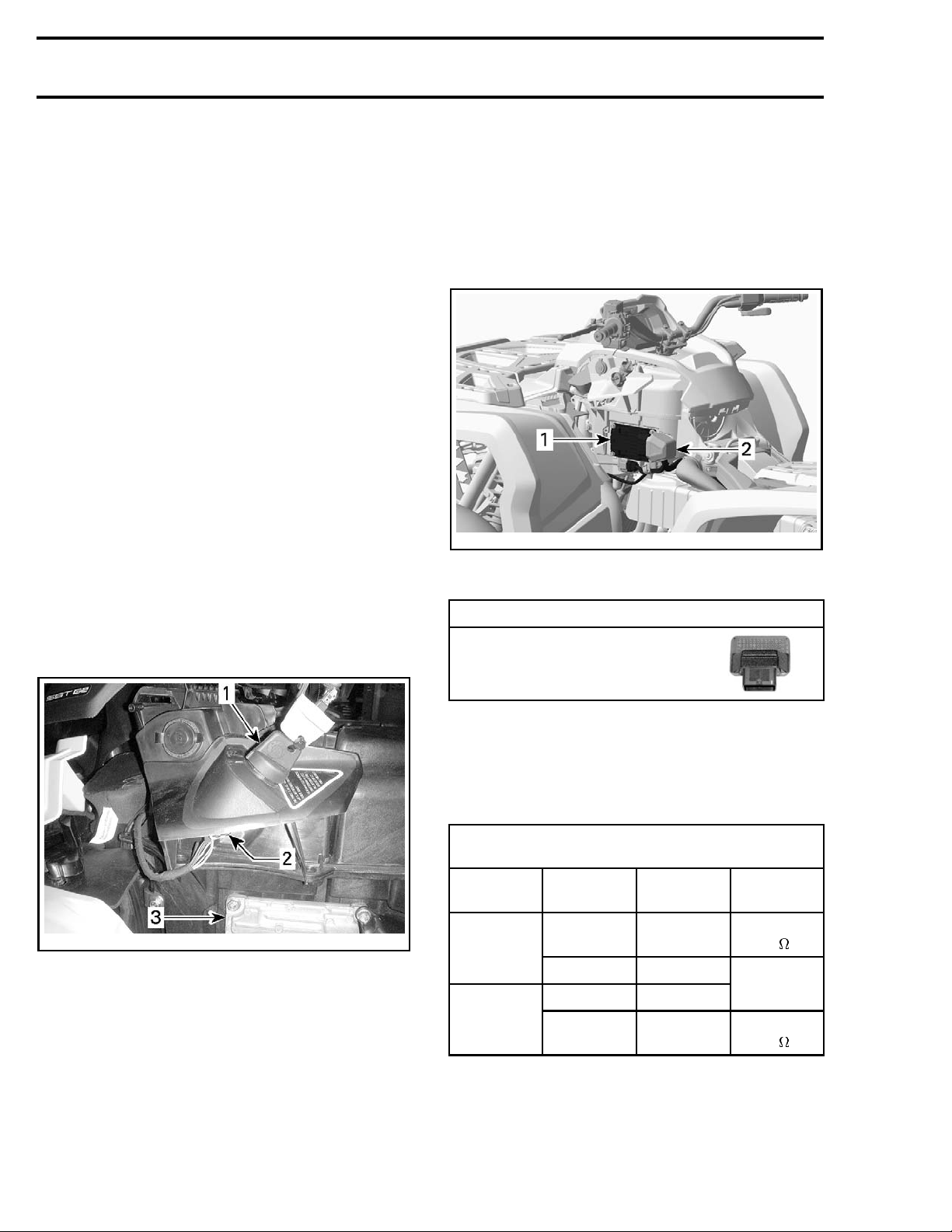
1. Disconnect ECM connector and install it on the
ECM adapter tool.
vmr2012-031-005_b
TYPICAL
1. ECM
2. ECM connector cover
REQUIRED TOOL
ECM ADAPTER TOOL
(P/N 529 036 166)
vmr2012-031-001_a
TYPICAL
on key
1. Igniti
2. Ignition switch conne ctor
3. ECM
2. Remove ignition key switch fuse (F8), refer to
POWER DISTRIBUTION AND GROUNDS
sub-
section.
3. Turn ignition key to ON position.
4. Test for continuity as per following table.
EMERGENCY ENGINE STOP SWITCH
TESTATECM
FUNCTION
RUN
position
STOP
position
FUSE BOX
CONTACT
5E A4
—
5E A4
—
If switch fails the test, refer to
ECM
ADAPTER
G2 to K3
G2 to K3
RESULT
Close to
0
Open
circuit
Close to
0
TESTING THE
EMERGENCY ENGINE STOP SWITCH AT MULTIFUNCTION SWITCH CONNECTORS
.
2 vmr2016-134
Page 3
Testing the Emergency Engine Stop
Switch at Multifunction Switch
Connectors
Refer to
subsection for connector locations.
The emergency engine stop switch is wired into
the LH multifunction switch connectors (MG1 and
MG2).
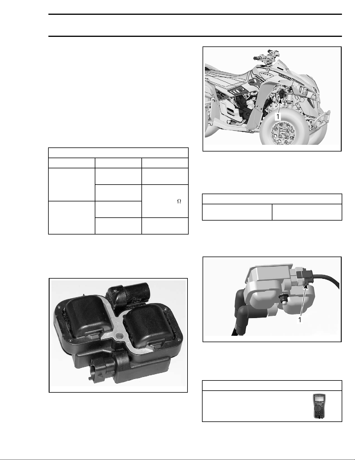
1. Remove gauge support, refer to
GAUGE AND ACCESSORIES
2. Disconnect MG1 and MG2 connectors.
3. Test switch continuity as per following table.
EMERGENCY ENGINE STOP SWITCH PIN-OUT
RUN position
STOP position
If switch tests good, test continuity of wiring. Refer to
WIRING HARNESS AND CONNECTORS
LIGHTS,
subsection.
FUNCTION PROBE RESULT
MG1-3 to
MG2-3
MG1-1 to
MG1-2
MG1-3 to
MG2-3
MG1-1 to
MG1-2
WIRING DIAGRAM
.
Open circuit
Closeto0
Open circuit
Subsection 03 (IGNITION SYSTEM)
1-002_a
vmr2012-03
TYPICAL
1. Ignition coil location
Installing
the Ignition Coil
Install a new elastic nut and tighten to the specified torque.
TIGHTENING TORQUE
Ignition coil retaining bolt
8N•m ± 1N•m
(71 lbf•in ±9lbf•in)
Testing the Ignition Coil Input Voltage
1. Disconnect the 3-pin connector from the ignition coil. Refer to
IGNITION COIL ACCESS
.
IGNITION COIL
06-018-100
vmr20
Ignition Coil Access
Refer to
fender panel(s) for access to the ignition coil.
BODY
subsection and remove RH inner
tmr2011-026-002_a
1. Ignition coil connector
2. Set emergency engine stop switch to RUN.
3. Turn ignition switch to ON.
4. Read voltage as per following table.
IRED TOOL
REQU
FLUKE 115 MULTIMETER
(P/N 529 035 868)
vmr2016-134 3
Page 4
Subsection 03 (IGNITION SYSTEM)
IGNITION COIL I
CONNECTORS VOLTAGE
Pin 2 with battery ground Battery voltage
NPUT VOLTAGE TEST
If battery voltage is NOT read, check continuity of
ignition coil supply circuit. Refer to
GRAM
.
WIRING DIA-
Testing the Ignition Coil Ground Circuit
Continuity
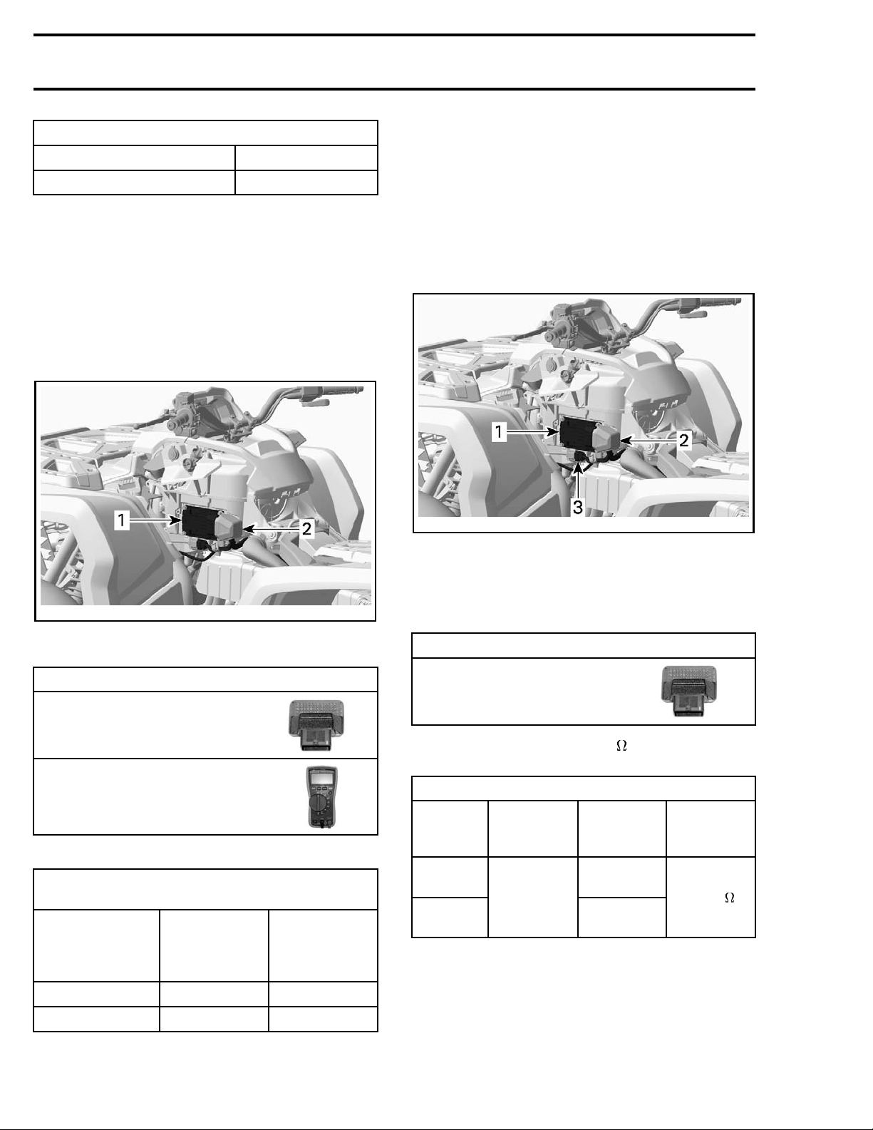
1. Disconnect the ECM connector and connect
it to the ECM adapter tool. Refer to
TRONIC FUEL INJECTION (EFI)
subsection.
ELEC-
Testing the Ignition Coil Resistance
An ignition coil with good resistance measurement can still be faulty. Voltage leakage can occur
at high voltage levels which is not detectable with
an ohmmeter. Replacing the ignition coil may be
necessary as a test.
Primary Windings
1. Disconnect HIC2 connector.
vmr2012-031-005_a
TYPICAL
1. ECM
2. ECM connector cover
3. HIC2 connector
031-005_b
vmr2012-
TYPICAL
1. ECM
2. ECM conn
FLUKE 115 MULTIMETER
ector cover
REQUIRED TOOLS
ECM ADAPTER TOO L
(P/N 529 036 166)
(P/N 529 035 868)
2. Check wiring continuity as per following table.
IGNITION COIL GROUND CIRCUIT
CONTINUITY TEST
COMPO
Cylinder 1 (front)
Cylinder 2 (re ar)
NENT
PIN
(IGNITION
COIL
CONN
ECTOR)
1
3M2
PIN
(ECM
CONNECTOR)
M1
2. Disconnect ECM connector and connect it to
the ECM adapter tool.
REQUIRED
ECM ADAPTER TOOL
(P/N 529 036 166)
TOOL
3. Using a multimeter set to , check resistance
in primary windings as follows.
ON COIL RESI STANCE TEST
IGNITI
PRIMAR
CIRCUIT
Cylinder 1
(front)
der 2
Cylin
(rear)
Y
CONNECTOR
ENGINE
(HIC2)
Pin C
ECM
CONNECTOR
M1
M2
RESISTANCE
@ 20°C
(68°F)
.3 - .6
If any resistance is not good, measure resistance
directly on coil. If second test is ok, check wiring.
Secondary Windings
o the integrated diode, it is not possible
Due t
ke any resistance measurement of the sec-
to ta
ry winding.
onda
4 vmr2016-134
Page 5
SPARK PLUG
For spark plug replacement procedure, refer to
PERIODIC MAINTENANCE PROCEDURES
section.
Troubleshooting Fouled Spark Plug
Fouling of the spark plug is indicated by irregular
running of the engine, decreased engine speed
due to misfiring, reduced performance, and increased fuel consumption. This is due to a loss
of compression. Other possible causes are: prolonged idling or low-speed riding, a clogged air
filter, incorrect fuel, defective ignition system,
incorrect spark plug gap, lubricating oil entering
the combustion chamber, or too cold spark plug.
The plug face of a fouled spark plug has either a
wet black deposit or a black carbon fouling. Such
coatings form a conductive connection between
the center electrode and ground.
sub-
Subsection 03 (IGNITION SYSTEM)
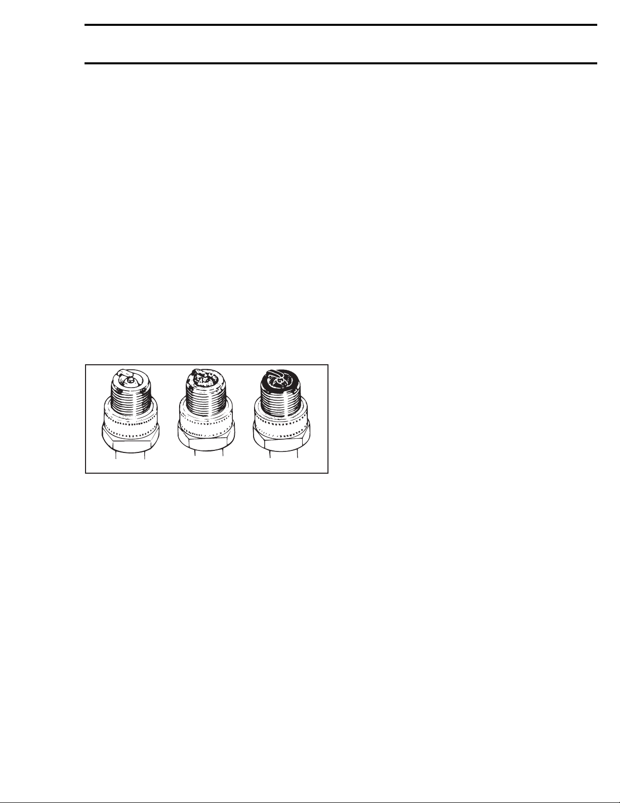
Spark Plug Analysis
A00E0AA
TYPICAL
1. Overheated (light grey, white)
2. Normal (light brown, brown)
3. Fouled (black, wet or dry, dark deposits, grey, melted coating)
The plug face reveals the condition of the engine,
operating condition, method of driving and fuel
mixture. For this reason it is advisable to inspect
the spark plug at regular intervals, examining the
plug face (i.e. the part of the plug projecting into
the combustion chamber).
123
vmr2016-134 5
 Loading...