

Page 1
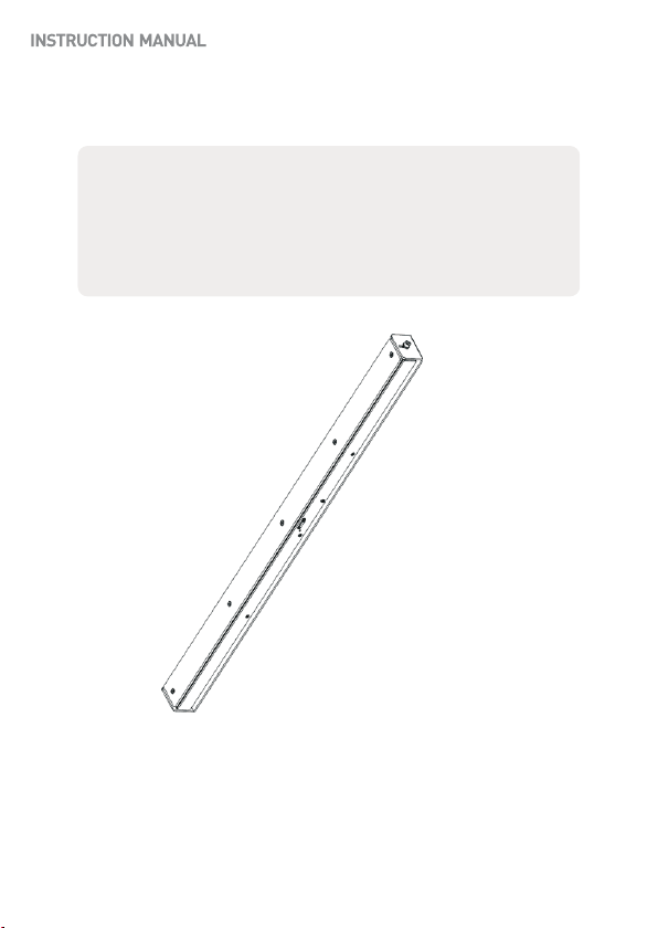
Height Strip Covert Camera
Please read this manual thoroughly before use, and keep it handy for future reference.
Design and specifications are subject to change without notice.
Page 2
FCC COMPLIANCE STATEMENT
2
This device complies with Part 15 of the FCC Rules. Operation is subject to the following two
conditions: (1) this device may not cause harmful interference, and (2) this device must
accept any interference received, including interference that may cause undesired operation.
FCC INFORMATION : This equipment has been tested and found to comply with the limits
for a Class A digital device, pursuant to Part 15 of the FCC Rules. These limits are designed
to provide reasonable protection against harmful interference when the equipment is
operated in a commercial environment. This equipment generates, uses, and can radiate
radio frequency energy and, if not installed and used in accordance with the instruction
manual, may cause harmful interference to radio communications. Operation of this
equipment in a residential area is likely to cause harmful interference in which case the user
will be required to correct the interference at his own expense.
CAUTION : Changes or modifications not expressly approved by the party responsible for
compliance could void the user’s authority to operate the equipment.
CE COMPLIANCE STATEMENT
WARNING : This is a Class A poduct. In a domestic environment this product may cause
radio interference in which case the user may be required to take adequate measures.
Page 3
IMPORTANT SAFETY INSTRUCTIONS
3
1. Read these instructions.
2. Keep these instructions.
3. Heed all warnings.
4. Follow all instructions.
5.. Do not block any ventilat ion openings. Install in accord ance with the manufacturer`s
instructions.
6. Do not install near any heat sources such as radiators, heat r egisters, stoves, or other
apparatus (including amplifiers) that produce heat.
7. Only use attachments/accessories specified by the manufacturer.
8. Use only with the ca rt, stand, tripod, bracket, or table specified by
the manufacturer, or sold with the apparatus. When a cart is used,
use caution when moving the cart/ apparatus combination to avoid
injury from tip-over.
9. CAUTION - THESE SERVICING IN STRUCTIONS ARE FOR USE BY
QUALIFIED SERVICE PERSONNEL ONLY. TO REDUCE THE RISK OF
ELECTRIC SHOCK DO NOT PERFORM ANY SERVICING OTHER THAN
THAT CONTAINED IN THE OPERATING INSTRUCTIONS UNLESS YOU
ARE QUALIFIED TO DO SO.
10. Use satisfy clause 2.5 of IEC60950-1/UL 60950-1 or Certified/Listed Class 2
power source only.
11. Indoor use only.
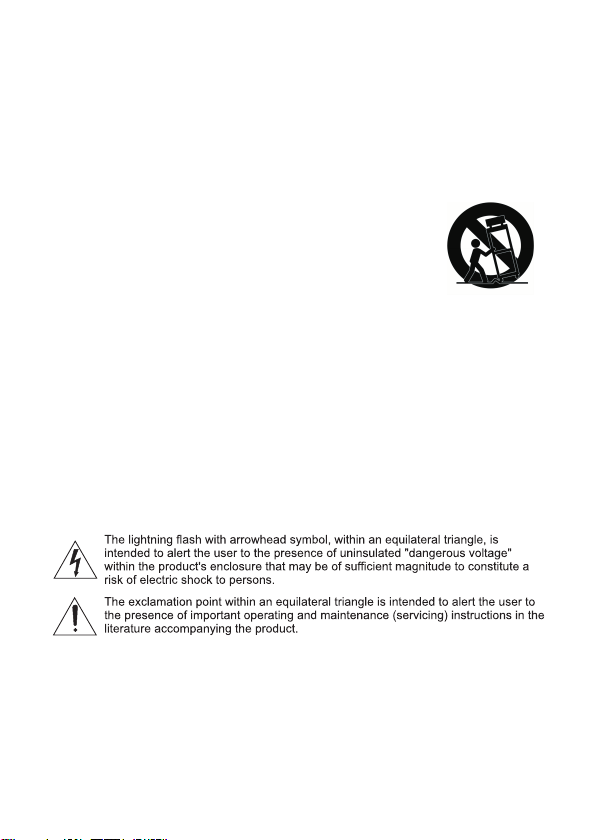
EXPLANATION OF GRAPHICAL SYMBOLS
Page 4
4
Page 5
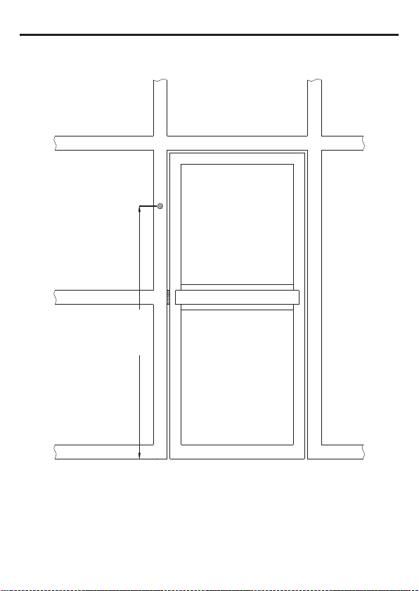
Step 1
5
63.2 7"
Drill feed-thru hole for cable on mounting surface 63.27" above the finished floor.
Page 6
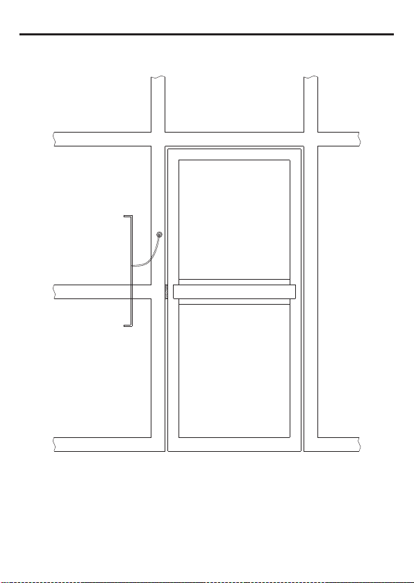
Step 2
6
Feed wire through the 1.0 inch hole on the gimble mount.
Page 7
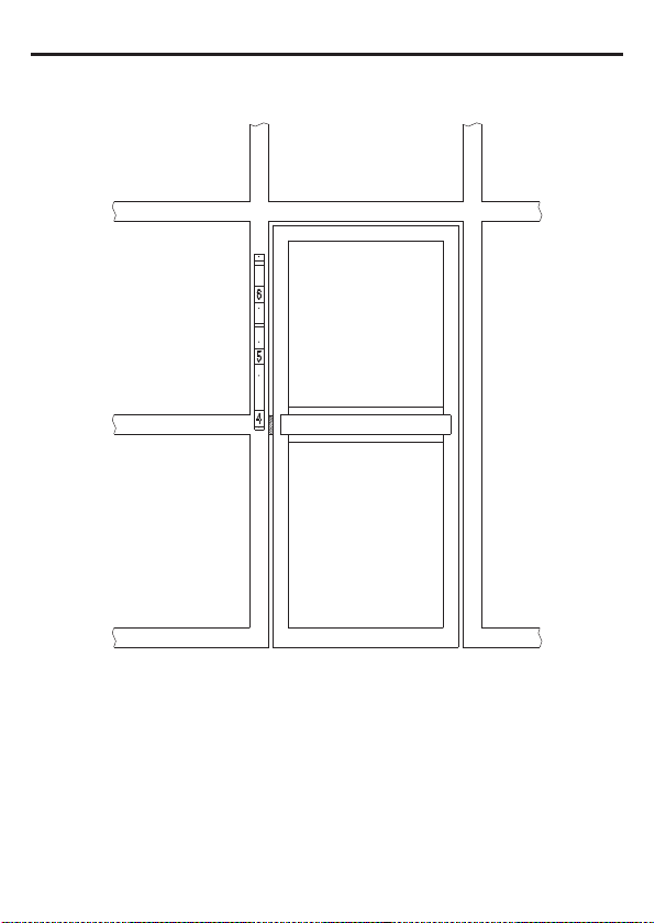
Step 3
7
Center the gimbal mount to mounting surface and mark the mounting holes for the gimbal mount on
the surface.
Secure the gimbal mount to the surface using installer supplied self tappers for aluminum frame
structure.
If mounting on soft surface such as drywall be sure to use to use anchors.
Page 8

Step 4
8
Completing the housing installation
Remove the five white head M4 screws that hold the face plate to the housing
and set the face plate aside.
Feed the wire coming through the gimbal mount through the 3/4" hole in the
back of the camera housing.
Attach the camera housing to the gimbal mount using the M6 Allen head screws
and washer previously removed.
Place the external tooth washer between the housing and the gimbal mount then
the split lock washer on the M6 screw and insert the screw into the housing
through the gimbal mount and external tooth lock wasker.
Install the bolt and washers assembly at the bottom and top of the gimbal mount
finger tight. (See Figure-1)
M6 Allen head screw
Split lock washer between gimbal mount and housing
External tooth lock washer under head of bolt
Figure-1
After connecting the video and power to their proper connections replace the
face plate that was removed in an earlier step using the five screws.
Adjust the position of the housing in the gimbal mount for the proper view and
then tighten the top and bottom Allen head screws using an Allen head wrench.
Verify that the housing is in the proper position and is secure.
Page 9

Optional Camera Height Setting
9
1. The Height strip camera has the capability to be set in the housing at 5ft or
5.5ft above the floor.
The default setting of the camera is set to 5.5ft.
If the lower setting is desired the following housing change must be
completed.
* Remove housing from gimbal
1
* Note the position of the hole in the housing base for cable throughput
2
Figure-2
[ft] [cm]
Figure-3
The cable hole is at the center of the mounting bracket
* Remove four Allen flat head screws along each side of the housing and
separate the front cover with the camera from the housing base.
Allen flat head screw
* Replace the front cover with the camera to the housing base after
turning the cover 180 f r
Replace the three Allen head screws along each side of the housing
and continue the installation
o
om original position.
2
1
* From to to change the camera position. (See Figure-2)
2. Camera lens position can be adjusted up and down 5 degrees.
o
5
3. Two height marker strips are provided, one marked in feet
and one marked in centimeters. Use the appropriate one.
(See Figure-3)
o
5
Page 10

DIMENSIONS
10
HEIGHT STRIP CAMERA
Page 11

STRUCTURE OF THE SETUP MENU
<SETUP>
LENS
EXPOSURE
BACKLIGHT
WHITE BAL
DAY&NIGHT
IMAGE
FUNCTION
SYSTEM
EXIT
<LENS>
DC
MANUAL
<EXPOSURE>
SHUTTER
AGC
SENS-UP
BRIGHTNESS
D-WDR
DEFOG
RETURN
<BACKLIGHT>
OFF
BLC
HSBLC
<WHITE BAL>
ATW
AWC->SET
INDOOR
OUTDOOR
MANUAL
AWB
<DAY&NIGHT>
AUTO
COLOR
B&W
<IMAGE>
SHARPNESS
LSC
D-EFFECT
RETURN
<FUNCTION>
DNR
MOTION
PRIVACY
DEFECT DET
RETURN
<SYSTEM>
CAMTITLE
MONITOR
VIDEO OUT
LANGUAGE
COMET
RETURN
<RESET>
SAVE&END
RESET
NOT SAVE
11
Page 12

MAIN MA NU
LENS DC
EXPOSURE
BACK LIGHT OFF
SHUTTER AUTO
AGC
SENS-UP
|▪▪▪l▪| 11
AUTO
WHITE BAL
DAY&NIGHT
IMAGE
FUNCTION
SYSTEM
EXIT
ATW
AUTO
BRIGHTNESS |▪▪l▪▪| 48
D-WDR
DEFOG
RETURN
OFF
OFF
RET
SAVE&END
MAIN MA NU
LENS DC
EXPOSURE
BACK LIGHT OFF
MAIN MA NU
LENS MANUAL
EXPOSURE
BACK LIGHT OFF
WHITE BAL
DAY&NIGHT
IMAGE
FUNCTION
SYSTEM
EXIT
ATW
AUTO
SAVE&END
WHITE BAL
DAY&NIGHT
IMAGE
FUNCTION
SYSTEM
EXIT
ATW
AUTO
SAVE&END
NOTE Choose when installed in an external DC mode outdoor.
12
LENS
The EXPOSURE menu is used to set the automatic light control method for the camera.
It provides the ability to adjust the SHUTTER speed. AGC SENS-UP, BRIGHTNESS, D-WDR,
and DEFOG functions of the camera.
1) DC Select the DC mode.
Select the DC iris speed ▶ 0~15
2) MANUAL
Select the
MANUAL mode
▶
INDOOR, OUTDOOR
EXPOSURE
The EXPOSURE menu is used to set the automatic light control method for the camera.
It provides the ability to adjust the SHUTTER speed, AGC, SENS-UP, BRIGHTNESS, D-WDR,
and DEFOG functions of the camera.
1) SHUTTER Select the SHUTTER speed level.
▶
Auto, 1/60(50), FLK~1/240 – 1/50000, x2 ~ x30
2) AGC Adjust the Auto Gain Control level.
3) SENS-UP
4) BRIGHTNESS
5) D-WDR
Select the Digital Slow Shutter level. ▶
Adjust the BRIGHTNESS level. ▶
Select the Digital WDR. ▶ AUTO, ON(level 0~8), OFF
6)DEFOG Select the DEFOG mode.▶ AUTO, ON(level 0~8), OFF
POS/SIZE Adjust the window position & size
GRADATION ▶ 0 ~ 2
DEFAULT Initialize the setting values
< EXPOSURE > MODE
▶ OFF, Auto (x2 ~ x30)
0 - 100
OFF, AUTO (x2 ~ x30)
Page 13

BACKLIGHT
MAIN MA NU
LENS DC
EXPOSURE
BACK LIGHT OFF
BLC
WHITE BAL
DAY&NIGHT
IMAGE
FUNCTION
SYSTEM
EXIT
ATW
AUTO
LEVEL
AREA
DEFAULT
RETURN
MIDDLE
RET
HLBL C
SELECT
DISPLAY
AREA
ON
SAVE&END
BLACK MASK ON
LEVEL
MODE
DEFAULT
RETURN
|▪▪l▪▪| 30
ALL DAY
RET
13
The BACKLIGHT menu is used to the ability to prevent back lighting from the image.
1)
BLC
2)HSBLC Mask the high light zone with specific color & level.
< BACKLIGHT >
Prevents such a back light effect to secure a clear image under All illumination
environments.
Adjust the size of Back Light Compensation area.
LEVEL
AREA
DEFAULT
SELECT
DISPLAY
BLACK MASK
LEVEL
MODE
DEFAULT
Select the BLC gain ▶ Low, Middle, High
Adjust the window position & size
Initialize the setting values
Select the HSBLC area ▶ AREA1 - AREA4
Adjust the HSBLC area window position & size
Select the BLACK MASK ▶ ON, OFF
Select the HSBLC level ▶ 0 ~ 100
All Day, Night
Initialize the setting values.
Page 14

WHITE BALANCE
MANU AL
BLUE |▪▪I▪▪| 50
RED |▪▪I▪▪| 50
RETURN RET
MAIN MA NU
LENS DC
EXPOSURE
BACK LIGHT OFF
WHITE BAL ATW
DAY&NIGHT AUTO
IMAGE
FUNCTION
SYSTEM
EXIT SAVE&END
14
The screen color can be adjusted by using the Auto White Balance function.
It compensates for deviations in the white color caused by changes in the color temperature of
the light source so that the colors are reproduced correctly.
1)ATW Automatically adjust color temperature.
2)AWC->SET Automatically readjust only by pressing AWC→SET.
3)INDOOR Set the color temperature to 3200°K
4)OUTDOOR Set the color temperature to 6300°K
5)MANUAL Manual mode.
User can change Red and Blue gain value manually.
BLUE 0 ~ 100
RED 0 ~ 100
6)AWB Automatically extended range of color temperature adjustment.
< WHITE BALANCE > MODE
Page 15

15
DAY&NIGHT
The DAY&NIGHT menu is used to configure the day and night related.setting for the camera.
1) D&N AUTO
-Input Method CDS
D&N LEVEL Adjust levels of transition ▶ 0 - 255
N&D LEVEL Adjust levels of transition ▶ 0 - 255
DELAY 1-60 SEC
-Input Method AGC
N&D LEVEL Adjust levels of transition ▶ 0 - 255
DELAY 1-60 SEC
< DAY&NIGHT > MODE
DAY&NIGHT mode are changed according to the sensor inputs
DAY&NIGHT mode are changed according to the brightness of the image.
Use only when the camera is installed in a dark place but the camera is viewing
a bright place.
When used in a normal installation, hunting may occur.
D&N LEVEL Adjust levels of transition ▶ 0 - 255
2) D&N B&W
IR SMART LEVEL 1~15
LENS DC D N (CDS) |▪▪▪I▪| 206
EXPOSURE D N (DELAY) |▪I▪▪▪| 3
BACK LIGHT OFF N D (CDS) |▪▪▪I▪| 180
WHITE BAL
DAY&NIGHT
IMAGE
FUNCTION
SYSTEM
EXIT
AREA Adjust the window position & size.
MAIN MANU
ATW
AUTO
SAVE&END
D&N AUTO
N D (DELAY) |▪I▪▪▪| 3
RETURN RET
B&W
IR SMART
RETURN
ON
RET
Page 16

D-EF FECT
FREEZE OFF
MIRROR OFF
NEG. IMAGE OFF
RETURN RET
IMAG E
SHARPNESS AUTO
LSC
D-EFFECT
RETURN
OFF
RET
SHAR PNESS
LEVEL
|▪▪I▪▪| 5
SMART AGC |▪▪▪I▪| 128
END AGC |▪▪▪I▪| 160
RETURN RET
IMAG E
SHARPNESS
LSC
D-EFFECT
RETURN
AUTO
OFF
RET
MAIN MA NU
LENS DC
EXPOSURE
BACK LIGHT OFF
ATW
AUTO
IMAG E
SHARPNESS AUTO
LSC OFF
D-EFFECT
RETURN
WHITE BAL
DAY&NIGHT
IMAGE
FUNCTION
SYSTEM
EXIT
RET
SAVE&END
16
The IMAGE menu provides the ability to adjust the SHARPNESS, LSC and D-EFFECT functions
of the camera.
1)
SHARPNESS
2) LSC
3) D-EFFECT FREEZE
Adjust the SHARPNESS level. ▶ OFF, AUTO (0 - 10)
Select the lens Lens Shading Compensation. ▶ ON, OFF
MIRROR Select OFF, MIRROR, V-FLIP, ROTATE
NEG. IMAGE
Select real or still mode ▶ ON, OFF
Select Negative image mode ▶ ON, OFF
< SHARPNESS >
< D-EFFECT >
Page 17

FUNCTION
MAIN MA NU
LENS DC
EXPOSURE
BACK LIGHT OFF
FUNCTION
WHITE BAL
DAY&NIGHT
IMAGE
FUNCTION
SYSTEM
EXIT
ATW
AUTO
DNR
MOTION OFF
PRIVACY OFF
DEFECT DET
RETURN
SAVE&END
17
The IMAGE menu provides the ability to adjust the DNR, MOTION, PRIVACY and
DEFECT DET functions of the camera.
1) DNR
2D
3D
2) MOTION
SELECT
DISPLAY
SENSITIVITY
COLOR Select the motion area color ▶WHITE - Red, Green, Blue
TRANS Select the motion area transparency.▶1.0, 0.75, 0.5, 0.25
ALARM Select the Motion alarm
VIEW TYPE
OSD VIEW
TIME
DEFAULT
3) PRIVACY
SELECT
DISPLAY
COLOR
TRANS
DEFAULT
4) DEFECT DET
LIVE DPC
AGC LEVEL
LEVEL
WHITE DPC
POS/SIZE
START
DPC VIEW ▶ OFF, ON
LEVEL
AGC
SENS-UP
BLACK DPC
POS/SIZE
START
DPC VIEW ▶ OFF, ON
LEVEL
<FUNCTION>
Select Digital Noise Reduction.
▶
OFF, LOW, MIDDLE, HIGH
▶
OFF, LOW, MIDDLE, HIGH
Detects the Motioned Object in the image. ▶ ON, OFF
Select the Motion area ▶ AREA1 - AREA4
Adjust the Motion area window position & size
Adjust the Motion sensitivity level ▶ 0 - 100
Select view type of the Motion area ▶ OFF, BLOCK, OUTLINE, ALL
Select the Motion OSD view ▶ OFF, ON
Select the Motion Alarm time ▶ 1 - 15
Initialize the setting values
Hide an area you want to hide on the screen.
Select the privacy zone ▶ AREA1 - AREA4
Adjust the Privacy window type, position & size
▶ OFF, INV., MOSAIC, COLOR
Select the privacy zone color ▶ WHITE - USER
Select the privacy zone transparency ▶ 1.0, 0.75, 0.5, 0.25
Initialize the setting values
Compensates for bad pixels.
Select the Live DPC mode ▶OFF, ON
Select the AGC level ▶ 0 - 255
Select the Live DPC level ▶ 0 - 100
Select the White DPC mode ▶ OFF, ON
Adjust the White DPC area window position & size
Start the white pixels correction
Select the White DPC level ▶ 0 - 60
Select the AGC Level ▶ 0 - 14
Select the Sens-up level ▶ x2 - x30
Select the Black DPC mode ▶ OFF, ON
Adjust the Black DPC area window position & size
Start the Black pixels correction
Select the Black DPC level ▶ 0 - 100
Page 18

<DNR>
WAITING...
CLOSE THE IRIS
THEN
PRESS ENTER
FUNCTION
DEFECT DET
DNR
MOTION
PRIVACY
DEFECT DET
RETURN
OFF
OFF
LIVE DPC
WHITE DPC
BLACK DPC
RETURN
ON
ON
OFF
RET
LIVE DPC
AGC LEVEL |▪I▪▪▪| 4
LEVEL
|▪I▪▪▪| 2
RETURN RET
RET
DEFECT DET
LIVE DPC ON
WHITE DPC ON
BLACK DPC OFF
RETURN RET
WHITE DPC
POS/SIZE
START
DPC VIEW OFF
LEVEL
|▪▪▪▪| 4
AGC |▪▪▪▪| 14
SENS-UP X2
RETURN RET
FUNCTION
DNR
MOTION
PRIVACY
DEFECT DET
RETURN
OFF
OFF
RET
PRIVACY
SELECT
DISPLAY
COLOR
TRANS
DEFAULT
RETURN
AREA1
COLOR
WHITE
1.0
RET
FUNCTION
DNR
MOTION
PRIVACY
DEFECT DET
RETURN
OFF
OFF
RET
<PRIVACY>
MOTION
SELECT
DISPLAY
SENSITIVITY
COLOR
TRANS
ALARM
DEFAULT
RETURN
AREA1
ON
|▪I▪▪▪| 10
WHITE
1.0
RET
DNR
2D
3D
RETURN
MIDDLE
MIDDLE
OFF
FUNCTION
DNR
MOTION
PRIVACY
DEFECT DET
RETURN
OFF
OFF
RET
18
<MOTION>
<DEFECT DET>
DEFECT DET BLACK DPC
LIVE DPC
WHITE DPC
BLACK DPC
RETURN
ON
ON
ON
RET
POS/SIZE
START
DPC VIEW
LEVEL
RETURN
OFF
|▪▪▪▪| 100
RET
Page 19

SYSTEM
CAM TITLE
0 1 2 3 4 5 6 7 8 9
A B C D E F G H I J K
L M N O P Q R S T U V
WXYZ▶ → ← ↑ ↓ ()
¯ - _■ /=& : ~ , .
← → CLR POS END
_ _ _ _ _ _ _ _ _ _
SYSTEM
CAM TITLE OFF
MONITOR LCD
VIDEO OUT NTSC
LANGUAGE
ENGLISH
COMET OFF
RETURN RET
MAIN MA NU
LENS DC
EXPOSURE
BACK LIGHT OFF
SYSTEM
WHITE BAL
DAY&NIGHT
IMAGE
FUNCTION
SYSTEM
EXIT
ATW
AUTO
CAM TITLE
MONITOR
VIDEO OUT
LANGUAGE
COMET
RETURN
OFF
LCD
NTSC
ENGLIS
H OFF
RET
SAVE&END
19
The IMAGE menu provides the ability to adjust the CAM TITLE, RS485, MONITOR, CVBS CROP,
VIDEO OUT, LANGUAGE and VERSION functions of the camera.
1) CAM TITLE Maximum of 15 characters are allowed.
2) MONITOR
LCD
BLUE GAIN
RED GAIN
GAMMA
CRT
BLUE GAIN
RED GAIN
GAMMA
4) VIDEO OUT
5) LANGUAGE
6) COMET
<SYSTEM>
Select the Monitor type ▶ LCD, CRT
Adjust the Blue gain level ▶ 0 - 100
Adjust the Red gain level ▶ 0 - 100
Select the gamma level ▶ USER, 0.45 - 1.0
Adjust the Blue gain level ▶ 0 - 100
Adjust the Red gain level ▶ 0 - 100
Select the gamma level ▶ USER, 0.45 - 1.0
Select the video out type ▶ NTSC, PAL
OSD menu LANGUAGE (16ea) ▶ ENGLISH etc.
Select the COMET function ▶ OFF, ON
<CAM TITLE>
Page 20

20
Page 21

SPECIFICATIONS
21
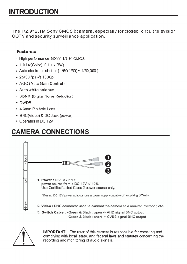
Power
General
Function
Connector
&
ETC
MODEL
Power Source
Power Consumption
Image Sensor
Total Pixels
Active Pixels
Scanning System
Sync. System
Video Frame Rate
Min. illumination
Video Output
Camera Control
S/N Ratio
Lens
Shutter AUTO, 1/60, FLK ~ 1/50,000 sec
AGC 1 ~ 15
Sens-UP OFF / AUTO (x2, x4, x6, x8, x10, x15, x20, x25, x30)
Exposure
Brightness 1 ~ 100
D-WDR OFF / ON / AUTO
Defog OFF / AUTO
Backlight
White Balance
Day & Night
2DNR OFF / LOW / MIDDLE / HIGH
DNR
3DNR OFF / LOW / MIDDLE / HIGH
Camera Title OFF / ON
D-Effect OFF / FREEZE / MIRROR / NEG.IMAGE
S
Motion Detection OFF / ON (4 zone)
P
Privacy Masking OFF / ON (4 zone)
E
Language
C
Defect Detection LIVE DPC / WHTE DPC / BLACK DPC
I
Sharpness OFF / AUTO (0 ~ 10)
A
Monitor CRT / LCD
L
LSC (Shading) OFF / ON
Video mode NTSC / PAL
Save & Exit
Power input
Video output
Transmission Distance
Lens mount
Lens
Operating temperature
Operating humidity
External dimension
Weight
ENG / CHN1 / CHN2 / GER / FRA / ITA / S PA / POL / RUS / P OR / NED / TUR / KOR / JPN / HEB / ARB
Height Strip Covert Camera
DC12V ± 10%
Max 2.2 Watts (180mA)
1/2.9" 2.1M Sony CMOS
2000(H) x 1121(V)
1920(H) x 1080(V)
1920×1080p@25 fps;1920×1080p@30 fps
1.0 lux(COLOR), 0.1 Lux(B/W)
BNC (AHD / CVBS Selectable)
OSD Menu (Coaxial control)
More than 50dB (AGC off)
OFF / BLC / HSBLC
ATW / AWC / INDOOR / OUTDOOR / AWB
AUTO / COLOR / B&W
SAVE & EXIT / NO SAVE / RESET
BNC Connector (AHD / CVBS)
Over 500m via 5C-2V coaxial cable
f=4.3mm F2.0 Megapixel Fixed Pin Hole Lens
14°F ~ 122°F (-10℃ ~ +50℃)
0 ~ 90% (non-condencing)
55.0mm x 872.6mm x 31.5 (44.45mm Inclusion bracket)
Unit : 1.36kg, Shipping : 2.0kg
Progressive
Internal
MANUAL
DC JACK
Fixed mount
Page 22

Height Strip Covert Camera
PRINTED IN KOREA
50304
267A
 Loading...