

Page 1
540TV Lines
ATV
FD540DNIR
S
uper High Resolution
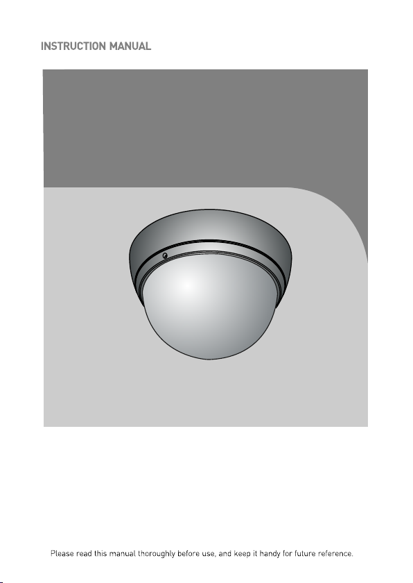
Infrared - LED Dome Camera
3-AXIS INFRARED - LED
PLASTIC DOME CAMERA
Page 2

LIMITATIO N OF L IA BI LI TY
THE INF ORM ATIO N IN TH IS PUBL ICAT ION I S BELIE VED TO BE ACC URAT E IN
ALL RESP ECTS, H OWE VER, WE C ANN OT ASS UME RES PON SIBIL ITY F OR ANY
CON SE QUE NCES RE SULT ING F ROM THE USE THERE OF. THE I NFO RMATION
CON TAINED H ERE IN IS SUB JEC T TO CHANG E WIT HOUT NOTIC E. RE VI SIO NS
OR NE W ED ITI ONS TO THI S PUB LICATION MAY BE I SSUED TO I NCORP ORAT E
SUCH CH ANG ES.
ii
Page 3
WARNINGS AND CAUTIONS:
TO REDUCE THE RISK OF FIRE OR ELECTRIC SHOCK, DO NOT EXPOSE THIS PRODUCT TO RAIN OR
MOISTURE. DO NOT INSERT ANY METALLIC OBJECTS THROUGH THE VENTILATION GRILLS OR
OTHER OPENINGS ON THE EQUIPMENT.
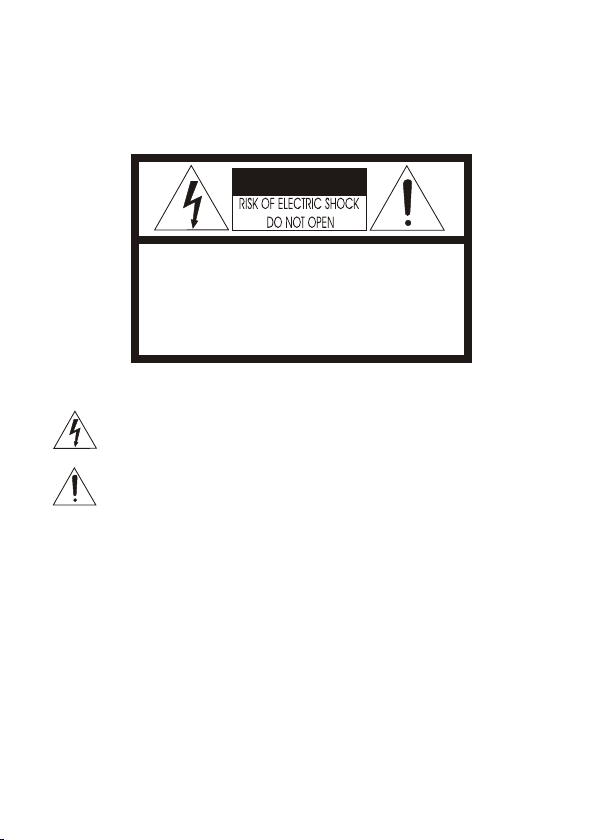
CAUTION:
CAUTIONCAUTION
CAUTION: TO REDUCE THE RISK OF ELECTRIC SHOCK,
DO NOT REMOVE COVER(OR BACK).
NO USER-SERVICEABLE PARTS INSIDE.
REFER SERVICING TO QUALIFIED SERVICE PERSONNEL.
EXPLANATION OF GRAPHICAL SYMBOLS
The lightning flash with arrowhead symbol, within an equilateral triangle, is
intended to alert the user to the presence of uninsulated "dangerous voltage"
within the product's enclosure that may be of sufficient magnitude to constitute a
risk of electric shock to persons.
The exclamation point within an equilateral triangle is intended to alert the user to
the presence of important operating and maintenance (servicing) instructions in the
literature accompanying the product.
PRECAUTIONS
Safety ----------------------------------------- Installation -----------------------------------
Should any liquid or solid object fall into the cabinet,
unplug the unit and have it checked by the qualified
personnel before operating it any further.
Unplug the unit from the wall oulet if it is not going to
be used for several days or more. To disconnect the
cord, pull it out by the plug. Never pull the cord itself.
Allow adequate air circulation to prevent internal heat
build-up. Do not place the unit on surfaces (rugs,
blankets, etc.) or near materials(curtains, draperies)
that may block the ventilation holes.
Height and vertical linearity controls located at the
rear panel are for special adjustments by qualified
personnel only.
Do not install the unit in an extremely hot or
humid place or in a place subject to excessive
dust, mechanical vibration.
The unit is not designed to be waterproof.
Exposure to rain or water may damage the unit.
Cleaning --------------------------------------
Clean the unit with a slightly damp soft cloth.
Use a mild household detergent. Never use
strong solvents such as thinner or benzine as
they might damage the finish of the unit.
Retain the original carton and packing
materials for safe transport of this unit in the
future.
iii
Page 4
FCC COMPLIANCE STATEMENT
FCC INFORMATION : THIS EQUIPMENT HAS BEEN TESTED
AND FOUND TO COMPLY WITH THE LIMITS FOR A CLASS A DIGITAL
DEVICE, PURSUANT TO PART 15 OF THE FCC RULES. THESE
LIMITS ARE DESIGNED TO PROVIDE REASONABLE PROTECTION
AGAINST HARMFUL INTERFERENCE WHEN THE EQUIPMENT IS
OPERATED IN A COMMERCIAL ENVIRONMENT. THIS EQUIPMENT
GENERATES, USES, AND CAN RADIATE RADIO FREQUENCY
ENERGY AND IF NOT INSTALLED AND USED IN ACCORDANCE WITH
THE INSTRUCTION MANUAL, MAY CAUSE HARMFUL INTERFERENCE
TO RADIO COMMUNICATIONS. OPERATION OF THIS EQUIPMENT IN
A RESIDENTIAL AREA IS LIKELY TO CAUSE HARMFUL
INTERFERENCE IN WHICH CASE THE USER WILL BE REQUIRED TO
CORRECT THE INTERFERENCE AT HIS OWN EXPENSE.
CAUTION : CHANGES OR MODIFICATIONS NOT EXPRESSLY
APPROVED BY THE PARTY RESPONSIBLE FOR COMPLIANCE
COULD VOID THE USER'S AUTHORITY TO OPERATE THE EQUIPMENT.
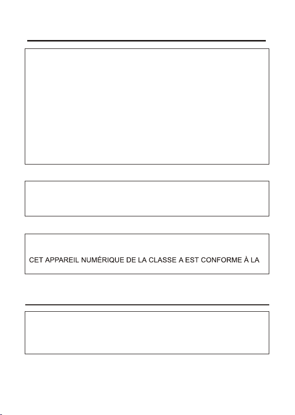
THIS CLASS A DIGITAL APPARATUS COMPLIES WITH CANADIAN
ICES-003.
NORME NMB-003 DU CANADA.
CE COMPLIANCE STATEMENT
WARNING
This is a Class A product. In a domestic environment this product
may cause radio interference in which case the user may be required
to take adequate measures.
iv
Page 5
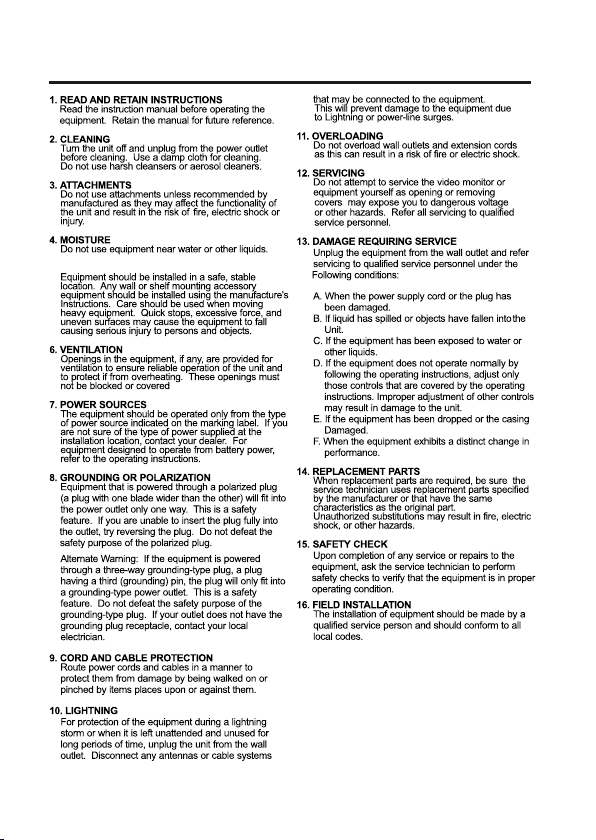
IMPORTANT SAFEGUARDS
5. ACCESSORIES
17. CAUTION-thes e servic ing instructions are
for use by qualified serv ice personnel only.
to reduce the risk of electric sh ock do not
perform any serv icing other than that contained
in the operatin g instructions unless yo u are
qual ified to do so.
7
1 -1 Class 2 power source only.
17
-2 Do NOT use power source other than that specified.
v
Page 6

TABLE OF CONTENTS
INTRODUCTION
CAMERA CONNECTION
BASIC CAMERA INSTALLATION
INSTALLING & ADJUSTING CAMERA MODULE
BASE INSTALLATION
STRUCTURE OF THE SETUP MENU
OPERATING CAMERA
LENS ADJUSTMENT
DC AUTO IRIS LENS
TROUBLESHOOTING AND MAINTENANCE
SPECIFICATIONS
EXTERNAL DIMENSION
1
2
3
4
5
7
8
18
18
19
20
21
vi
Page 7

INTRODUCTION
The camera provides high-quality images using SONY CCD technology especially
designed for closed-circuit television (CCTV) and security surveillance
applications.
Features:
High resolution and high performance 1/3" SONY Super HAD CCD
Technology
Excellent picture quality
540 lines(Color) of resolution
0.5 lux(Color), 0 lux(IR LED ON) @ F.1.2 Sensitivity
Auto electronic shutter [1/60(1/50) ~ 1/120,000] and manual electronic
shutter modes
OSD (On Screen Display)
DNR
(Digital Noise Reduction) Auto Function
Auto and manual white balance modes
BLC (Back Light Compensation)
Day&Night (Auto / DAY / NIGHT / EXT)
Privacy Zone 4point
AGC (Auto Gain Control)
Sense-up (x2 ~ x32)
MIRROR (NORMAL /MIRROR/VERTICAL /ROTATE)
VIDEO OUT(BNC)
Motion Detection
Internal / AC line lock
4-9mm Day/Night A/I Varifocal Lens F1.6~2.4
Operates in 12 VDC or 24 VAC
Use Certified / Listed Class 2 power supply only.
Camera Mount : camera mount directily to the wall or ceiling
Test Monitor Output
1
Page 8
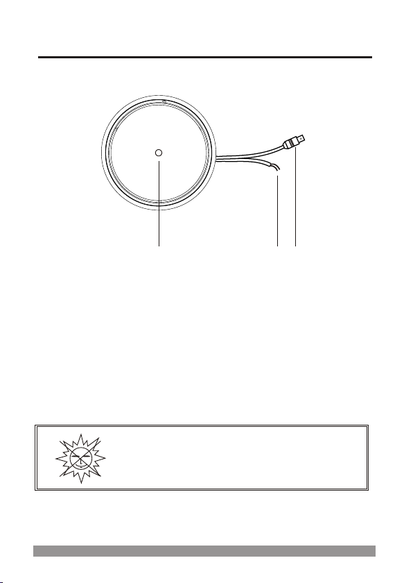
CAMERA CONNECTIONS
1
1. Lens : 4-9mm D&N A/I Vari-focal lens for wide area monitoring.
2. Power : 24V AC input / 12V DC input
power source from a DC 12V or AC 24V ac +/-10% 60/50Hz +/-1Hz
Use Certified/Listed Class 2 power supply transformer only.
*If using DC 12V power adaptor,
use a power supply capable of supplying 8 Watts.
3. Video : BNC connector used to connect the camera to a monitor, switcher, etc.
3
2
REMINDER:
Never aim the camera directly into the sun.
2
Page 9
BASIC CAMERA INSTALLATION
Unpack and identify the following parts from the product carton:
D. Anchor
Note : Make sure the power is turned off when connecting the power
adaptor cable.
TOP
Note : Arrow ma rk ind ic ates th e to p of the came ra i mage.
3
Page 10

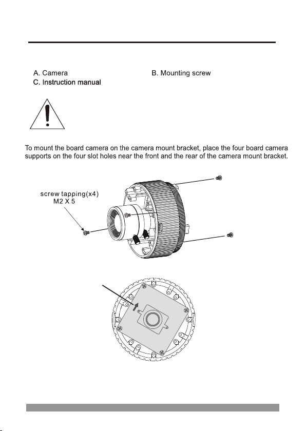
INSTALLING & ADJUSTING CAMERA MODULE
Use the following drawings to install the camera module to the housing.
Sen sor C ap
At ex tre me ti lt angles :
Use t his t o cover a sen sor i f it points insi de th e hou sin g.
1
80
3
60
36
0
3-A xis Cam era Con struc tion
Cam era len s can be mo ved
c r
IR a
e onl
m
a
y
Scre w Taptite (FC)
M3x6
hor izont ally or v ertic ally an d
fre ely swi veled t o any ang le.
Note: The distance between the camera and the target must exceed 0.5M
4
Page 11

BASE INSTALLATION
1
Make mounting holes and cable hole in the place (ceiling) to which
this dome camera is installed using the Drilling guide label.
Dome window
2
To remove dome cover, turn the dome cover counterclockwise
until locators reach end of travel and pull off.
5
Page 12

BASE INSTALLATION, continued
3
Fasten Mounting screws(2X) and align the dome camera
with it like above picture.
Turn the dome camera to left direction about 16 degree.
Drilling Guide Label
Plastic anchor
Special Screw (M4)
4
The assembly of the dome window cover is in reverse
order of disassembly.
Finally, lock dome window cover with locking screw(M2X4)
from the accessory kit.
6
Page 13

STRUCTURE OF THE SETUP MENU
EXPOSURE
WHITE BAL
DAY/NIGHT
MOTION
PRIVACY
OPTION
DISPLAY
SYNC
INITIAL
EXIT
-LENS
-BRIGHTNESS
-BACKLIGHT
-SHUTTER
-AGC
-SENSE UP
-WB MODE
-RED CONT
-BLUE CONT
-PUSH AUTO
-D/N MODE
-AUTO LEVEL
-FILTER DLY
-SENSOR IN
-DETECT MODE
-DETECT AREA
-SENSITIVITY
-ALARM TIME
-AREA
-MASK
-LEVEL
-TOP
-DOWN
-LEFT
-RIGHT
-TITLE
-NEGA/POSI
-SHARPNESS
-MIRROR
-ZOOM
-PAN/TILT
-PHASE
-TITLE
-MOTION DET
-DEFAULT
-USER
AREA
TITLE
POSITION
7
Page 14

OPERATING CAMERA
<SETTINGS>
Settings can be made using the 5 buttons located at the base of the camera.
1) [ENTER] ON or OFF of OSD MENU
2) [UP] / [DOWM] UP or DOWN of Cursor
3) [LEFT] / [RIGHT] SUB MENU ON or Decision
* When OSD MENU is OFF and PAN/TILT is ON, operate by [UP], [DOWN],
[LEFT], [RIGHT].
MOTION DETECT becomes invalid while moving PAN/TILT.
<MAIN MENU>
M ENU
▶
EXPOSURE
WHITE BAL
DAY/NIGHT
MOTION
PRIVACY
OPTION
DISPLAY
SYNC
INITIAL
EXIT
1) EXPOSURE, WHITE BAL, DAY/NIGHT, MOTION, PRIVACY, OPTION and
DISPLAY each have a SUB MENU and are selected using the [UP]/[DOWN]
buttons.
The SUB MENUS are displayed by [LEFT] / [RIGHT].
2) SYNC : AUTO or INT can be selected.
3) When making INITIAL from USER to DEFAULT, all data is initialized.
Selecting "Default" in the INITIAL menu, will reset to factory default settings.
*
When changes are made to the menu, "USER" will be displayed in the INITIAL menu.
*
+…
+…
+…
+…
+…
+…
+…
A U T O
D EF AU LT
4) To EXIT the menu use the [LEFT] / [RIGHT] buttons when EXIT is highlighted.
* To save the settings in the menu, press the [ENTER] button.
8
Page 15

<EXPOSURE>
Press the [LEFT] or [RIGHT] button to access the "EXPOSURE" mode.
EXPOSURE
▶
LENS
BRIGHTNESS
BACKLIGHT
SHUTTER
AGC
SENSE UP
RETURN
1) LENS DC or ELC can be selected.
2) BRIGHTNESS 0 to 60 can be selected.
3) BACKLIGHT ON or OFF can be selected.
[RIGHT] button.
Level setting is available in DC and ELC mode.
Prevents such a back light effect to secure a clear
image under all illumination environments.
4) SHUTTER 1/60(NT) or 1/50(PAL), FLC, 1/250, 1/500, 1/1000,
1/2000, 1/4000, 1/10000 can be selected.
) AGC AGC OFF, LOW, MID, HIGH can be selected.
5
6) SENSE UP OFF, x2, x4, x8, x16, x32 can be selected.
It becomes 1/60 at NTSC. It becomes 1/50 at PAL.
The level of noise also increases.
by automatically detecting change in the level of light
in low level conditions.
D C/E L C
~
0 60
ON/O F F
1/60 ( /50)
1
~ 1/ 1 0 0 0 0
OFF/ LO W / MI D / H I G H
OFF/x2 ~x 32
Adjust the brightness level by pressing the [LEFT] or
*
*
* It is NOT possible to select the shutter speeds when set to ELC.
As the level of gain increases, the screen gets brighter.
*
SENSE UP helps maintain a bright, clear screen image
*
7) RETURN Return to MAIN MENU.
9
Page 16

<WHITE BALANCE>
Press the [LEFT] or [RIGHT] button to access the "WHITE BALANCE" mode.
WHITE BAL
▶
WB MODE
RED CONT
BLUE CONT
PUSH AUTO
RETURN
1) WB MODE
- ATW This mode can be used within the colour temperature range
- AWC
- MANUAL
2.300°K ~ 10.500°K
Please press the [LEFT] or [RIGHT] button in the PUSH
AUTO mode while the camera is directed at a piece of
white paper to obtain the optimum state under current
illumination. If the environment including the light source is
changed, you have to adjust the White balance again.
Manual mode. User can change R and B Gain manually.
To adjust R and B Gain, press [LEFT] or [RIGHT] button
and use [UP] and [DOWN] button.
ATW / AWC / MANUAL
0~127
0~127
ON/OFF
2) RED CONT
3) BLUE CONT
4) PUSH AUTO
5) RETURN
When set to MANUAL, 0 to 127 can be selected.
Another becomes NOT USE.
When MANUAL, 0 to 127 can be selected.
set to
Another becomes NOT USE.
When AWC, OFF to PUSH can be selected.
set to
Another becomes NOT USE.
Return to MAIN MENU.
10
Page 17

<DAY/NIGHT>
Press the [LEFT] or [RIGHT] button to access the "DAY/NIGHT" mode.
DAY/NIGHT
▶
D/N MODE
AUTO LEVEL
FILTER DLY
SEN OR
S IN
RETURN
1) D/N MODE AUTO, DAY, NIGHT, EXT can be selected.
- AUTO
This camera has a function which automatically changes to
- DAY
- NIGHT
-
EXT
the COLOR mode or B/W mode by the internal IR sensor's
signal.
the appropriate mode for daytime or night-time.
The COLOR mode is operated for daytime,
and it converts to BW mode for night-time.
In this mode, the camera outputs the video image only in color.
In this mode, the camera outputs the video image only in
black and white.
In this mode, the camera outputs the video image change to
(IR camera default setting : EXT)
2) AUTO LEVEL When set to AUTO, the 0 to 18 values can be selected.
3) FILTER DLY When set to AUTO, 4 to 10 can be selected.
When AGC is OFF, NOT USED.
from on to off or off to on.
)
4 W hen D/N MODE is EXT, NO or NC can be selected.
SENSOR IN
* It changes by setting AGC.
AGC OFF: NOT USE
AGC LOW: 0 to 3can be selected.
AGC MID:
AGC HIGH: 0 to 18can be selected.
* Adjust the delay time of filter movement when changing
When D/N MODE is another (AUTO, DAY, NIGHT),
NOT USE is displayed.
5) RETURN Return to MAIN MENU.
AUTO/DAY/NIGHT/EXT
0~18
4~10 SEC
NOT USE / NO / NC
D.
0 to 11can be selected.
11
Page 18

<MOTION>
Press the [LEFT] or [RIGHT] button to access th "MOTION"mode.
MOTION
▶
DETECT MODE
DETECT AREA
SENSITIVITY
ALARM TIME
RETURN
ON/OFF
+…
0~8
1~60 SEC
1) DETECT MODE ON or OFF can be selected.
* Turning on be comes inval id while dis playing OSD .
Howeve r, it becomes e ffective only at MOTI ON AREA.
2) DETECT AREA MOTION AREA is displayed.
3) SENSITIVITY 0 to 8 can be selected.
4) ALARM TIME 1 to 60 sec can be selected.
5) RETURN
Return to MAIN MENU.
12
Page 19

<MOTION AREA>
cursor
] ]
inactive
active
]
]
Press the [LEFT or [RIGHT button to access the "MOTION AREA" mode.
- A thick gray shows the cursor.
- When it is transparent, the area becomes active.
* Default is ALL transparent, it is ALL active.
- When it is light gray, the area becomes inactivity.
- Cursor moved by [LEFT or [RIGH .
- [
When UP] or [ DOWN] is pushed, it becomes active or inactive.
[ ]
- MENU is returns to the MOTION.
NOTE :
BLC automatically becomes effective on this screen.
13
Page 20

<PRIVACY>
Press the [LEFT] or [RIGHT] button to access the "PRIVACY" mode.
PRIVACY
▶
AREA
MASK
LEVEL
TOP
DOWN
LEFT
RIGHT
RETURN
1) AREA 1 to 4 can be selected.
2) MASK ON or OFF can be selected.
3) LEVEL When MASK is ON, 0 to 15 can be selected.
4) TOP When MASK is ON, 3 to 124(NTSC) or 6 to 150(PAL) can
be selected.
5) DOWN When MASK is ON, 5 to 126(NTSC) or 8 to 152(PAL) can
be selected.
6) LEFT When MASK is ON, 0 to 187(NTSC) or 0 to 185(PAL) can
be selected.
7) RIGHT When MASK is ON, 2 to 189(NTSC) or 2 to 187(PAL) can
be selected.
*It set the same value regardless of a set value of the AREA size.
8) RETURN Return to MAIN MENU.
1~4
ON/OFF
0~15
3~124/ 6~150
5~126/ 8~152
0~187/ 0~185
2~189/ 2~187
14
Page 21

<OPTION>
Press the [LEFT] or [RIGHT] button to access the "OPTION" mode.
OPTION
▶
TITLE
POSI/NEGA
SHARPNESS
MIRROR
ZOOM
PAN/TILT
PHASE
RETURN
1) TITLE TITLE is displayed.
NEGA POSI NEGA
2) POSI/ or can be selected.
3) SHARPNESS 0 to 15 can be selected.
4) MIRROR
NORMAL, MIRROR, VERTICAL, ROTATE can
be selected.
- MIRROR Horizontal image inversion
- VERTICAL Vertical image inversion
- ROTATE Horizontal image and Vertical image inversion
5) ZOOM 0FF(x1) and ON1 to ON8(x4) can be selected.
When PAN/TILT is ON, it is NOT USE.
6) PAN/TILT OFF or ON(x2) can be selected.
operate by [UP],[DOWN],[LEFT],[RIGHT].
7) PHASE Sync phase is adjustable in line lock mode (Auto mode)
0 ~ 524 (NTSC) or 0 ~ 624 (PAL).
8) RETURN Return to MAIN MENU
+…
POSI/NEGA
0~15
NORMAL/MIRROR/VERTICAL/ROTATE
OFF/ON1~ON8
ON/OFF
0 ~ 524 / 0 ~ 624
* When OSD MENU is OFF and PAN/TILT is ON,
NOTE :
- When the power frequency is 50Hz, you can not use line-lock mode (NTSC Models).
- When the power frequency is 60Hz, you can not use line-lock mode (PAL Models).
1215
Page 22

<TITLE>
Press the [LEFT] or [RIGHT] button to access the "TITLE" mode.
TITLE
BS
POS
+ - ~
uvwxyz
s t
! % ( ) "
#
&
END
m
l
; .
_
TITLE MENU.
ABCDEFGH I J KLM
NOPQRSTUVWXYZ
abcdefgh i j k
nopqr
012 3456 78 9 :
* /
1) TITLE It moves by[UP], [DOWN], [LEFT] and [RIGHT].
Characters are set by pressing [ENTER]. The character from
1 to 10 can also be set.
- ← Move to the left, When [ENTER] button is pushed by ←
- → Move to the left, When [ENTER] button is pushed by →
- BS Erase the character
- POS Change the position of the title
title by using 4 directional buttons, and then press the [ENTER]
button.)
- END
(If you want to change the position of the title, press [ENTER]
button at the "POS". Find the position you wish to display the
*one or more characters have to be set for a position change
to occur.
When [ENTER] is pushed by “END”, return to the
16
Page 23

<DISPLAY>
Press the [LEFT] or [RIGHT] button to access the "DISPLAY" mode.
DISPLAY
▶
TITLE
MOTION DET
ON/OFF
ON/OFF
RETURN
1) TITLE ON or OFF can be selected.
2) MOTION DET ON or OFF can be selected.
3) RETURN Return to MAIN MENU.
- Video out check-
ENTER
L
E
FT
R
I
G
H
T
Tact s witch b oard
D NOW
P
U
Test M oni tor
Vid eo out Ca ble
17
Page 24

LENS ADJUSTMENT (OPTIONAL VARIFOCAL LENS)
Field of view: Adjust setting from Tele (T)
to Wide (W) field of View.
Focus: Adjust lens focus from near
(N) to infinity ( ).
DC AUTO IRIS LENS
Image Size 1/3" CCD
Focal Length
Aperture Ratio
Angular
Field of View
LENS
T
W
4-9mm
4.0-9.0mm 5%
1 : 1.6 5%
DIAGONAL
4mm : 92.4
9mm : 39.2
White Control ( + )
Black Control ( - )
Red Drive ( + )
Green Drive ( - )
o
o
N
Adjust Focus
Adjust Angular Field View
18
Page 25

TROUBLESHOOTING
If you experience difficulties operating your camera, refer to the following. If the
guidelines do not enable you to solve the problem, contact an authorized
technician.
PROBLEM
Nothing appears on
the screen.
The image on the screen
is dim.
The contrast on the
screen is too weak.
The image on the screen
flickers.
Is the cable connected between the
camera and monitor?
Is there power to the monitor?
Is the lens dirty? If so, clean the lens
with a soft, clean cloth.
Adjust the contrast feature of the monitor.
Is the camera exposed to strong light?
If so, change the camera position.
Does the camera face directly into the
sun or fluorescent lighting?
If so, reposition camera.
CHECK
PREVENTIVE MAINTENANCE
Following the preventive maintenance schedule allows detection and correction
of minor faults before they become serious and cause equipment failure.
Every three months, perform the following:
1. Inspect all connecting cables for deterioration or other damage.
2. Clean components with a clean damp cloth.
3. Verify that all the mounting hardware is secure.
19
Page 26

SPECIFICATIONS
Power
General
IR
Function
Connecto r
&
etc.
MODEL
Power sour ce
Power cons umption
Image sens or
Total number of pix els
Scanning s ystem
Scanning f requency
Sync. syst em
Electron ic shutter
Resoluti on
Min. illum ination
Video outp ut
S/N ratio
Function C ontrol
DNR Funcio n
IR LED
IR Waveleng ht
IR distanc e range
IR project a ngle
IR ON/OFF
Auto Expos ure
Lens(Aut o Iris Control)
Brightne ss
BLC
AGC
Sense-up
White Bala nce
Day & Night
Motion det ection
Privacy zo ne
Display Titl e
Video Pict ure
Sharpnes s
Mirror
Zoom
Pan& Tilt
Sync
Preset
Power inp ut
Video out put
Lens mount
Lens
Operatin g Temperatur e
Operatin g humidity
NTSC
3.5 Watts / 6.0 Watts (IR ON)
1/3" SONY Super-HAD CCD
811(H) x 508(V)
15.734KHz(H) x 59.94Hz(V)
1/60 ~ 1/120,000 sec.
25m~30m (from object of view reflected infrared)
1/50(1/60) / FLICKERLESS / MANUAL SHUTTER
(When OSD Menu is OFF & PAN/TILT is ON.)
Day/Night A/I Varifocal 4~9mm Lens, F1.6~2.4
(Day/Night A/I Varifocal 2.6~6mm Lens is optional)
2:1 interlace
Internal / Line Lock
540 TV Lines
0.5 lux(Color), 0 lux (IR LED ON) @ F1.2, 50 IRE
1.0 Vp-p (75 ohm, composite)
More then 50dB (AGC off)
TACT Switch
23 pcs high br ightness IR LED
850nm
40 degree
Light Sensor Control
(1/250, 1/500, 1/1000, 1/2000, 1/4000, 1/10000)
OFF / ON (Sensitivity & Alarm time Selective)
NORMAL / MIRROR / VERTICAL / ROTATE
DC / ELC
0 ~ 60
ON / OFF
OFF / LOW / MIDDLE / HIGH
OFF / x2 /x4 / x8 / x16 / x32
ATW / AWC / MANUAL
AUTO / DAY / NIGHT / EXT
(IR Camera default setting : EXT)
OFF / ON (4 point)
OFF / ON
POSI / NEGA
0 ~ 15
OFF(x1) / ON1 ~ ON8(x4)
(When PAN/TILT is ON, it is NOT USE.)
OFF / ON(x2)
INT / AUTO
INITIAL / EXIT(Auto save) / RETURN
2-Pin wire
BNC connector
Fixed Mount
o o o o
-10 C ~ 50 C [14 F ~ 122 F
0 ~ 96% (non-condencing)
PAL
795(H) x 596(V)
15.625KHz(H) x 50Hz(V)
1/50 ~ 1/120,000 sec.
ON
]
20
Page 27

EXTERNAL DIMENSION
Dimensions
120
Maximum Camera and
Lens Size
Window Size
Cable Entry
Weight - Unit:
Shipping:
87.9
32.9
100 (Inner)
Uni t: mm
2.6L x 1.65W x 1.65H in.
(6.5L x 4.2W x 4.2H cm)
0.1 in. (2.5mm thick),
impact-resistant P.C (LEXAN)
3.93 in. (10.0cm) diameter
Two 0.3"(0.8cm)and one 0.5"(1.3cm)
opening holes.
0.61 lb. (0.28 kg)
0.82 lb. (0.37 kg)
21
Page 28

540TV Lines Super High Resolution
Infrared - LED Dome Camera
50302297C
 Loading...