

ATV FA4-120 User Manual


User’s Manual
ii
Four-Channel Digital Video Recorder
WARNING
RISK OF ELECTRIC SHOCK
DO NOT OPEN
WARNING: TO REDUCE THE RISK OF ELECTRIC SHOCK,
DO NOT REMOVE COVER (OR BACK).
NO USER-SERVICEABLE PARTS INSIDE.
REFER SERVICING TO QUALIFIED
SERVICE PERSONNEL.
The lightning flash with arrowhead symbol, within an equilateral triangle, is intended to
alert the user to the presence of uninsulated "dangerous voltage" within the product's
enclosure that may be of sufficient magnitude to constitute a risk of electric shock.
The exclamation point within an equilateral triangle is intended to alert the user to the
presence of important operating and maintenance (servicing) instructions in the literature
accompanying the appliance.
COMPLIANCE NOTICE OF FCC:
THIS EQUIPMENT HAS BEEN TESTED AND FOUND TO COMPLY WITH THE LIMITS FOR A CLASS A
DIGITAL DEVICE, PURSUANT TO PART 15 OF THE FCC RULES. THESE LIMITS ARE DESIGNED TO
PROVIDE REASONABLE PROTECTION AGAINST HARMFUL INTERFERENCE WHEN THE EQUIPMENT
IS OPERATED IN A COMMERCIAL ENVIRONMENT. THIS EQUIPMENT GENERATES, USES, AND CAN
RADIATE RADIO FREQUENCY ENERGY AND IF NOT INSTALLED AND USED IN ACCORDANCE WITH
THE INSTRUCTION MANUAL, MAY CAUSE HARMFUL INTERFERENCE TO RADIO COMMUNICATIONS.
OPERATION OF THIS EQUIPMENT IN A RESIDENTIAL AREA IS LIKELY TO CAUSE HARMFUL
INTERFERENCE, IN WHICH CASE USERS WILL BE REQUIRED TO CORRECT THE INTERFERENCE AT
THEIR OWN EXPENSE.
WARNING: CHANGES OR MODIFICATIONS NOT EXPRESSLY APPROVED BY THE PARTY
RESPONSIBLE FOR COMPLIANCE COULD VOID THE USER’S AUTHORITY TO OPERATE THE
EQUIPMENT.
THIS CLASS OF DIGITAL APPARATUS MEETS ALL REQUIREMENTS OF THE CANADIAN
INTERFERENCE-CAUSING EQUIPMENT REGULATIONS.
The information in this manual is believed to be accurate as of the date of publication. ATV
any problems resulting from the use thereof. The information contained herein is subject to change without notice.
Revisions or new editions to this publication may be issued to incorporate such changes.
®
is not responsible for
iii

User’s Manual
Important Safeguards
1. Read Instructions
All the safety and operating instructions should be read before the
appliance is operated.
2. Retain Instructions
The safety and operating instructions should be retained for future
reference.
3. Cleaning
Unplug this equipment from the wall outlet before cleaning it. Do not
use liquid aerosol cleaners. Use a damp soft cloth for cleaning.
4. Attachments
Never add any attachments and/or equipment without the approval of
the manufacturer as such additions may result in the risk of fire,
electric shock or other personal injury.
5. Water and/or Moisture
Do not use this equipment near water or in contact with water.
6. Accessories
Do not place this equipment on an unstable cart, stand or table. The
equipment may fall, causing serious injury to a child or adult, and
serious damage to the equipment. Wall or shelf mounting should
follow the manufacturer's instructions, and should use a mounting kit
approved by the manufacturer.
This equipment and cart combination should be moved with care.
Quick stops, excessive force, and uneven surfaces may cause the
equipment and cart combination to overturn.
7. Power Sources
This equipment should be operated only from the type of power
source indicated on the marking label. If you are not sure of the type
of power, please consult your equipment dealer or local power
company.
8. Power Cords
Operator or installer must remove power and TNT connections before
handling the equipment.
9. Lightning
For added protection for this equipment during a lightning storm, or
when it is left unattended and unused for long periods of time, unplug
it from the wall outlet and disconnect the antenna or cable system.
This will prevent damage to the equipment due to lightning and
power-line surges.
10. Overloading
Do not overload wall outlets and extension cords as this can result in
the risk of fire or electric shock.
11. Objects and Liquids
Never push objects of any kind through openings of this equipment as
they may touch dangerous voltage points or short out parts that could
result in a fire or electric shock. Never spill liquid of any kind on the
equipment.
12. Servicing
Do not attempt to service this equipment yourself. Refer all servicing
to qualified service personnel.
13. Damage requiring Service
Unplug this equipment from the wall outlet and refer servicing to
qualified service personnel under the following conditions:
A. When the power-supply cord or the plug has been damaged.
B. If liquid is spilled, or objects have fallen into the equipment.
C. If the equipment has been exposed to rain or water.
D. If the equipment does not operate normally by following the
operating instructions, adjust only those controls that are covered
by the operating instructions as an improper adjustment of other
controls may result in damage and will often require extensive
work by a qualified technician to restore the equipment to its
normal operation.
E. If the equipment has been dropped, or the cabinet damaged.
F. When the equipment exhibits a distinct change in performance —
this indicates a need for service.
14. Replacement Parts
When replacement parts are required, be sure the service technician
has used replacement parts specified by the manufacturer or that have
the same characteristics as the original part. Unauthorized
substitutions may result in fire, electric shock or other hazards.
15. Safety Check
Upon completion of any service or repairs to this equipment, ask the
service technician to perform safety checks to determine that the
equipment is in proper operating condition.
16. Field Installation
This installation should be made by a qualified service person and
should conform to all local codes.
17. Correct Batteries
Warning: Risk of explosion if battery is replaced by an incorrect type.
Dispose of used batteries according to the instructions.
18. Tmra
A manufacturer’s maximum recommended ambient temperature
(Tmra) for the equipment must be specified so that the customer and
installer may determine a suitable maximum operating environment
for the equipment.
19. Elevated Operating Ambient Temperature
If installed in a closed or multi-unit rack assembly, the operating
ambient temperature of the rack environment may be greater than
room ambient. Therefore, consideration should be given to installing
the equipment in an environment compatible with the manufacturer’s
maximum rated ambient temperature (Tmra).
20. Reduced Air Flow
Installation of the equipment in the rack should be such that the
amount of airflow required for safe operation of the equipment is not
compromised.
21. Mechanical Loading
Mounting of the equipment in the rack should be such that a
hazardous condition is not caused by uneven mechanical loading.
22. Circuit Overloading
Consideration should be given to connection of the equipment to
supply circuit and the effect that overloading of circuits might have
on over current protection and supply wiring. Appropriate
consideration of equipment nameplate ratings should be used when
addressing this concern.
23. Reliable Earthing (Grounding)
Reliable grounding of rack mounted equipment should be maintained.
Particular attention should be given to supply connections other than
direct connections to the branch circuit (e.g., use of power strips).
iv

Four-Channel Digital Video Recorder
Table of Contents
Chapter 1 — Introduction ..................................................................................1
Features ...........................................................................................................1
Technical Overview.........................................................................................2
Chapter 2 — Installation ....................................................................................3
Package Contents...........................................................................................3
Required Installation Tools............................................................................3
Connecting the Video Source........................................................................3
Connecting the Loop Through Video............................................................4
Connecting Audio ...........................................................................................4
Setting Unit for CVBS(SVHS) or VGA output ............................................... 4
Connecting the Monitor.................................................................................. 5
Connecting the Spot Monitor .........................................................................5
Connecting the RGB Monitor.........................................................................5
Connecting to the Network Port .................................................................... 6
Connecting to the RS-232C Port ...................................................................6
Factory Reset ..................................................................................................6
Connecting Alarms .........................................................................................7
AI 1 to 4 (Alarm In)......................................................................................... 7
GND (Ground)................................................................................................7
ARI (Alarm Reset In)......................................................................................7
Alarm Out.......................................................................................................8
Connecting to the RS-485 Port ...................................................................... 8
Connecting to the USB Port...........................................................................8
Connecting the Power Cord...........................................................................9
Chapter 3 — Configuration..............................................................................11
Front Panel Controls.....................................................................................11
Power LED...................................................................................................11
Alarm LED....................................................................................................11
REC LED .....................................................................................................11
Network LED................................................................................................11
Copy LED.....................................................................................................12
Camera Buttons (1 to 4) ..............................................................................12
QUAD/SEQ Button.......................................................................................12
PTZ Button...................................................................................................12
PANIC Button...............................................................................................12
Menu Button.................................................................................................12
Enter/Pause Button...................................................................................... 13
Arrow Buttons ..............................................................................................13
Shuttle Ring .................................................................................................13
Jog Dial ........................................................................................................13
v

User’s Manual
Turning on the Power ...................................................................................14
Initial Unit Setup............................................................................................14
Quick Setup Screen ......................................................................................14
Normal Setup Screen....................................................................................16
System Information ......................................................................................16
Date/Time Setup ..........................................................................................19
System Check Screen .................................................................................21
Storage Screen............................................................................................22
System Log Screen......................................................................................24
System Shutdown ........................................................................................24
Configuring Input Devices ...........................................................................25
Camera Setup Screen .................................................................................25
Alarm In Setup Screen.................................................................................26
Motion Detector............................................................................................27
Text-In Setup Screen ...................................................................................28
Alarm Out Setup Screen..............................................................................29
Audio Setup Screen.....................................................................................30
RS232/RS485 Setup Screen .......................................................................31
Configuring Recording Settings..................................................................32
Record Mode Setup Screen ........................................................................32
Time-Lapse Record Mode Setup Screen ....................................................33
Time-Lapse Recording Schedule ................................................................34
Pre-Event Recording Setup Screen.............................................................35
Event Action Setup .......................................................................................36
Alarm In Event Action (Record) Setup Screen ............................................36
Alarm In Event Action (Alarm Out) Setup Screen........................................37
Alarm In Event Action (Notify) Setup Screen...............................................37
Motion Detector Event Action (Record) Setup Screen ................................38
Motion Detector Event Action (Alarm Out) Setup Screen............................39
Motion Detector Event Action (Notify) Setup Screen...................................39
Text-In Event Action (Record) Setup Screen ..............................................40
Text-In Event Action (Alarm Out) Setup Screen..........................................41
Text-In Event Action (Notify) Setup Screen.................................................41
Video Loss Event Action (Record) Setup Screen........................................42
Video Loss Event Action (Alarm Out) Setup Screen ...................................43
Video Loss Event Action (Notify) Setup Screen ..........................................43
Display Setup ................................................................................................44
OSD (On-Screen Display) Setup.................................................................44
Main Monitoring Setup Screen ....................................................................45
Network Setup Screen..................................................................................46
LAN Setup Screen .......................................................................................47
Modem Setup...............................................................................................48
Callback Center Setup Screen ....................................................................49
Password Setup Screen ...............................................................................50
vi

Four-Channel Digital Video Recorder
Config Screen................................................................................................51
Clip Copy .....................................................................................................51
Load Default Setup ......................................................................................53
Clear All Data...............................................................................................53
Chapter 4 — Operation ....................................................................................55
Turning on the Power ...................................................................................55
Live Monitoring .............................................................................................55
PTZ Mode ....................................................................................................56
Digital Zoom Mode.......................................................................................57
Recording Video............................................................................................57
Recording Audio ...........................................................................................58
Playing Recorded Video...............................................................................58
Arrow Buttons ..............................................................................................58
Enter Button .................................................................................................59
Camera Buttons (1 to 4) ..............................................................................59
QUAD/SEQ Button.......................................................................................59
Shuttle Ring .................................................................................................59
Jog Dial ........................................................................................................59
Digital Zoom Playback Mode .......................................................................60
Searching Video ............................................................................................ 61
Date/Time Search ........................................................................................61
Calendar Search ..........................................................................................62
Event Search ...............................................................................................62
Appendix A — USB Hard Disk Drive Preparation .........................................65
Preparing the USB-IDE hard disk drive in Windows 2000 ........................65
Preparing the USB-IDE hard disk drive in Windows 98 ............................65
Appendix B — Troubleshooting .....................................................................67
Appendix C — Connector Pin Outs................................................................68
I/O Connector Pin Outs.................................................................................68
RS485 Connector Pin Outs ..........................................................................68
Appendix D — Map of Screens .......................................................................69
Appendix E — Specifications..........................................................................70
vii

User’s Manual
List of Illustrations
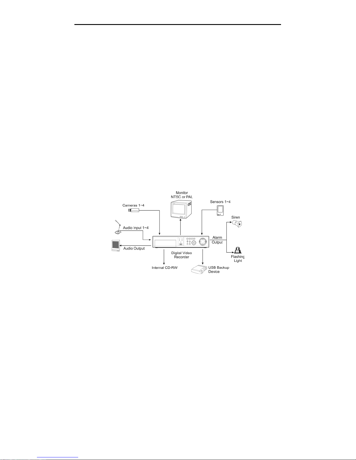
Figure 1 — Typical DVR installation. .......................................................................................... 1
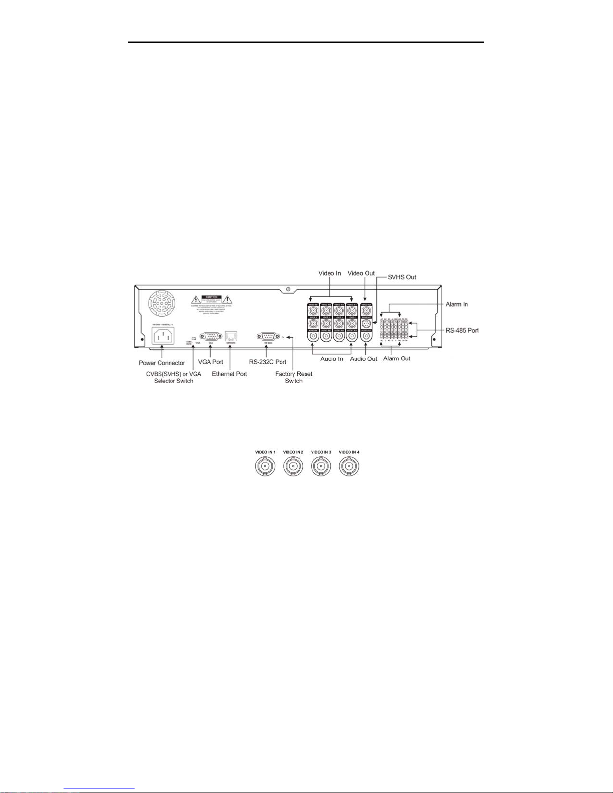
Figure 2 — DVR rear panel. .......................................................................................................3
Figure 3 — Video input connectors. ...........................................................................................3
Figure 4 — Video Loop Through connectors.............................................................................. 4
Figure 5 — Audio In and Out connectors. ..................................................................................4
Figure 6 — CVBS(SVHS)/VGA switch. ......................................................................................4
Figure 7 — Video Out connectors. .............................................................................................5
Figure 8 — VGA connector......................................................................................................... 5
Figure 9 — Network connector. .................................................................................................. 6
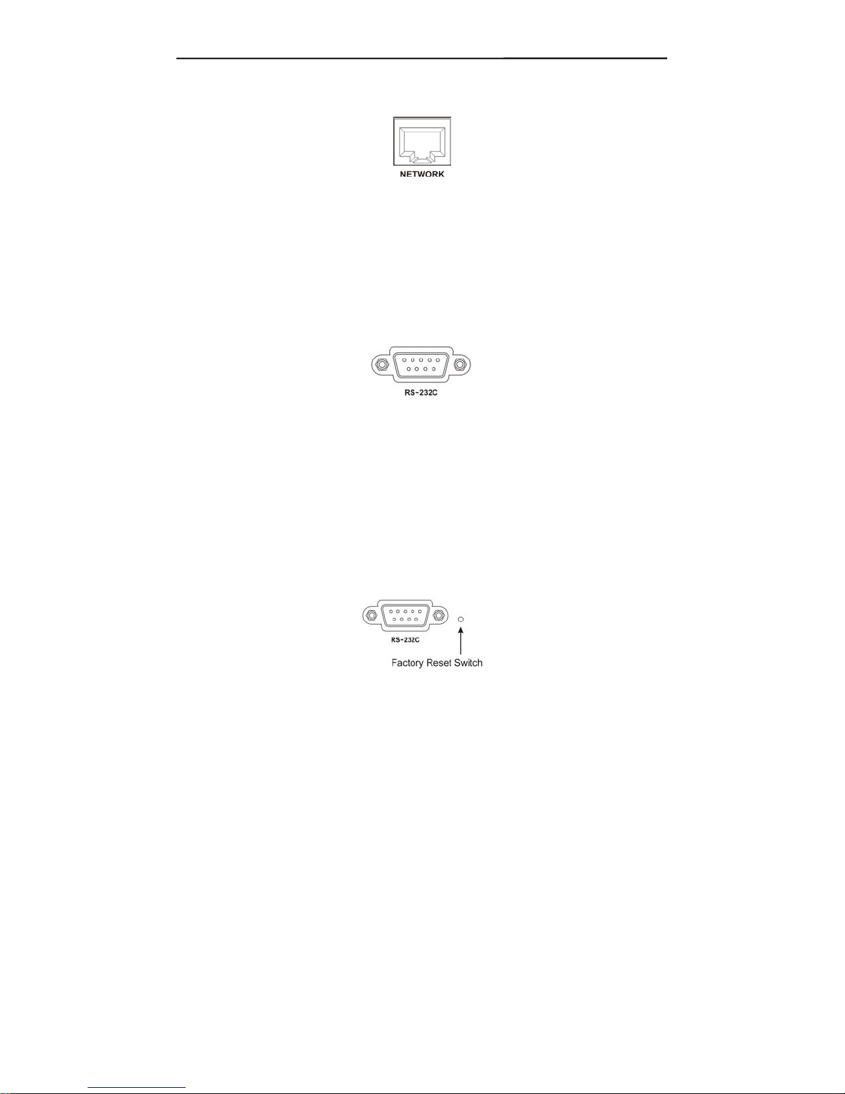
Figure 10 — RS-232C connector. ..............................................................................................6
Figure 11 — Factory reset switch. .............................................................................................. 6
Figure 12 — Alarm Input connector strips. .................................................................................7
Figure 13 — Alarm Output connector strips. ..............................................................................8
Figure 14 — RS-485 Connector. ................................................................................................ 8
Figure 15 — USB connector.......................................................................................................8
Figure 16 — Power cord connector............................................................................................ 9
Figure 17 — DVR front panel....................................................................................................11
Figure 18 — Admin Password screen. .....................................................................................14
Figure 19 — Quick Setup screen.............................................................................................. 14
Figure 20 — Normal Setup screen. ..........................................................................................16
Figure 21 — System Information screen. ................................................................................. 16
Figure 22 — System Information Change screen. ...................................................................17
Figure 23 — Virtual keyboard. .................................................................................................. 17
Figure 24 — System Upgrade screen. .....................................................................................18
Figure 25 — Date/Time setup screen....................................................................................... 19
Figure 26 — Holiday Setup screen........................................................................................... 20
Figure 27 — System Check screen.......................................................................................... 21
Figure 28 — Storage screen.....................................................................................................22
Figure 29 — S.M.A.R.T. Alert setup screen. ............................................................................23
Figure 30 — System Log screen. .............................................................................................24
Figure 31 — Device menu screen. ...........................................................................................25
Figure 32 — Camera setup screen...........................................................................................25
Figure 33 — PTZ Device list. ....................................................................................................26
Figure 34 — Alarm In setup screen. ......................................................................................... 26
Figure 35 — Motion Detector setup screen..............................................................................27
Figure 36 — Motion Detection Zone screen.............................................................................27
Figure 37 — Text-In Setup screen............................................................................................28
Figure 38 — Alarm Out setup screen. ......................................................................................29
Figure 39 — Alarm Out Schedule screen................................................................................. 30
Figure 40 — Audio Setup screen.............................................................................................. 30
Figure 41 — RS232/RS485 setup screen. ...............................................................................31
Figure 42 — Record Mode Setup screen. ................................................................................ 32
Figure 43 — Time-Lapse Record Setup screen....................................................................... 33
Figure 44 — Time-Lapse Recording Schedule screen.............................................................34
Figure 45 — Pre-Event Record Setup screen. ......................................................................... 35
Figure 46 — Alarm In Event Action (Record) setup screen......................................................36
Figure 47 — Alarm In Event Action (Alarm Out) setup screen.................................................37
Figure 48 — Alarm In Event Action (Notify) setup screen........................................................37
Figure 49 — Motion Detector Event Action (Record) setup screen. ........................................38
viii

Four-Channel Digital Video Recorder
Figure 50 — Motion Detector Event Action (Alarm Out) setup screen..................................... 39
Figure 51 — Motion Detector Event Action (Notify) setup screen............................................ 39
Figure 52 — Text-In Event Action (Record) setup screen........................................................40
Figure 53 — Text-In Event Action (Alarm Out) setup screen. .................................................. 41
Figure 54 — Text-In Event Action (Notify) setup screen. ......................................................... 41
Figure 55 — Video Loss Event Action (Record) setup screen................................................. 42
Figure 56 — Video Loss Event Action (Alarm Out) setup screen. ...........................................43
Figure 57 — Video Loss Event Action (Notify) setup screen. ..................................................43
Figure 58 — OSD Setup screen. .............................................................................................. 44
Figure 59 — Main Monitoring Setup screen. ............................................................................ 45
Figure 60 — Network Setup screen..........................................................................................46
Figure 61 — LAN Setup screen................................................................................................47
Figure 62 — Modem Setup screen........................................................................................... 48
Figure 63 — Callback Center Setup screen. ............................................................................ 49
Figure 64 — Password setup screen........................................................................................50
Figure 65 — Config screen.......................................................................................................51
Figure 66 — Clip Copy screen.................................................................................................. 52
Figure 67 — PTZ Menu. ...........................................................................................................56
Figure 68 — PTZ Preset screen. .............................................................................................. 56
Figure 69 — Preset view screen...............................................................................................57
Figure 70 — Playback (Text-In) screen.................................................................................... 58
Figure 71 — Digital Zoom screen. ............................................................................................ 60
Figure 72 — Enlarged Digital Zoom screen..............................................................................60
Figure 73 — Search Menu........................................................................................................ 61
Figure 74 — Date/Time Search screen. ................................................................................... 61
Figure 75 — Calendar Search screen. ..................................................................................... 62
Figure 76 — Event Log screen. ................................................................................................ 62
Figure 77 — Event Search (by Event) screen. ......................................................................... 63
Figure 78 — Event Search (by Camera) screen. .....................................................................63
ix

User’s Manual
x
Four-Channel Digital Video Recorder
Chapter 1 — Introduction
Features
Your color digital video recorder (DVR) provides recording capabilities for 4 camera inputs. It
provides exceptional picture quality in both live and playback modes, and offers the following
features:
• 4 Composite Input Connectors
• Auto detectable for NTSC or PAL
• Compatible with Color (NTSC or PAL) and B&W (CCIR and EIA-170) Video Sources
• Multiple Search Engines (Date/Time, Calendar, Event)
• Records up to 120 NTSC Images per Second (100 PAL Images per Second)
• “Loop-Through” Video Connectors
• Continuous Recording in Disk Overwrite Mode
• Continues Recording while Archiving, Transmitting to Remote Site and during Playback
• User-friendly Graphical User Interface (GUI) Menu System
• Various Record Modes (Time, Event, Pre-event and Panic)
• Audio Recording and Playback
• Alarm Connections Include: Input, Output and Reset Input
• Built-in Alarm Buzzer
• Live or Recorded Video Access via Ethernet or Modem
Figure 1 — Typical DVR installation.
1

User’s Manual
Technical Overview
Your DVR can replace both a time-lapse VCR and a multiplexer in a security installation.
However, it has many features that make it much more powerful and easier to use than even the
most advanced VCR.
The DVR converts analog NTSC or PAL video to digital images and records them on a hard disk
drive. Using a hard disk drive allows you to access recorded video almost instantaneously; there is
no need to rewind tape. The technology also allows you to view recorded video while the DVR
continues recording video.
Digitally recorded video has several advantages over analog video recorded on tape. There is no
need to adjust tracking. You can freeze frames, fast forward, fast reverse, slow forward and slow
reverse without image streaking or tearing. Digital video can be indexed by time or events, and you
can instantly view video after selecting the time or event.
Your DVR can be set up for event or time-lapse recording. You can define times to record, and the
schedule can change for different days of the week and user defined holidays.
The DVR can be set up to alert you when the hard disk drive is full, or it can be set up to record over
the oldest video once the disk is full.
Your DVR uses a proprietary encryption scheme making it nearly impossible to alter video.
You can view live video, search image, and control your DVR remotely by connecting via external
modem or Ethernet. There is a USB port that can used to back up the clip file video to USB-IDE
hard disk drives, USB CD-RW drives or flash drives.
2
Four-Channel Digital Video Recorder
Chapter 2 — Installation
Package Contents
The package contains the following:
• Digital Video Recorder
• Power Cord
• User’s Manual (This Document)
• RAS Software Diskettes and User’s Manual
• Assembly Screws for Adding Hard Disk Drives
Required Installation Tools
No special tools are required to install the DVR. Refer to the installation manuals for the other
items that make up part of your system.
Figure 2 — DVR rear panel.
Connecting the Video Source
Figure 3 — Video input connectors.
Connect the coaxial cables from the video sources to the BNC Video In connectors.
3

User’s Manual
Connecting the Loop Through Video
Figure 4 — Video Loop Through connectors.
If you would like to connect your video source to another device, you can use the Loop BNC
connectors.
NOTE: The Loop BNC connectors are auto terminated. Do NOT connect a cable to the Loop
BNC unless it is connected to another terminated device because it will cause poor quality
video.
Connecting Audio
NOTE: It is the user’s responsibility to determine if local laws and regulations permit
recording audio.
Figure 5 — Audio In and Out connectors.
Your DVR can record audio. Connect the audio source to Audio In. Connect Audio Out to your
amplifier.
NOTE: The audio input is from an amplified source. The DVR does not have amplified audio
output, so you will need a speaker with an amplifier.
Setting Unit for CVBS(SVHS) or VGA output
Figure 6 — CVBS(SVHS)/VGA switch.
Set the switch to CVBS(SVHS) or VGA for monitor output. Select CVBS(SVHS) for spot
monitor, and select VGA for RGB monitor.
NOTE: The DVR may not support some LCD monitors or some monitors don’t support Multi
Sync.
NOTE: You cannot use spot monitor output and VGA output at the same time.
4

Four-Channel Digital Video Recorder
NOTE: Set the CVBS(SVHS) or VGA selector switch before turning on the DVR. You cannot
change the setting while the unit is running.
Connecting the Monitor
Connecting the Spot Monitor
Figure 7 — Video Out connectors.
Connect the SPOT monitor to either the Video Out or SVHS Out connector.
NOTE: For SPOT monitor Output, set the CVBS(SVHS)/VGA selector switch to the
CVBS(SVHS).
NOTE: If your monitor has an SVHS input, use it because it will give you better quality video
display.
NOTE: The Video Out (BNC) and the SVHS Out connectors may be connected to individual
monitors for simultaneous operation.
Connecting the RGB Monitor
Figure 8 — VGA connector.
A VGA port is provided for RGB monitor output. Connect the RGB monitor to the VGA connector
if required. Connect a RGB cable with a DB-15 (male) connector, which is usually less than 10 feet,
to the DVR connector.
NOTE: For RGB monitor output, set the CVBS(SVHS)/VGA selector switch to the VGA.
5
User’s Manual
Connecting to the Network Port
Figure 9 — Network connector.
The DVR can be networked using the 10/100Mb Ethernet connector. Connect a Cat5 cable with an
RJ-45 jack to the DVR connector. The DVR can be networked with a computer for remote
monitoring, searching, configuration and software upgrades. See Chapter 3 — Configuration for
configuring the Ethernet connections.
Connecting to the RS-232C Port
Figure 10 — RS-232C connector.
An RS-232C port is provided to connect an external modem for remote monitoring, configuration
and software upgrades, text input, and to connect a remote control keyboard. Use a modem cable
with a DB-9S (female) connector to connect to the DVR. See Chapter 3 — Configuration for
configuring the modem.
NOTE: The DVR is not supplied with a modem cable, and many modems are not supplied with
cables. Make certain you have the correct cable when purchasing the modem.
Factory Reset
The DVR has a Factory Reset switch to the right of the RS-232C connector. This switch will only
be used on the rare occasions that you want to return all the settings to the original factory settings.
CAUTION: When using the Factory Reset, you will lose any setting you have made.
6
Figure 11 — Factory reset switch.

Four-Channel Digital Video Recorder
To reset the unit, you will need a straightened paperclip:
1. Turn the DVR off.
2. Turn it on again.
3. While the DVR is initializing, poke the straightened paperclip in the unlabeled hole to the
right of the RS-232C connector.
4. Hold the switch until all the LEDs on the Front Panel are lit.
NOTE: When the DVR successfully resets to factory defaults all the LEDs on the Front Panel
flash three times.
5. Release the reset switch. All of the DVR’s settings are now at the original settings it had
when it left the factory.
Connecting Alarms
Figure 12 — Alarm Input connector strips.
NOTE: To make connections on the Alarm Connector Strip, press and hold the button and
insert the wire in the hole below the button. After releasing the button, tug gently on the wire
to make certain it is connected. To disconnect a wire, press and hold the button above the
wire and pull out the wire.
AI 1 to 4 (Alarm In)
You can use external devices to signal the DVR to react to events. Mechanical or electrical
switches can be wired to the AI (Alarm In) and GND (Ground) connectors. The threshold voltage
for NC (Normally Closed) is above 4.3V and should be stable at least 0.5 seconds to be detected.
For NO (Normally Open), the threshold voltage is below 0.3V. See Chapter 3 — Configuration for
configuring alarm input.
GND (Ground)
Connect the ground side of the Alarm input to the GND connector.
ARI (Alarm Reset In)
An external signal to the Alarm Reset In can be used to reset both the Alarm Out signal and the
DVR’s internal buzzer. Mechanical or electrical switches can be wired to the ARI (Alarm Reset In)
and GND (Ground) connectors. The threshold voltage is below 0.3V and should be stable at least
0.5 seconds to be detected. Connect the wires to the ARI (Alarm Reset In) and GND (Ground)
connectors.
7

User’s Manual
Alarm Out
Figure 13 — Alarm Output connector strips.
The DVR can activate external devices such as buzzers or lights. Mechanical or electrical switches
can be wired to the NC (Normally Closed) and C (Common) connectors or NO (Normally Open)
and C (Common) connectors. Permitted current is up to 0.5 A for 125 VAC, 1 A for 30 VDC. See
Chapter 3 — Configuration for configuring alarm output.
Connecting to the RS-485 Port
Figure 14 — RS-485 Connector.
The DVR can be controlled remotely by an external device or control system, such as a control
keyboard, using RS-485 half-duplex serial communications signals. The RS-485 connector can
also be used to control PTZ (pan, tilt, zoom) cameras. Connect RX-/TX- and RX+/ TX+ of the
control system to the TX-/RX- and TX+/RX+ (respectively) of the DVR. See Chapter 3 —
Configuration and the PTZ camera or remote controller manufacture’s manual for configuring the
RS-485 connection.
Connecting to the USB Port
Figure 15 — USB connector.
A USB port on the front panel is provided to connect external hard disk drives, CD-RW drives or
flash drives for archiving video. Position the external hard disk drive close enough to the DVR so
that you can make the cable connections, usually less than 6 feet. Use the USB cable provided with
the hard disk drive or CD-RW to connect it to the DVR. See Chapter 4 — Operation for archiving
video to an external USB-IDE hard disk drive, USB CD-RW drive or USB flash drive. You also
can upgrade the software via USB port.
8

Connecting the Power Cord
Four-Channel Digital Video Recorder
Figure 16 — Power cord connector.
Connect the power cord to the DVR and then to the wall outlet.
WARNING: ROUTE POWER CORDS SO THAT THEY ARE NOT A TRIPPING
HAZARD. MAKE CERTAIN THE POWER CORD WILL NOT BE PINCHED OR
ABRADED BY FURNITURE. DO NOT INSTALL POWER CORDS UNDER RUGS OR
CARPET.
THE POWER CORD HAS A GROUNDING PIN. IF YOUR POWER OUTLET DOES NOT
HAVE A GROUNDING PIN RECEPTACLE, DO NOT MODIFY THE PLUG.
DO NOT OVERLOAD THE CIRCUIT BY PLUGGING TOO MANY DEVICES IN TO ONE
CIRCUIT.
Your DVR is now ready to operate. Refer to Chapter 3 — Configuration and Chapter 4 —
Operation.
9

User’s Manual
10
Four-Channel Digital Video Recorder
Chapter 3 — Configuration
NOTE: Your DVR should be completely installed before proceeding. Refer to Chapter 2 —
Installation.
Front Panel Controls
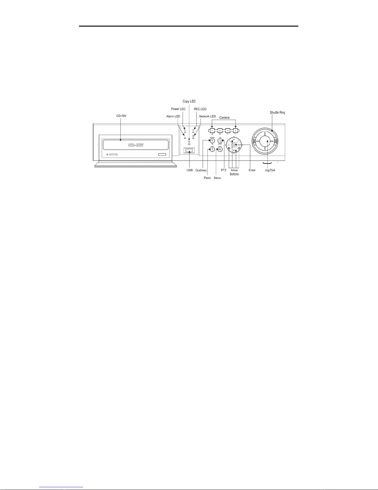
Figure 17 — DVR front panel.
Many of the buttons on the front panel have multiple functions. The following describes each
button and control. Take a few minutes to review the descriptions. You will use these to initially
set up your DVR and for daily operations.
NOTE: A separate Alarm button is not provided. Pressing any keys on the front panel resets
alarm output including the internal buzzer when the alarm is activated. However, when you
are in the menu or PTZ mode, you have to exit the menu or PTZ mode first to reset alarm
output.
Power LED
The POWER LED is lit when the DVR is On.
Alarm LED
The ALARM LED is lit when alarm output or internal buzzer is activated.
REC LED
The REC LED is lit when the DVR is recording. When the DVR is in the panic recording mode,
the RCE LED flickers.
Network LED
The NETWORK LED is lit when the unit is networked either via Ethernet or modem.
11

User’s Manual
Copy LED
The Copy LED is lit when data is being backed up using the internal CD-RW or the USB port.
Camera Buttons (1 to 4)
Pressing the individual camera buttons will cause the selected camera to display full screen. They
are used to enter passwords. The camera buttons also function in the PTZ mode. Pressing
CAMERA 1 zooms in in the PTZ mode, and pressing CAMERA 2 zooms out in the PTZ mode.
CAMERA 3 makes the focus of the PTZ camera near in the PTZ mode. CAMERA 4 makes the focus
of the PTZ camera far in the PTZ mode.
QUAD/SEQ Button
Pressing the
QUAD/SEQ button toggles between quad (2x2) display mode and sequence mode.
Loads a Preset View in the PTZ mode.
PTZ Button
Pressing the PTZ button opens a Pan/Tilt/Zoom screen which allows you to control properly
configured cameras.
In the PTZ mode, pressing the
PTZ button enters the digital zoom mode, and pressing the button
again in the digital zoom mode returns to the live monitoring mode. When the PTZ device is not
installed, pressing the
PTZ button enters the digital zoom mode directly.
Pressing the
PTZ button in the playback mode enters the digital zoom playback mode.
NOTE: When the DVR is in the PTZ mode, a white line will show up around the image.
NOTE: In the digital zoom mode and digital zoom playback mode, a bright small box is laid
over the image. The box indicates the spot to be enlarged.
PANIC Button
Pressing the PANIC button activates panic recording, so the DVR will record video regardless of
the time-lapse or event recording schedule. Press the button again to release the panic recording.
NOTE: When the DVR is recording video, a red dot appears on the screen. When the DVR is
in the panic recording mode, a white
panel flickers.
appears in the red dot, and the REC LED on the front
Menu Button
Pressing the MENU button enters the Main Menu. You will need to enter the administrator
password to access the Main Menu. Pressing the button again closes the current menu or setup
dialog box. Displays the search menu in the playback mode. Loads the PTZ Menu in the PTZ
mode.
12
Four-Channel Digital Video Recorder
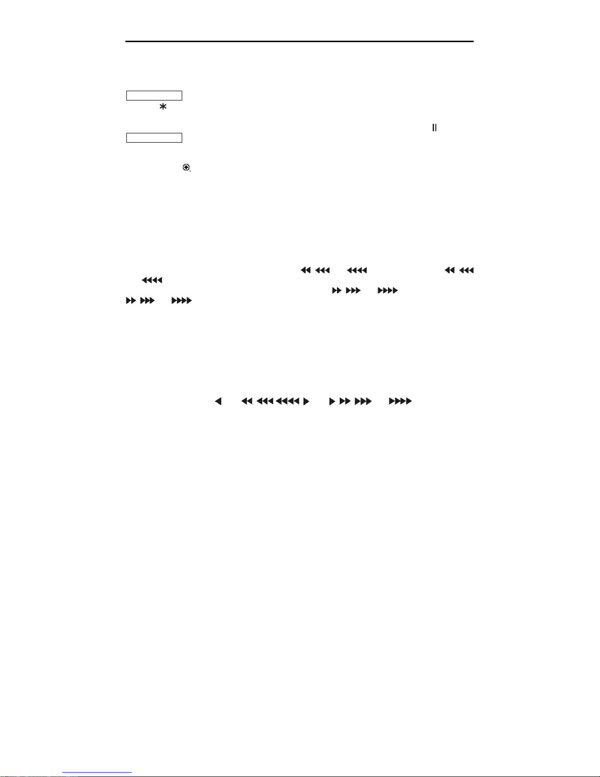
Enter/Pause Button
This button selects a highlighted item or completes an entry that you have made. Pressing the
ENTER/PAUSE button in the live monitoring mode freezes the current live screen, and the screen
displays . Press the button again to return to the live monitoring mode.
Pressing the button in the playback mode will pause the video, and the screen displays . Pressing
ENTER/PAUSE button again in the pause mode goes to the live monitoring mode.
In the digital zoom mode, pressing the button enlarges the specific spot of screen. The enlarged
screen displays .
Arrow Buttons
Arrow buttons are used to navigate through menus and GUI. They are also used to control Pan and
Tilt in the PTZ mode, and to move the specific part of screen that you want to enlarge in the digital
zoom mode.
In the playback mode, Up-Arrow button selects the next image, and Down-Arrow button selects
the previous image. Pressing the Left-Arrow button plays video backward at high speed. Pressing
the button again toggles the playback speed from , and . The screen displays ,
and respectively. Pressing the Right-Arrow button plays video forward at high speed.
Pressing the button again toggles the playback speed from
, and . The screen displays
, and respectively.
Entering Playback mode from Live Monitoring mode can be user password protected.
Shuttle Ring
The Shuttle Ring functions in the Playback mode. The Shuttle Ring is spring loaded and returns to
the center position when released. When you release the ring, it snaps back to the center position
and the video pauses. Turning the ring clockwise plays video forward. Turning the ring
counterclockwise plays video backward. Playback speed varies with the amount the ring is turned.
The playback speeds are
x0.5, , , , x0.5, , , and .
Jog Dial
The Jog Dial functions when playback video has been paused. By turning the jog dial clockwise,
you can play video forward image-by-image. By turning the jog dial counterclockwise, you play
video backward image-by-image.
The Jog Dial also can be used to change numerical values like IP address, date/time and page during
the system setup.
13
User’s Manual
Turning on the Power
Connecting the power cord to the DVR turns on the unit. The unit will take approximately 60
seconds to initialize.
Initial Unit Setup
Before using your DVR for the first time, you will want to establish the initial settings. This
includes items such as time and date, display language, camera, audio, remote control, record mode,
network and password. Your DVR can be set up using various screens and dialog boxes.
Press the
MENU button to enter the setup screens. The Admin Password screen appears.
Figure 18 — Admin Password screen.
Enter the password by pressing the appropriate combination of camera number buttons and then the
button. The factory default password is 4321. There are two Setup screens: Quick Setup and
Normal Setup. The factory default is the Quick Setup screen.
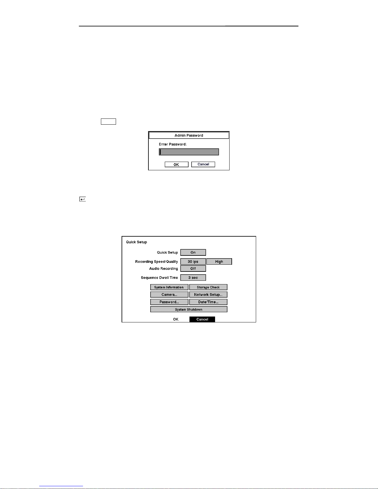
Quick Setup Screen
Figure 19 — Quick Setup screen.
14

Four-Channel Digital Video Recorder
The Quick Setup screen allows you to set up the most commonly used features of your DVR. Use
the arrow buttons to move through the options. Pressing the
button lets you make your
selections.
Highlight the box beside Quick Setup and press the
button to toggle between On and Off. If
you select Off, you will use the Normal Setup screen to change the DVR’s settings.
Highlight the first box beside Recording Speed/Quality, and select recording speeds from as few
as 0.5 ips to as fast as 30 ips (25 ips for PAL).
NOTE: The DVR has a maximum recording speed of 30 ips per camera; however, the
recording speed may not be achieved when averaged over all cameras.
Highlight the second box beside Recording Speed/Quality, and select from Very High, High,
Standard and Low.
Highlight the box beside Audio Recording and select either On or Off.
NOTE: It is the user’s responsibility to determine if local laws and regulations permit
recording audio.
Highlight the box beside Sequence Dwell Time and select from 3 to 60 seconds for the camera
sequence dwell time.
Selecting System Information enters a screen where you can set up system information.
Selecting Storage Check enters a screen where you can check the storage status.
Selecting Camera… enters a screen where you can set up camera information.
Selecting Network Setup… enters a screen where you can set up network information.
Selecting Password… enters a screen where you will be able to change passwords.
Selecting Date/Time… enters a screen where you will be able to set the DVR’s time and date.
Selecting System Shutdown shuts the DVR down. When shutting down the DVR, you need to
confirm that you want to shut down the unit, you will be asked for an administrator password.
NOTE: The Quick Setup mode will be released automatically when the user changes the DVR
settings remotely using the RAS (Remote Administration System) program.
15
 Loading...