

Page 1
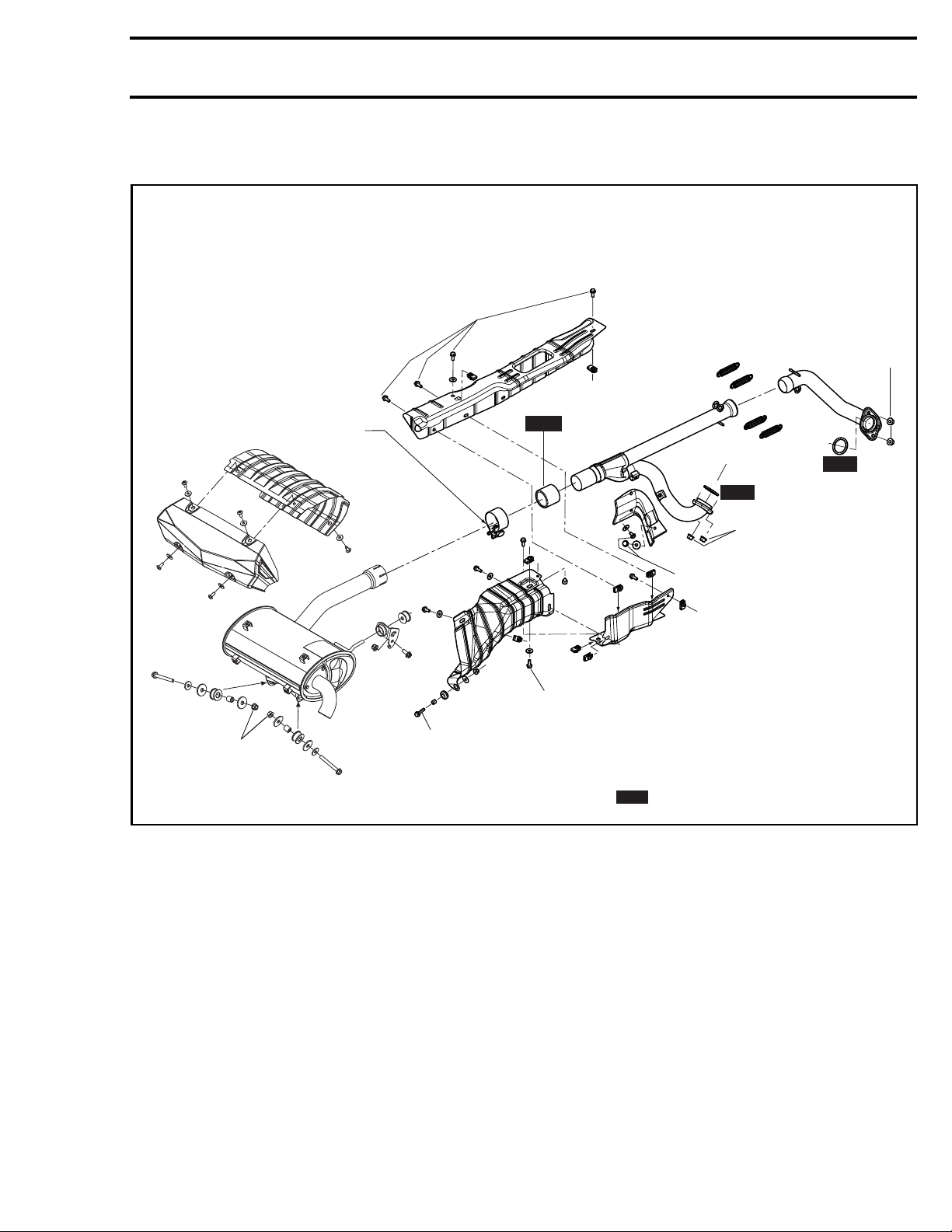
EXHAUST SYSTEM
9 ± 1 N•m
(80 ± 9 lbf•in)
40 ± 1 N•m
(30 ± 1 lbf•ft)
Bolt down,
nut facing outwards
NEW
Subsection 03 (EXHAUST SYSTEM)
13 ± 1 N•m
(115 ± 9 lbf•in)
NEW
NEW
13 ± 1 N•m
(115 ± 9 lbf•in)
9 ± 1 N•m
(80 ± 9 lbf•in)
vmr2016-401-001_a
9 ± 1 N•m
(80 ± 9 lbf•in)
9 ± 1 N•m
(80 ± 9 lbf•in)
10 ± 2 N•m
(89 ± 18 lbf•in)
= Component must be replaced when removed.
NEW
vmr2016-401 1
Page 2
Subsection 03 (EXHAUST SYSTEM)
GENERAL
WARNING
Never touch exhaust system components immediately after the engine has run.
PROCEDURES
SPARK ARRESTER
For spark arre
ster servicing, refer to
MAINTENANCE
PROCEDURES
subsection.
PERIODIC
MUFFLER
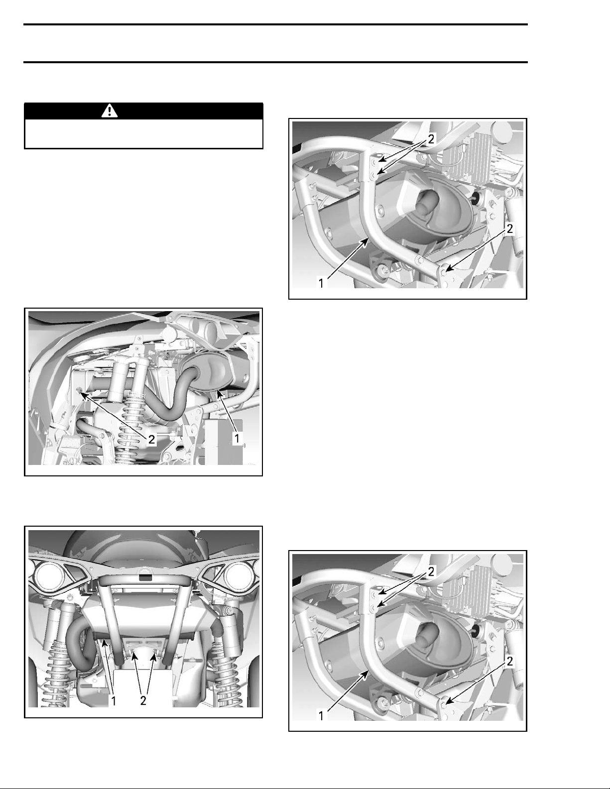
Muffler Removal
1. Loosen exhau
st pipe clamp.
3. Refer to
BODY
and remove both rear bumper
braces.
vmr2012-011-007_d
1. Brace
2. Remove fasteners
4. Remove muffler.
Muffler I
nspection
Check muffler and cover for cracks or other damages. Replace if necessary.
Check if the rubber support is brittle, hard or otherwise damaged. Replace if needed.
smr2012-011-005_a
1. Muffler
2. Loosen cl
amp
2. Remove muffler retaining bolts.
smr2012-011-004_a
REAR VIEW
1. Muffler
2. Remove bolts
Muffler Installation
For the installation, reverse the removal procedure. However, pay attention to the following.
Install n
Refer to
braces.
NOTE: Loosely install all fasteners before tighten-
ing.
vmr2012-011-007_d
1. Brace
2. Secure fasteners
ew exhaust gasket.
BODY
and install both rear bumper
2
vmr2016-401
Page 3
HEAT SHIELD
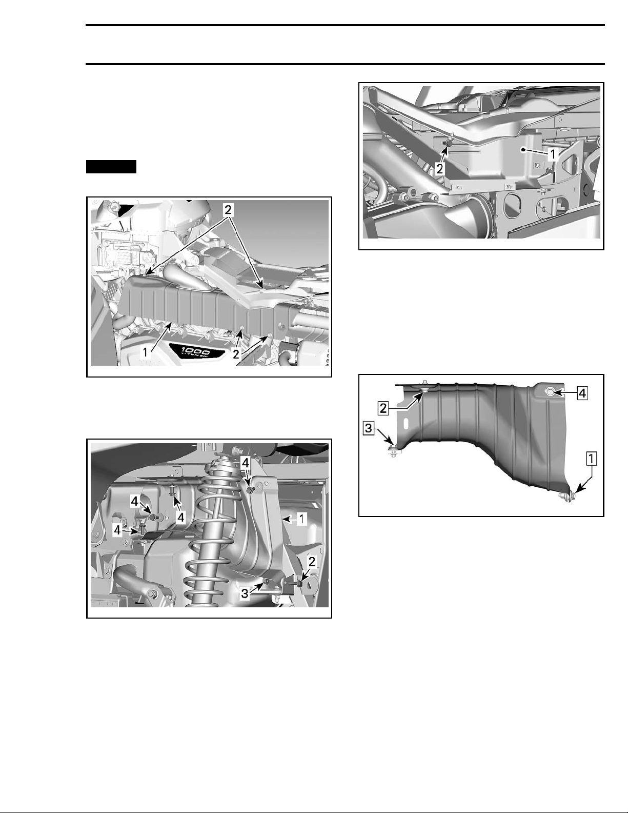
Heat Shield Removal
1. Refer to
2. Remove heat shield retaining bolts.
BODY
and remove LH panel.
Subsection 03 (EXHAUST SYSTEM)
NOTICE
Do not use impact tool to remove or
install heat shield bolts.
vmr2012-011-008_a
1. Heat shield
2. Heat shield bolts
3. Remove muffler for rear and inner heat shield
removal.
vmr2015-014-512_a
1. Inner heat s
2. M6 x 16 b olts
hield
Heat Shield Installation
For the installation, reverse the removal procedure. However, pay attention to the following.
Refer to ex
and follow
ening sequ
ploded view for torque specifications,
ing illustration for rear heat shield tight-
ence.
vmr2015-027-101_a
REAR HEAT SHIELD TIGHTENING SEQUENCE
Y-EXHAUST P I P E
Y-Exhaust Pipe Removal
1. Remove
section.
vmr2015-014-509_a
1. Rear heat shield
2. M6 x 25 bolt
3. M6 elastic nut
4. M6 x 16 bolts with washers
2. Remove
subsection.
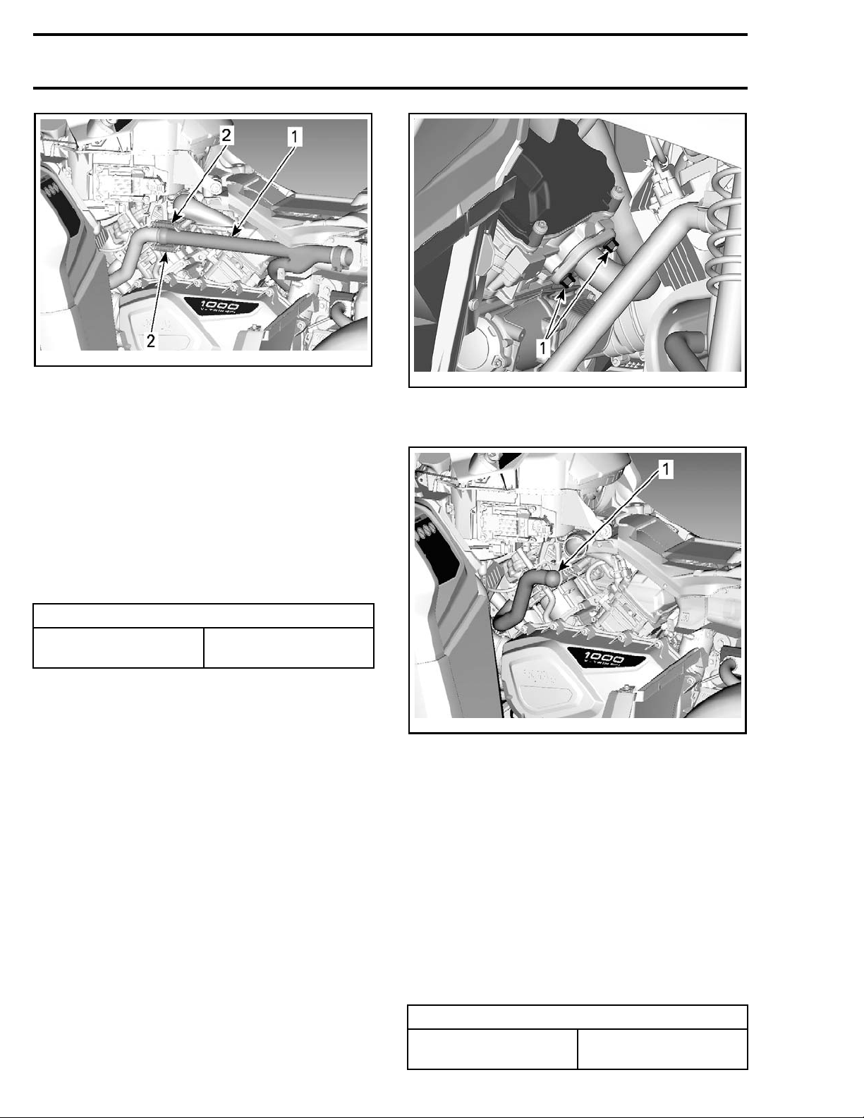
3. Remove the following parts:
– Springs from head pipe
– Y-exhaust pipe retaining nuts on rear cylin-
der.
– Y-exhaust pipe from vehicle.
vmr2016-401 3
MUFFLER
. See procedure in this sub-
HEAT SHIELD
. See procedure in this
Page 4
Subsection 03 (EXHAUST SYSTEM)
vmr2012-011-010_a
1. Y-exhaust pipe
2. Springs
Y-Exhaust Pipe Inspection
Check Y-ex
damages. R
haust pipe for cracks, bending or other
eplace if needed.
vmr2015-027-004_a
1. Head pipe retaining nuts
3. Remove fro
nt head pipe from vehicle.
Y-Exhaust Pipe Installation
The instal
cedure.
Install NEW exhaust gaskets and exhaust pipe retaining nuts.
Properly position exhaust pipe before tightening.
lation is the reverse of the removal pro-
TIGHTENING TORQUE
Head pipe nuts
(rear cylinder)
13 N•m ± 1 N•m
(115 lbf•in ±9lbf•in)
HEAD PIPE (FRONT CYLINDER)
Front Head Pipe Removal
1. Remove
this subsection.
2. From RH side of vehicle, remove head pipe retaining nuts.
Y-EXHAUST PIPE
See procedure in
vmr2012-011-011_a
1. Head pipe
NOTE: The space to remove the front head pipe
is limited. Remove it without force.
Front Head Pipe Inspection
Check head pipe for cracks, bending or other damages. Replace if needed.
Front Head Pipe Installation
The installation is the reverse of the removal procedure. However, pay attention to t he following.
Install NEW exhaust gaskets.
Refer to
QUENCE
EXHAUST SYSTEM TIGHTENING SE-
.
TENING TORQUE
TIGH
Head pipe nuts
4 vmr2016-401
13 N•m ± 1 N•m
lbf•in ±9lbf•in)
(115
Page 5
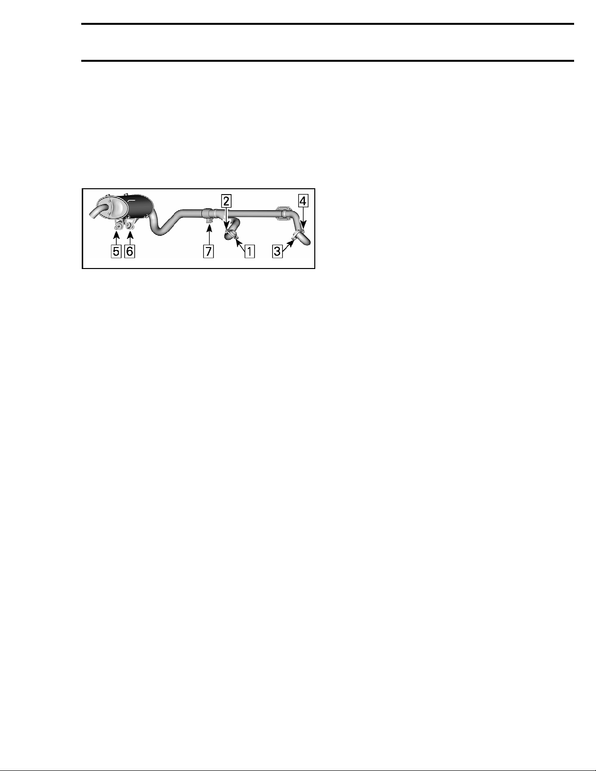
Exhaust System Tightening System
Sequence
Install all nuts and bolts loosely.
Install springs.
Tighten all fasteners as per following tightening
sequence. Refer to exploded view for torque
specifications.
vmr2016-401-002_a
EXHAUST SYSTEM TIGHTENING SEQUENCE
Subsection 03 (EXHAUST SYSTEM)
vmr2016-401 5
 Loading...