

Page 1
Subsection XX (ENGINE REMOVAL AND INSTALLATION)
ENGINE REMOVAL AND INSTALLATION
SERVICE TOOLS
Description Part Number Page
ENGINE LIFTING TOOL ................................................. ............... 529 036 022 ........................................... 5
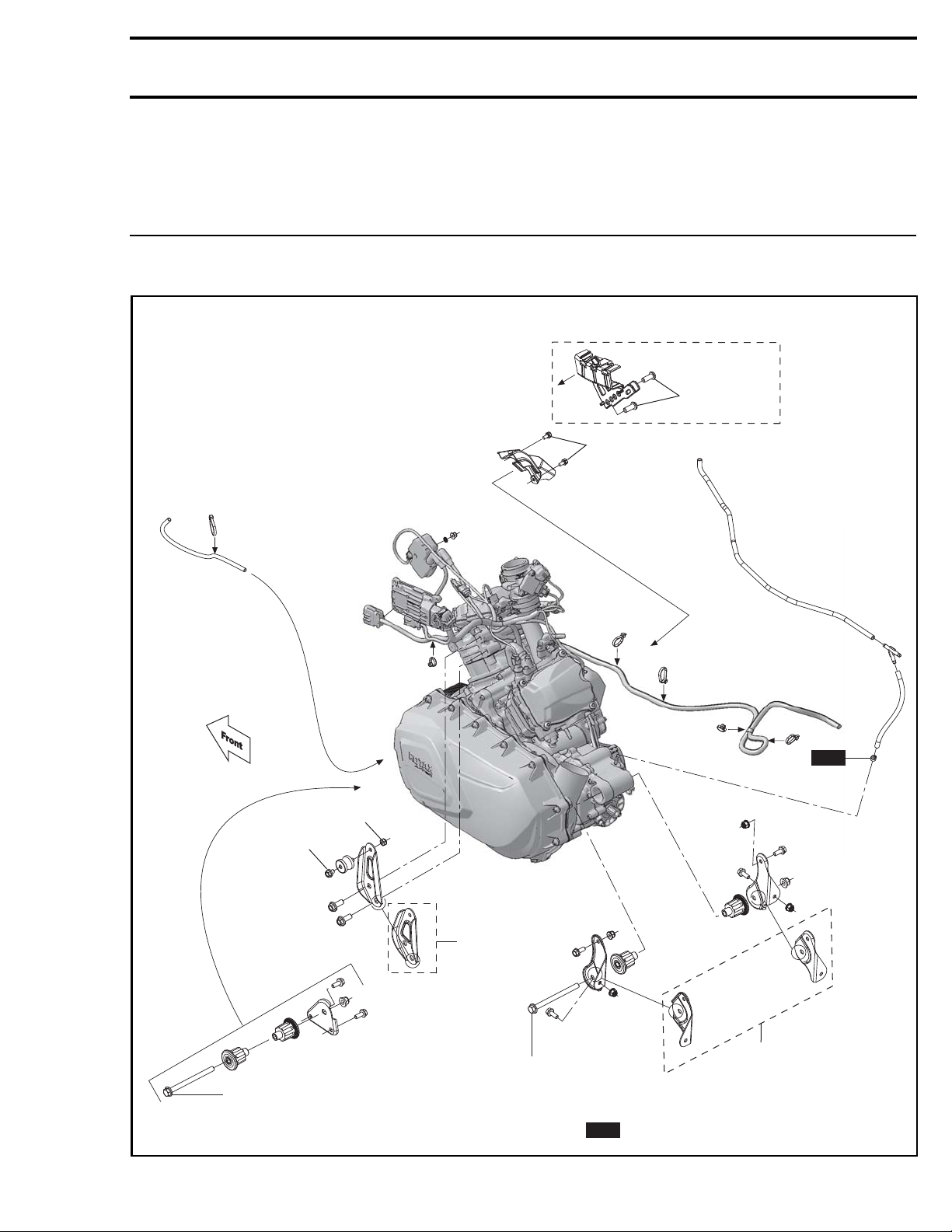
Outlander models
13 ± 2 N•m
(115 ± 18 lbf•in)
7 ± 1 N•m
(62 ± 9 lbf• in )
NEW
4 ± 1 N•m
4.9 ± 0.4 N•m
(43 ± 4 lbf• in )
62.5 ± 7.5 N•m
(46 ± 6 lbf•ft)
vmr2013-009-100_a
vmr2013-009 1
(35 ± 9 lbf• in )
1000
62.5 ± 7.5 N•m
(46 ± 6 lbf•ft)
1000
= Component must be replaced when removed.
NEW
Page 2
Subsection XX (ENGINE REMOVAL AND INSTALLATION)
PROCEDURES
ENGINE REMOVAL
1. Place vehicle on a workstation equipped with
an engine-lifting hoist.
2. Disconnect n
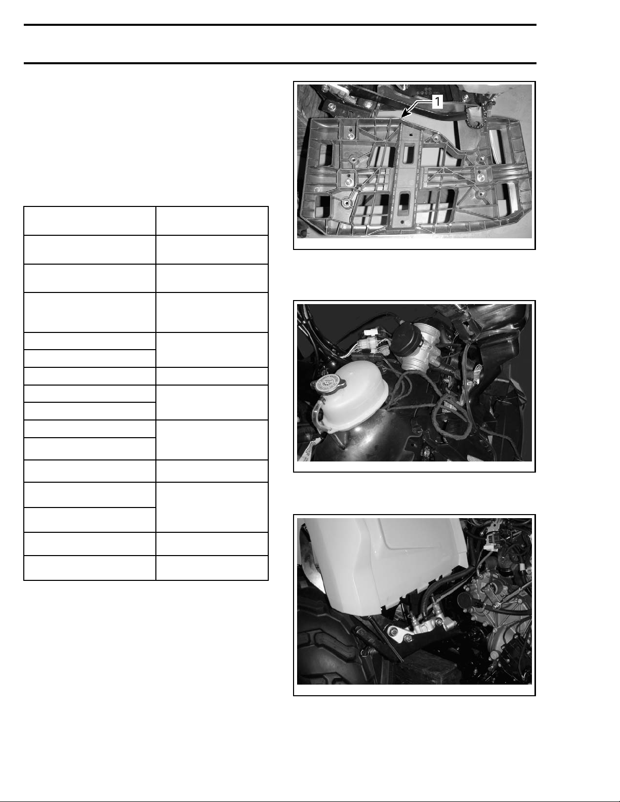
3. Carry out the following operations. Refer to table.
egative (-) cable from battery.
OPERATIONS
Safely lift and support
the vehicle
Release fuel pressure
Drain engine coolant
Remove front body module
Remove RH footrest panel
Remove air filter housing
Remove muffler
Remove exhaust pipes
Remove CVT air inlet
Remove CVT air outlet
Disconnect positive (+)
starter cable
Disconnect TPS connector
Disconnect MAPTS
connector
REFERENCES
(SUBSECTION)
INTRODUCTION
FUEL TANK AND
FUEL PUMP
PERIODIC
MAINTENANCE
PROCEDURES
BODY
AIR INTAKE SYSTEM
EXHAUST SYSTEM
CONTINUOUSLY
VARIABLE
TRANSMISSION (CVT)
STARTING SYSTEM
ELECTRONIC FUEL
INJECTION (EFI)
vmr2012-009-003_a
TYPICAL - OUTLANDER SHOWN
1. RH footrest sup port
5. Move throttle body aside to make room.
2-009-001
vmr201
TYPICAL - THROTTLE BODY ATTACHED ON FRAME
6. Move master cylinder aside to make room.
Remove intake manifold
Remove spark plug cables
INTAKE MANIFOLD
IGNITION SYSTEM
4. Remove RH footrest support.
vmr2012-009-002
TYPICAL - MASTER CYLINDER ATTACHED ON REAR FENDER
7. Move crankcase vent hose as illustrated.
2 vmr2013-009
Page 3
Subsection XX (ENGINE REMOVAL AND INSTALLATION)
vmr2012-009-004_a
TYPICAL
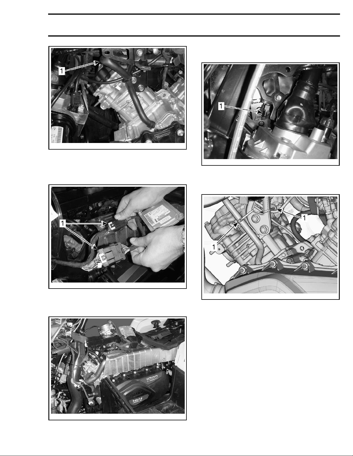
1. Crankcase v
8. Disconnect both engine harness connectors
(HIC).
ent hose
11. Disconnect ignition coil connector.
vmr2012-009-007_a
TYPICAL - FROM LH SIDE
1. Ignition coil connector
12. Remove the following locking ties.
2-009-005_a
vmr201
TYPICAL
1. Engine harness connectors (HIC)
9. Move EC
M as illustrated.
vmr2012-009-008_a
TYPICAL
1. Locking ties
13. Remove plastic cover from engine.
vmr2012-009-006
TYPICAL
10. Cut locking ties from ignition coil harness.
vmr2013-009 3
Page 4
Subsection XX (ENGINE REMOVAL AND INSTALLATION)
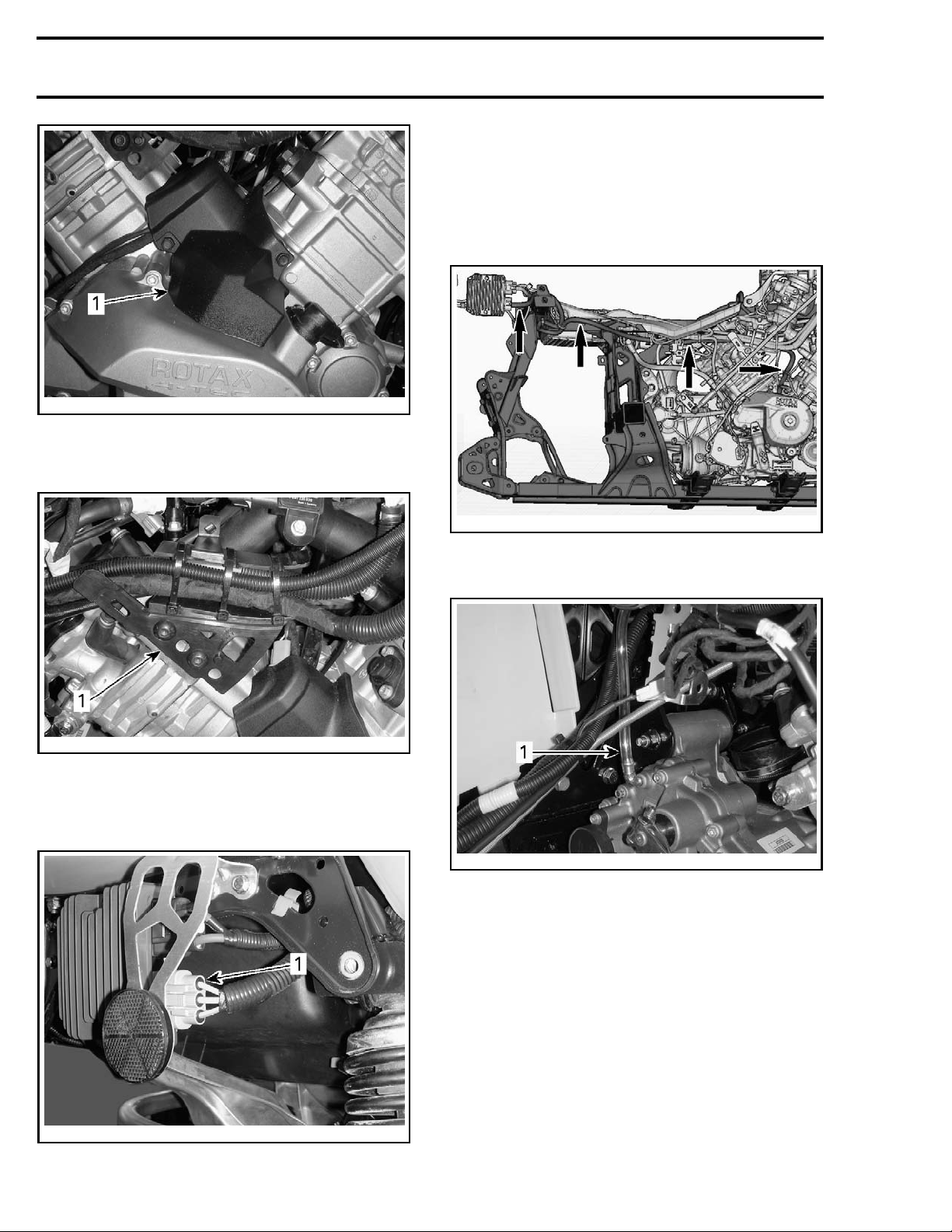
16. Remove magneto harness from its location
along vehicle and gather it in a bundle near
engine.
NOTE: It may be necessary to slightly lift the rear
body module to ease magneto harness removal.
Refer to
vmr2012-009-009_a
TYPICAL
1. Plastic cover
14. Remove harnesses s upport from engine.
vmr2012-0
MAGNETO HARNESS (SOME PARTS REMOVED FOR CLARITY)
BODY
09-011_a
subsection.
vmr2012-009-010_a
TYPICAL
1. Harnesses s uppo rt
15. Disconnect magneto connector from voltage
regulator rectifier.
17. Disconnect vent hose from gearbox.
vmr2012-009-012_a
TYPICAL - OUTLANDER SHOWN
1. Vent hose
18. Disconnect coolant hoses as illustrated.
vmr2012-043-013_b
TYPICAL - OUTLANDER SHOWN
neto connector
1. Mag
4 vmr2013-009
Page 5
Subsection XX (ENGINE REMOVAL AND INSTALLATION)
vmr2012-009-025_a
500/650/800R ENGINES - SOME PARTS REMOVED FOR CLARITY
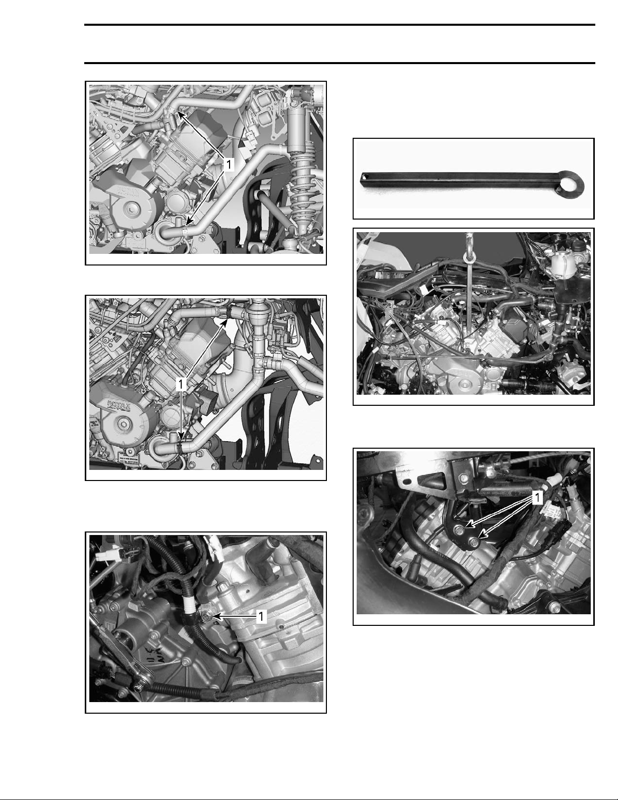
1. Disconnect the following coolant hoses
Engine Lifting
1. Install the ENGINE LIFTING TOOL (P/N 529 036
022)
on engine.
529036022
2-009-013_a
vmr201
1000 ENGINE - SOME PARTS REMOVED FOR CLARITY
1. Disconnect the following coolant hoses
19. Remove
main ground wire from engine.
vmr2012-009-015
TYPICAL
2. Remove upper retaining screws from engine.
vmr2012-009-016_a
LH SIDE
1. Upper retaining screws
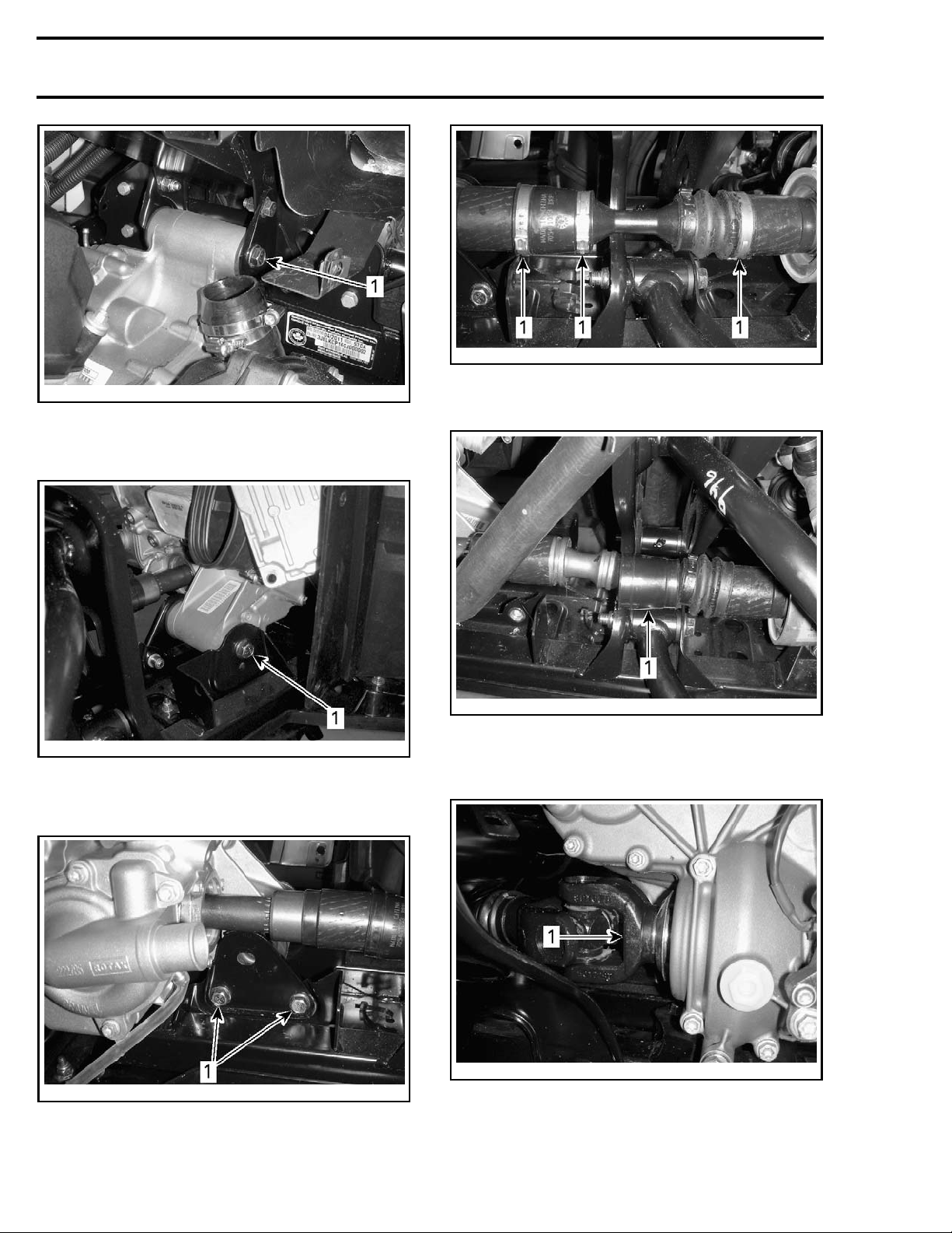
3. Remove rear retaining bolt from engine.
vmr2012-009-014_a
TYPICAL - OUTLANDER SHOWN
n ground wire
1. Mai
vmr2013-009 5
Page 6
Subsection XX (ENGINE REMOVAL AND INSTALLATION)
vmr2012-009-020_a
1. Oetiker clamps
vmr2012-009-017_a
LH SIDE
1. Rear retaining bolt
4. Remove front retaining bolt from engine.
7. Move front propeller shaft bellows forward.
vmr2012-009-018_a
LH SIDE
1. Front retaining bolt
5. Remove engine support plate from frame.
vmr2012-009-019_a
RH SIDE
1. Engine support plate screws
6. Remove the following Oetiker clamps from
front propeller shaft.
vmr2012-009-021_a
1. Front propeller shaft bellows
8. Remove propeller shaft screw from gearbox
output shaft.
vmr2012-009-022_a
1. Rear propeller shaft screw
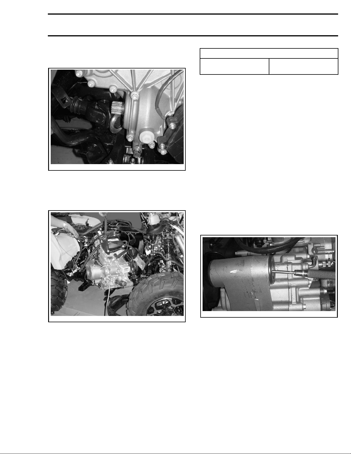
9. Slightly lift engine and move it forward to disconnect rear propeller shaft from engine.
6 vmr2013-009
Page 7
Subsection XX (ENGINE REMOVAL AND INSTALLATION)
10. Move propeller shaft yoke downwards to
make room.
vmr2012-009-023
TYPICAL
11. Move engin
peller sha
e rearward to disconnect front pro-
ft from engine.
12. Remove engine by the RH side.
TORQUE
Engine retaining bolts
62.5 N•m ± 7.5 N•m
(46 lbf•ft ± 6 l
bf•ft)
6. If applicable, fill engine as per specification. Refer to
LUBRICATION SYSTEM
7. Fill and blee
ODIC MAINTE
d cooling system. Refer to
NANCE PROCEDURE
subsection.
PERI-
subsec-
tion.
8. Check for any leaks.
9. Reinstall all the remaining parts as the reverse
of removal procedure. Refer to exploded views
and proper subsections.
10. Test drive
ENGINE MOU
REPLACEM
vehicle to confirm proper operation.
NTS
ENT
NOTE: Use the same procedure for the front and
rear engine mounts.
Engine Mo
unt Removal
Insert a punch into engine mount bushing and
push the opposite engine mount out.
12-009-024
vmr20
TYPICAL
tmr2011-007-011
AL
TYPIC
Engine Mount Installation
ENGINE INSTALLATION
The installation is the reverse of the removal pro-
The ins
cedur
cedure. However, pay attention to the following.
1. Inspect condition of engine mounts.
2. Install engine on vehicle.
3. Install all engine retaining bolts loosely.
4. Install and tighten propeller shaft screw. Refer
to
REAR DRIVE
subsection.
5. Tighten engine retaining bolts to specification.
vmr2013-009 7
tallation is the reverse of the removal pro-
e.
 Loading...