

Page 1
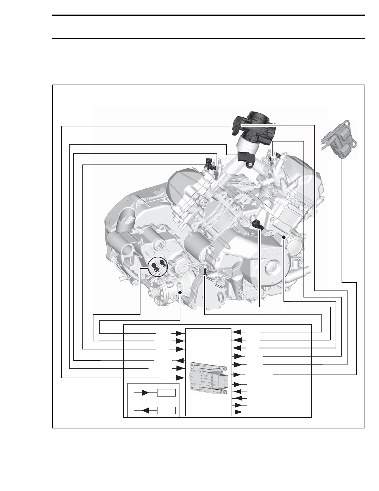
Subsection 01 (ENGINE MANAGEMENT SYSTEM (EMS))
ENGINE MANAGEMENT SYSTEM (EMS)
Engine with Gearbox using External Switches
VSS
GBPS
CTS
ECM
INJ 2
MAPTS
TPS
IN
ECM
OUT
ECM
vmr2015-064-001_aen
vmr2016-127 1
4WD
OPS
CPS
INJ 1
IACV
IGN COIL
COOLING FAN
IGN SW
START SW
STARTER SOLENOID
FUEL PUMP
Page 2
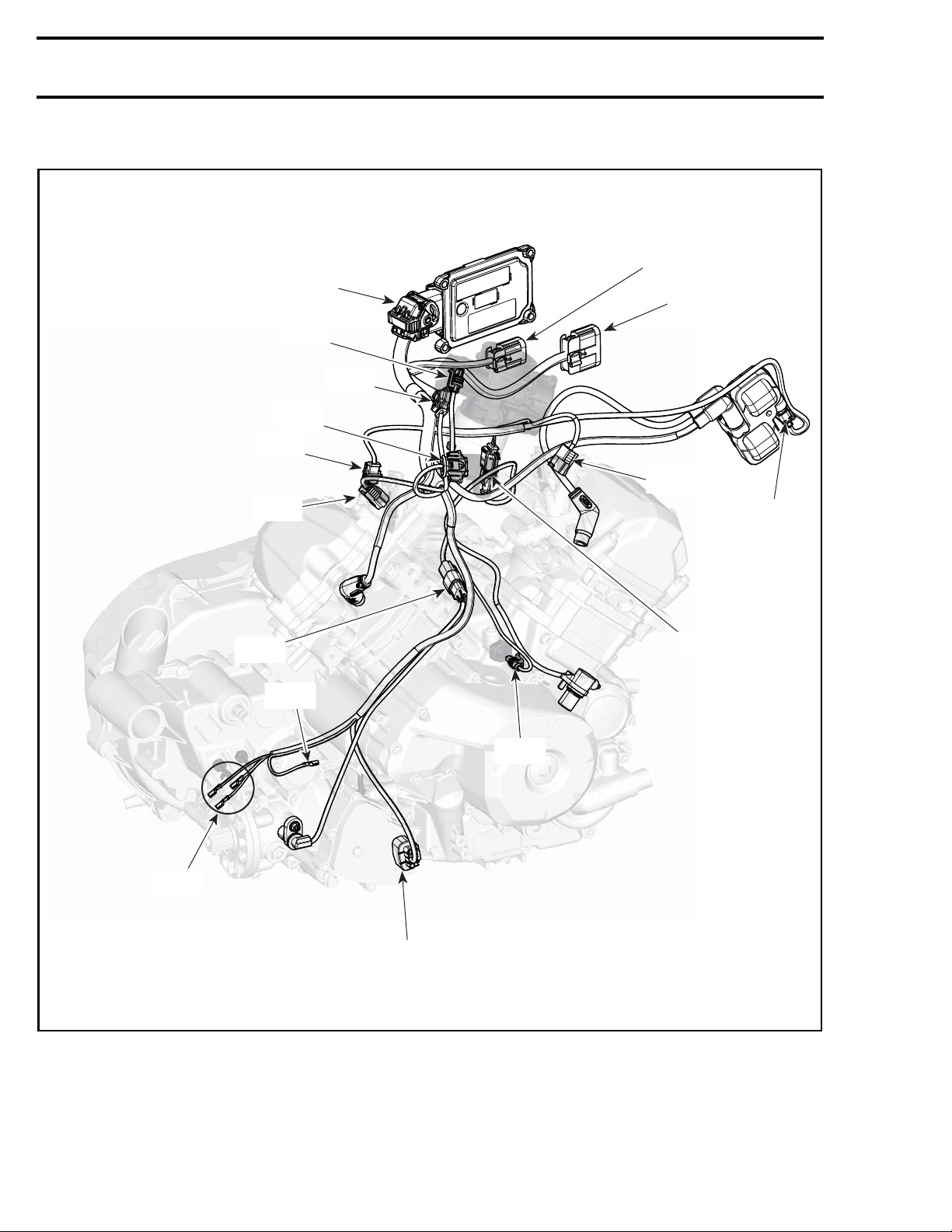
Subsection 01 (ENGINE MANAGEMENT SYSTEM (EMS))
Engine with Gearbox using External Switches
ECM
IACV
TPS
MAPTS
CTS
HIC2
HIC1
INJ1
GBPS
VSS
INJ2
SD
BA
CPS
OPS
MD
vmr2015-064-002_a
2 vmr2016-127
Page 3
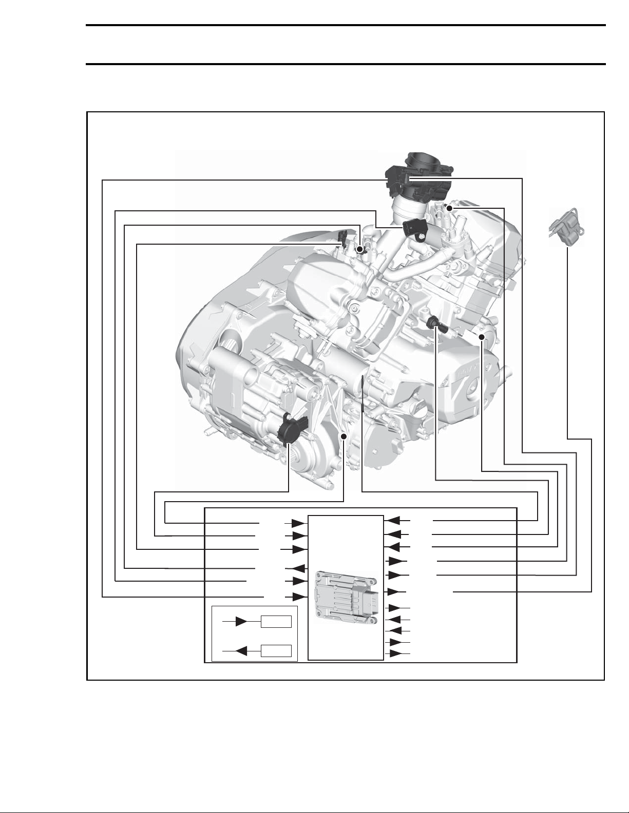
Engine with Gearbox using GBPS
Subsection 01 (ENGINE MANAGEMENT SYSTEM (EMS))
VSS
GBPS
CTS
ECM
INJ 2
MAPTS
TPS
IN
ECM
4WD
OPS
CPS
INJ 1
IACV
IGN COIL
COOLING FAN
IGN SW
START SW
OUT
ECM
vmr2015-125-001_a
vmr2016-127 3
STARTER SOLENOID
FUEL PUMP
Page 4
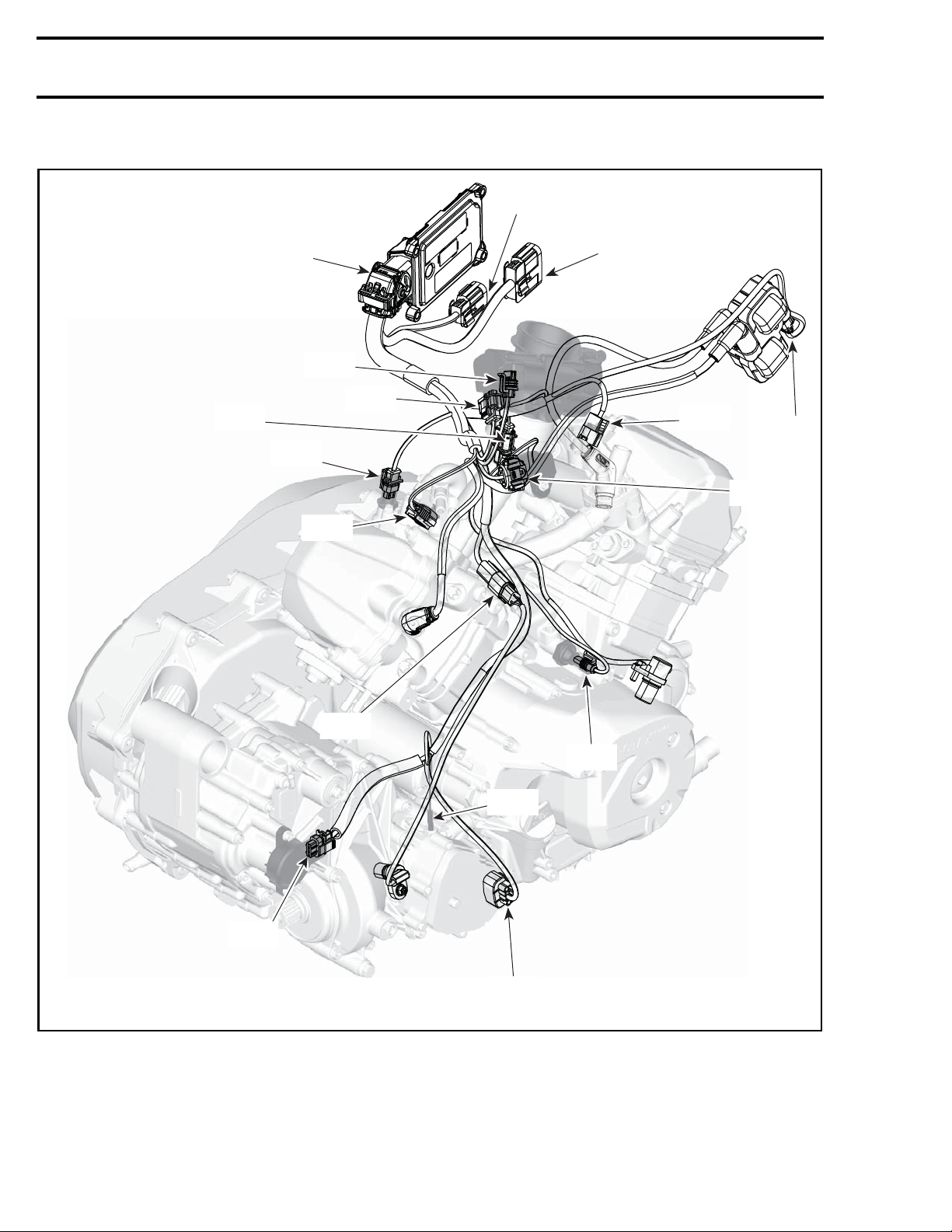
Subsection 01 (ENGINE MANAGEMENT SYSTEM (EMS))
Engine with Gearbox using GBPS
HIC2
CPS
ECM
CTS
IACV
INJ2
TPS
HIC1
INJ1
BA
MAPTS
vmr2015-125-002_a
VSS
OPS
SD
GBPS
MD
4 vmr2016-127
Page 5
Subsection 01 (ENGINE MANAGEMENT SYSTEM (EMS))
ABBREVIATION DEFINITION
BA Ignition coil
CPS Crankshaft position sensor
CTS Coolant tempe
ECM
GBPS Gear box position sensor
HIC1‡
HIC2‡
IACV
INJ1 Injector 1 (fr
INJ2 Injector 2 (rear)
MAPTS
MD 4WD Actuator
OPS Oil pressure
SD 4WD Signal
TPS
VSS
‡Refer to applicable
CONNECTORS
Electronic control module
Harness intercon nect 1
Harness intercon nect 2
Idle air control valve
Manifold absolute pressure and
temperature sensor
Throttle position sensor
Vehicle speed sensor
WIRING HARNESS AND
ubsection for the vehicle harness.
s
rature sensor
vmr2008-132-005
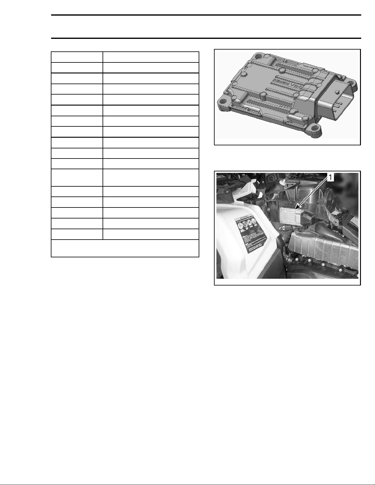
TYPICAL - ECM
ont)
The ECM is located behind the LH panel.
switch
GENERAL
SYSTEM DESCRIPTION
The HIC# con
to the power
There are 6 main systems that are controlled by
the engine management system (EMS):
1. Electroni
2. Cooling system (cooling fan)
3. Ignition system
4. Starting s
5. Fuel pump system
6. D.E.S.S. system.
NOTE: For further information related to these
systems, refer to the applicable subsection.
The ECM (E
point of t
nectors connect the vehicle harness
train harness.
c Fuel Injection (EFI)
ystem
ngine Control Module) is the central
he engine management system.
vmr2012-022-002_a
LH PANEL REMOVED
1. ECM loca
tion
The ECM reads input signals from various
switches, controls, and sensors, that it compares
to pre-determined parameters, makes computations, and provides control signal outputs required
for proper engine management.
The ECM
the gau
tion ex
CON
to
LIGHT
tions
also interacts through CAN bus with
ge module for various functions, informa-
change and display of messages. Refer
TROLLER AREA NETWORK (CAN)
S, GAUGE AND ACCESSORIES
subsec-
.
and
The ECM also features a permanent memory that
will store the information on the various ignition
keys programmed to the vehicle, fault codes, customer information, and other engine information,
even when the battery is removed from the vehicle.
vmr2016-127 5
Page 6

Subsection 01 (ENGINE MANAGEMENT SYSTEM (EMS))
Engine RPM Limiter
The ECM limits the maximum engine speed with
the shifter selected to any position. It uses the
CPS and the GBPS for this function.
An override switch, on the handlebar, allows the
engine to be run at a higher speed than the RPM
limiter when more power is needed in reverse operation. Refer to
SORIES
.
LIGHTS, GAUGE AND ACCES-
Vehicle Speed Limiter
The ECM will limit the maximum vehicle speed.
For this purpose, the ECM uses the VSS and the
GBPS.
Drowned Mode (Flooded Engine)
If the engine is fuel-flooded and does not start,
this special mode can be activated to prevent fuel
injection and ignition while cranking. Proceed as
follows to activate it.
With the ignition key set to ON and the engine
stopped, press and HOLD the throttle lever to
WOT position (wide open throttle).
Press the start button. Drowned mode is now on.
Releasing the throttle lever will bring back the nor-
mal mode.
that they can be monitored. Some problems will
turn on a warning lamp or will set the engine in
limp home mode. Refer to
FAULT CODES
section for more information.
DIAGNOSTIC AND
Monitoring System
The ECM monitors the electronic components
of the fuel injection system and also parts of the
electrical system.
For more information, refer to
FAULT CODES
.
DIAGNOSTIC AND
Limp Home Mode
The ECM may automatically set default parameters to the engine management to ensure the adequate operation of the engine if a component of
the fuel injection system is not operating properly. The engine will operate with reduced performance to protect the engine. In more severe
cases, the engine RPM will be limited, also to protect the engine.
These performance-reduced modes allow the
rider to go back home which would not be otherwise possible. Refer to the
FAULT CODES
subsection.
DIAGNOSTIC AND
Diagnostic Mode
The ECM features a self-diagnostic mode when
the ignition key is turned on. However, some
components need the engine to be running so
6 vmr2016-127
 Loading...