

Page 1

Subsection 01 (ELECTRONIC FUEL INJECTION (EFI))
ELECTRONIC FUEL INJECTION (EFI)
SERVICE TOOLS
Description Part Number Page
ECM ADAPTER TOOL................................................................... 529 036 166 ............................................. 5
FLUKE 115 MULTIMETER ............................................................ 529 035 868 ............................................. 5
OETIKER PLIERS........................................................................... 295 000 070 ........................................... 10
SERVICE PRODUCTS
Description Part Number Page
LOCTITE 243 (BLUE)..................................................................... 293 800 060 ...............................10, 16, 21
XPS SYNTHETIC GREASE.... ....................................... .................. 293 550 010 ........................................... 18
GENERAL
WARNING
Fuel is flammable and explosive under certain conditions. Ensure work area is well ventilated. Do not smoke or allow open flames or
sparks in the vicinity.
WARNING
Fuel lines remain under pressure at all times.
Always proceed with care and use appropriate safety equipment when working on pressurized fuel system. Wear safety glasses.
Wipe off any fuel spillage. Do not allow fuel
to spill on hot engine parts and/or on electrical connectors.
WARNING
Replace any damaged, leaking or deteriorated fuel lines or connections. Always,
pressurize the fuel system if any fuel related
component was disconnected or removed.
Proceed with care when removing/installing
high pressure test equipment.
SYSTEM DESCRIPTION
Refer to the appropriate
SYSTEM
various EFI system components.
The electronic fuel injection system (EFI) is com-
prised of various sensors used for detecting ongoing operating conditions of the engine and vehicle,
and includes all the components that perform the
required adjustments to the engine.
subsection for a general layout of the
ENGINE MANAGEMENT
Electrical System
ECM (Electronic Control Module)
The ECM controls the electrical system and the
engine management functions, by p rocessing the
information given by various sensors.
EFI Sensors
The ECM reads the inputs from the sensors
which it compares to predetermined parameters
stored in the ECM, makes computations, and activates the outputs accordingly (injectors, ignition
coils etc.).
Signals from sensors are used by the ECM to determine the injection and ignition parameters (referenced to fuel maps) as required to maintain the
optimum air-fuel ratio.
Air Intake System
Refer to the applicable
section for additional information.
Throttle Body
The throttle body is mounted on the intake manifold.
Air for combustion, drawn in by the engine, flows
through the air intake system, then through the
throttle body where it is regulated by a throttle
plate.
AIR INTAKE SYSTEM
sub-
vmr2016-423 1
Page 2
Subsection 01 (ELECTRONIC FUEL INJECTION (EFI))
The fuel pressure applied to the fuel rails is regulated by the fuel pressure regulator located in the
fuel pump module.
Fuel Injectors
The fuel injectors are used to inject fuel into the
intake ports of the cylinder head. One injector is
used per cylinder.
Fuel Pump
An electric fuel pump with an integrated pressure
regulator and fuel system filters is used. For more
details on the fuel pump unit, refer to
AND FUEL PUMP
vmr2015-073-001_a
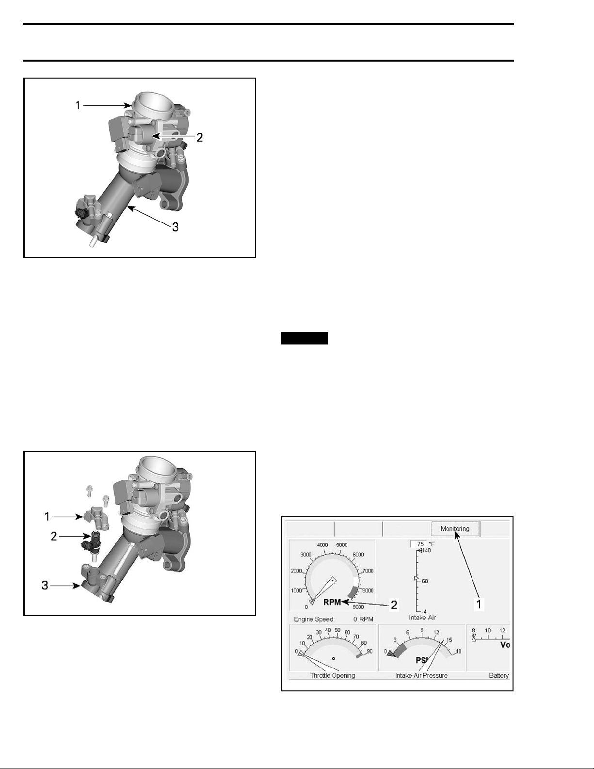
1. Throttle body
2. Idle air control valve (IACV)
3. Intake manifold
Fitted on the throttle body, a throttle plate regulates the amount of air that enters the engine.
A TPS is incorporated on the throttle body. It provides a signal t o the ECM of the actual throttle
plate position.
An idle air control valve (IACV) is also incorporated
on the throttle body, It allows the ECM to control
the idle speed while the throttle plate is closed.
Fuel System
Refer to the applicable
PUMP
subsection for additional information.
FUEL TANK AND FUEL
ADJUSTMENT
IDLE SPEED
Idle speed is not adjustable. The ECM controls
the IACV.
NOTICE
idle stop screw. It is calibrated at the factory.
If the screw adjustment is changed, the throttle body must be replaced.
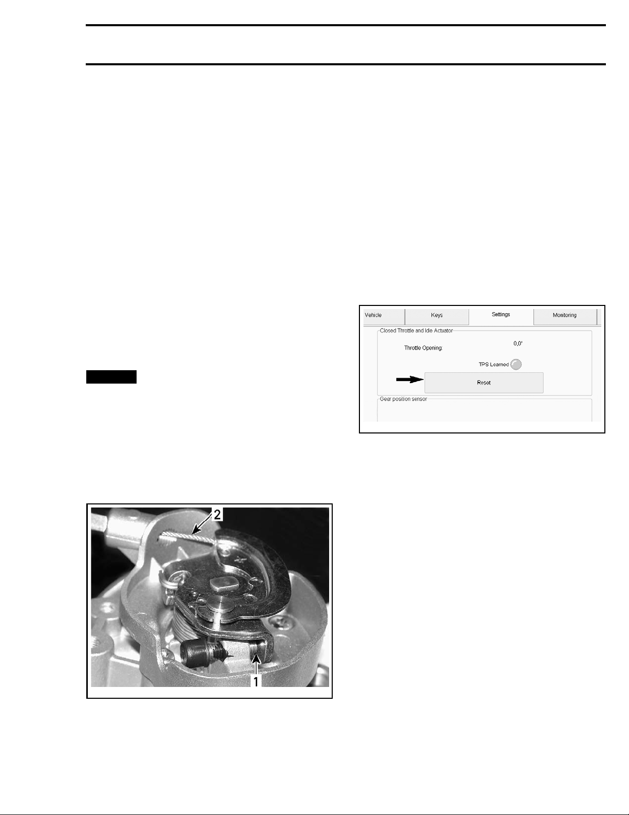
The vehicle multifunction gauge can provide an accurate digital readout of the engine's idle speed.
The engine RPM may also be verified using the applicable B.U.D.S. software version, refer to
MUNICATION TOOLS AND B.U.D.S.
In B.U.D.S., click the following:
– Read Data button
– Monitoring tab
– ECM tab.
FUEL TANK
subsection.
Never attempt to adjust the sealed
COM-
subsection.
5-073-002_a
vmr201
1. Fuel rail
2. Fuel Injector
e manifold
3. Intak
Fuel Rail
Two fuel rails, one for each injector, are mounted
on the intake manifold. The fuel rails, which are
used to secure the injectors to the manifold, also
provide to the injectors the fuel pressure that they
receive from the fuel pump.
2
2-026-150_a
vmr201
VERIFYING ENGINE RPM USING B.U.D.S.
1. Monitoring tab
2. Engine
RPM indication
vmr2016-423
Page 3
Subsection 01 (ELECTRONIC FUEL INJECTION (EFI))
NOTE: The multifunction gauge and B.U.D.S. use
the same signal to provide the engine RPM indication.
CLOSED THROTTLE AND IDLE
ACTUATOR RESET
This operation performs a reset of the values in
the ECM.
This reset is very important. The setting of the
TPS will determine the basic parameters for all
fuel mapping and several ECM calculations and
the setting of the idle air control valve will determine the basic parameters for the idle speed control of the engine.
Closed throttle and idle actuator reset must be
done if:
– TPS is loosened, removed or replaced
– Throttle body is replaced
– Idle air control valve is replaced
– ECM is replaced.
NOTICE
lead to poor engine performance and emission
compliance could possibly be affected. In addition, improper IACV reset may lead to poor
engine starting, improper idle ( too low or too
high) and engine stop on deceleration.
Remove throttle body cap and ensure the throttle
cam of throttle body rests against set screw without any tension in the cable.
An improperly set TPS or IACV may
Open throttle approximately one quarter then
quickly release. Repeat 2 - 3 times to settle throttle plate. If stopper does not rest against its stop
lever, perform throttle cable adjustment. Refer to
THROTTLE CABLE
in this subsection.
To reset IACV and TPS, perform the following:
1. Connect the vehicle to the latest applicable
B.U.D.S. version, refer to
TOOLS AND B.U.D.S.
COMMUNICATION
subsection.
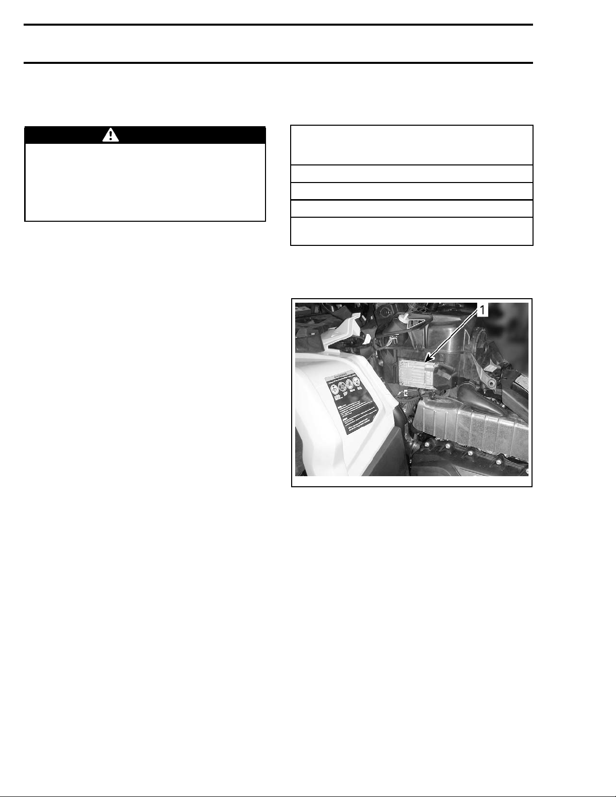
2. In B.U.D.S., click the following:
– Read Data button
– Setting tab
– ECM tab
3. Click on the Reset button in the Closed Throt-
tle and Idle Actuator area.
045-010_a
vmr2016-
If operation is wrong, an error message will be displayed.
If TPS is
setting
ECM will
the sett
not within the allowed range while re-
the Closed Throttle and Idle Actuator, the
generate a fault code and will not accept
ing. Repeat the reset procedure.
4. Start engine and make sure it operates normally through its full engine RPM range. If
fault codes appear, refer to
FAULT CODES
subsection for more informa-
DIAGNOSTIC AND
tion.
TROUBLESHOOTING
DIAGNOSTIC TIPS
Engine problems are not necessarily related to the
fuel injection system.
mportant to ensure that the engine and
vmr2006-014-064_b
act here
1. Cont
2. Free-play here
vmr2016-423 3
It is i
lsion system, fuel delivery and electrical
propu
ms are functioning normally.
syste
For diagnostics purposes, use B.U.D.S. software.
See
COMMUNICATION TOOLS AND B.U.D.S.
subsection.
Page 4
Subsection 01 (ELECTRONIC FUEL INJECTION (EFI))
After a problem has been solved, be sure to clear
the fault(s) in the ECM using the B.U.D.S. software.
WARNING
Electrical actuators and electronic modules
may be powered up as soon as the ignition
switch is set to ON and emergency engine
stop switch is set to RUN. Always disconnect
the battery prior to disconnecting any electrical or electronic parts.
Never use a b
tute the bat
tion errati
attery charger to temporarily substi-
tery as it may cause the ECM to func-
cally, or not at all.
Check related-circuit fuse solidity and condition
with an ohmmeter. A visual inspection could lead
to a false diagnosis.
Electrica
l Related Problems
It is important to check the following in the electrical system:
– Battery vo
ltage
– Fuses
– Ground connections
–Wiringan
d connectors.
Ensure that all electronic components are genuine
OEM. Any modification to the wiring harness may
lead to poor system operation or generate fault
codes.
Electrical Connections
Pay parti
and pins a
or out of
cular attention to ensure that terminals
re not out of their connectors, corroded,
shape.
When probing terminals, pay a ttention not to deform the terminals as this could cause a loose or
intermittent connection that would be difficult to
troubleshoot.
PROCEDURES
ENGINE CONTROL MODULE
(ECM)
NOTE: This wakes up the ECM, which then turns
on the following. If the following do not turn on,
check ECM fuse (PF1 (F5 and F8)).
QUICK INDICATION THAT ECM IS FUNCTIONING
(assuming the
in good work in g order)
Multifuncti
Fuel pump turns on for approx. 5 seconds.
Rear lights turn on.
Headlamps t
position).
on gauge turns ON.
urnon(ignitionkeyonwithlights
observed component is
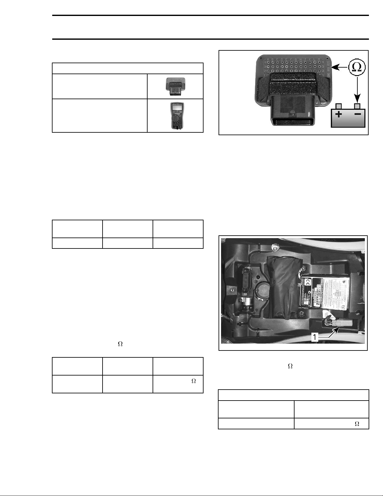
ECM Access
Refer to
vmr2012-022-002_a
LH PANEL REMOVED
1. ECM location
BODY
and remove the LH panel.
ECM Connector
There is one connector connected to the ECM. It
links:
– Engine harness
– Vehicle system control harness.
For connector information, cleaning and probing,
refer to
subsection.
WIRING HARNESS AND CONNECTORS
As a first troubleshooting step, always check for
applicable fault codes using B.U.D.S. software.
Quick Test to Validate ECM Operation
Turn ignition key to ON.
Set eme
4 vmr2016-423
rgency engine stop switch to RUN.
Page 5
Subsection 01 (ELECTRONIC FUEL INJECTION (EFI))
Testing the ECM Power Supply
REQUIRED TOOL
ECM ADAPTER TOOL
(P/N 529 036 166)
FLUKE 115 MULTIMETER
(P/N 529 035 868)
1. Disconnect ECM connector.
2. Install the
nector.
3. Install a jumper wire between K1 and M4 on the
ECM adapter tool.
4. Turn the ignition switch to ON.
5. Set emerge
6. Set multimeter to Vdc and check for voltage as
follows.
ECM
ADAPTER
ECM adapter tool on the ECM con-
ncy engine stop switch to RUN.
BATTERY VOLTAGE
smr2009-030-010_a
If any measurement is out of specification, refer to
POWER DISTRIBUTION
and check all grounds.
Tes ti ng the C A N Res i s t o r
Remove the DPS1 connector (4-pin connector)
from DPS module (if so equipped). Refer to
STEERING SYSTEM
1. Remove seat to access the diagnostic link connector (DB).
2. Remove diagnostic link connector from its
holder.
subsection.
L1 Negative post Battery voltage
If voltage is not measured, check the following:
–ECMfuse
– Main relay
– Wiring and connections, refer to the
DIAGRAM
.
WIRING
Testing the Continuity of ECM Ground
Circuits
1. Disconnect ECM connector.
2. Install the ECM adapter tool on ECM connector.
3. Set multimeter to
nals as per following table.
ECM
ADAPT
Pins M3 and
ER
M4
and probe adapter termi-
BATTERY
POST
Ground
RESISTANCE
Closeto0
tinuity)
(con
2-023-003_a
smr201
1. Diagnostic link connector (DB)
3. Set a multimeter to setting.
4. Measure the resistance o f the CAN resistors as
per following table.
CAN RESISTOR TEST
DIAGNOSTIC LINK
CONNECTOR
Pins 1 and 2 Approximately 60
RESIS
TANCE
vmr2016-423 5
Page 6
Subsection 01 (ELECTRONIC FUEL INJECTION (EFI))
TEST RESULT
READING RESULT
Approximately
60
Approximately
120
Infinite
(open circuit)
ECM and CLUSTER CAN wires
and resistors good
ECM CAN resistor open, or
CLUSTER CAN resistor
open, or
CANwiretoCLUSTER
or ECM open
CAN wire to DB connector
open circ uit
If 120 ohms is read, isolate the CLUSTER from
CAN by disconnecting it and measuring again at
the diagnostic link connector.
If 120 ohms is still read, the ECM CAN resistor and
wires are good. Check for continuity of the CLUSTER CAN wires, refer to
WIRING DIAGRAM
.
If an open circuit is read, the ECM CAN resistor
(or w ire) is open. Check for continuity of the ECM
CAN wires, refer to
WIRING DIAGRAM
to deter-
mine if the wires or the resistor is at fault.
If the CAN resistor of a module is at fault, replace
that module.
If a module cannot communicate and the CAN re-
sistor and wires test good, try a new module.
5. Reconnect DPS1 to DPS module,
3. If a new ECM is installed, refer to
THE ECM
in this subsection.
REPLACING
Replacing the ECM
1. Transfer ECM data. Refer to
TRANSFER
2. Perform the
ACTUATOR RESET
for complete procedure.
CLOSED THROTTLE AND IDLE
.
3. Program the vehicle ignition key(s) in the new
ECM.
4. Calibrate the IACV. Refer to
in this subsection.
TION
ECM DATA
IACV CALIBRA-
ECM Data Transfer
To transfer the original ECM recorded information
to the new ECM, use the B.U.D.S. software and
proceed as follows.
1. Connect the original ECM to vehicle.
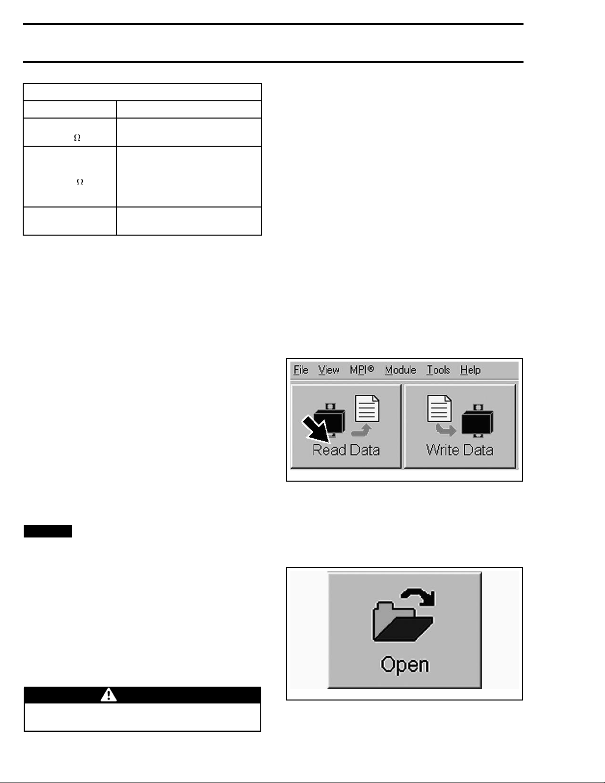
2. In B.U.D.S., click the Read Data button to load
the information from the original ECM.
Removing the ECM
NOTE: If a new ECM is to be installed, first read
the procedures in
REPLACING THE ECM
in this
subsection.
1. Disconnect battery cables.
NOTICE
Always disconnect the BLACK (–)
battery cable first, then disconnect RED (+)
cable.
2. Disconnect ECM connector.
3. Unscrew all retaining screws and pull out ECM.
Installing the ECM
Reverse removal procedure however, pay attention to the following.
1. Reconnect ECM connector.
2. Reconnect battery cables.
WARNIN
Always reconnect the RED (+) battery cable
first, then reconnect BLACK (–) cable.
G
vmr2006-012-100_aen
NOTE: Ke
ECMs. T
comput
ep B.U.D.S. running while replacing
he data will remain stored in the PC
er as long as B.U.D.S. is running.
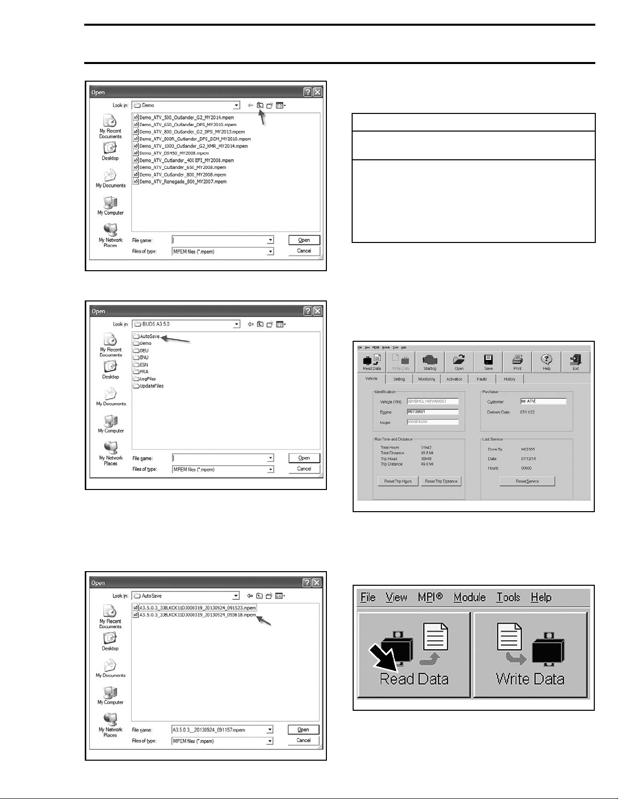
3. Get the Data from the saved .mpem file.
3.1 Click on the Open button.
mmr2009-023-080
3.2 Click once on the Folder Up button in the
open box.
6 vmr2016-423
Page 7
Subsection 01 (ELECTRONIC FUEL INJECTION (EFI))
IMPORTANT: Ensure to use the file that specifically matches the vehicle you are servicing.
NOTE: The file name structure is as follows:
BUDS version_VIN_date read (yyyymmdd)_hour read
(hhmmss).mpem
Example:
A3.5.0.3_3JBLKCK11DJ000319_20130924_093618.mpem
vmr2015-042-010_a
3.3 Double click on the AutoSave folder.
vmr2015-042-011_a
B.U.D.S. ver
VIN = 3JBLKCK11DJ000319
Date file was read = 2013-09-24
Hour file wa
sion = A3.5.0.3
s read = 09h 36m 18s
4. Go to the Vehicle tab and record the following
information.
– Vehicle (V.I.N.) number
– Engine num
ber (without the leading “M”)
– Model number
–Customer.
NOTE: Y
toSave
B.U.D.
3.4 Choose the latest file saved for this specific vehicle.
ou may have to go to another Au-
folder from a previous version of
S.
vmr2008-022-008
5. Remove the original ECM.
6. Insta
ll the new ECM.
7. In B.U.D.S., click the Read Data button to read
the new ECM.
vmr2006-012-100_aen
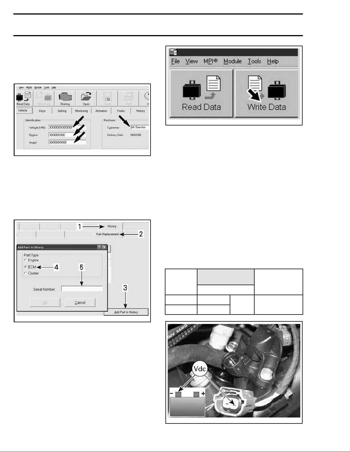
8. Select the Ve hicle tab and enter the informa-
tion you recorded previously.
vmr2015-042-012_a
vmr2016-423 7
– Vehicle serial number
Page 8
Subsection 01 (ELECTRONIC FUEL INJECTION (EFI))
– Engine number (do not enter the “M” at the
beginning of the engine number)
– Enter model number.
– Customer name.
vmr2006-012-100_ben
FUEL INJECTOR
smr2009-030-007_a
VEHICLE TAB
9. Click on the
following tabs:
– History
– Part Replacement
– Add Part in
History.
10. Enter the old ECM serial number in the Add
Part In History window.
tmr2011-022-017_a
ADDING PART IN HISTORY
1. History tab
2. Part Replacement tab
3. Addpartinhistorybutton
4. ECM selection
5. Add ECM serial number here
Refer to the applicable
SYSTEM
subsection for component and connec-
ENGINE MANAGEMENT
tor locations.
Fuel Injector Leak Test
Carry out the
detailed in the
section.
FUEL PUMP PRESSURE TEST
FUEL TANK AND FUEL PUMP
as
sub-
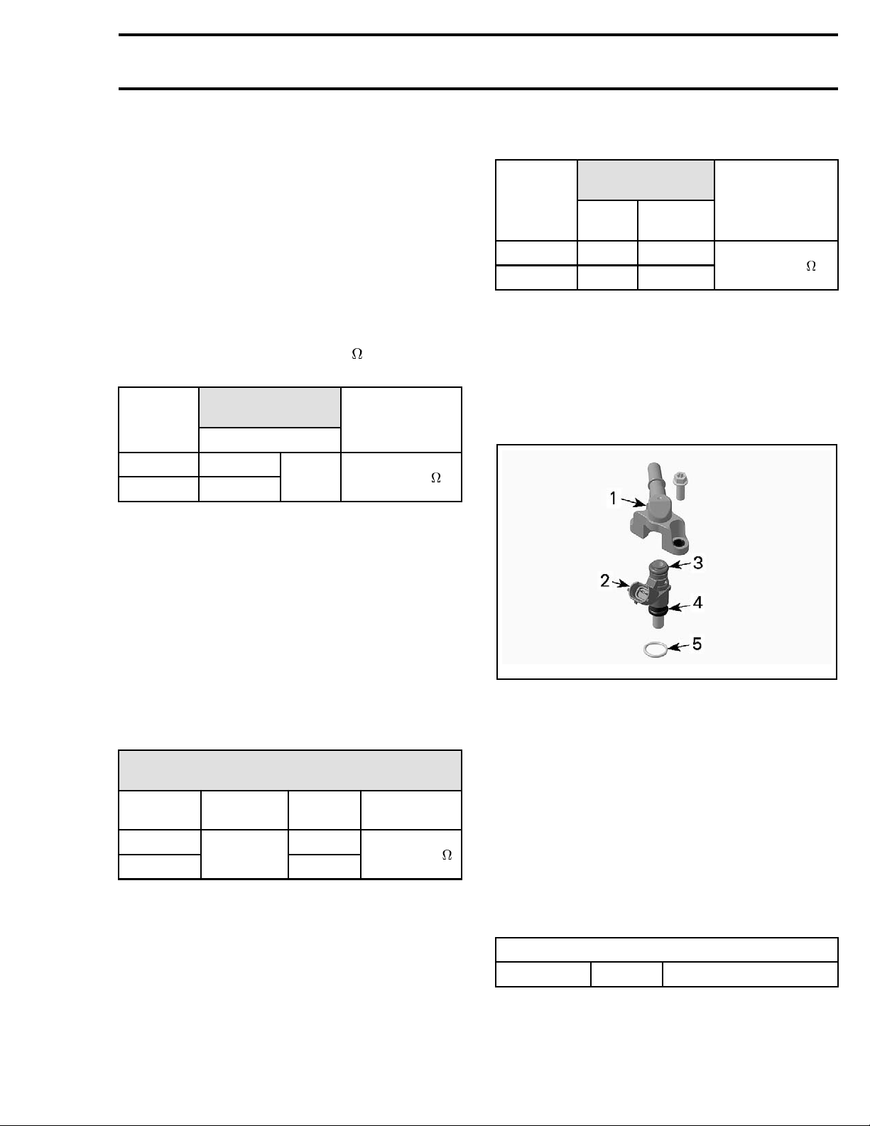
Testing the Fuel Injector Input Voltage
Disconnect the fuel injector electrical c onnector.
Turn on ignition switch.
Set emergency engine stop switch to RUN.
NOTE: Ensure to read voltage before ECM auto-
matically turns off.
Use a multimeter and set it to Vdc. Read voltage.
INJECTOR
CYLINDER
FRONT
REAR
CONNECTOR
WIRE
INJ1-2
INJ2-2
BAT2
(-)
MEASUREMENT
Battery voltage
NOTE: The ECM serial number can be found on
the ECM sticker that also identifies the part number.
11. Click on the OK button.
12. Click on the Write Data button.
8
vmr2006-014-075_a
TYPICAL
vmr2016-423
Page 9
Subsection 01 (ELECTRONIC FUEL INJECTION (EFI))
If supply voltage is not good, check fuse and if
good, perform an
RESISTANCE TEST
If supply voltage is good, perform a
TOR RESISTANCE TEST
INJECTOR POWER CIRCUIT
.
FUEL INJEC-
.
Testing the Injector Power Circuit
Resistance
Check continuity between main relay and injector
as follows:
– Remove main relay.
– Disconnect the fuel injector connector.
– Use a multimeter and set it to
– Read resistance.
INJECTOR
CYLINDER
FRONT
REAR
CIRCUIT
WIRE
INJ1-2
PF1-B2
INJ2-2
If continuity is not good, repair or replace wiring
going to injector.
If continuity is good, perform the
RESISTANCE TEST
.
.
MEASUREMENT
Closeto0
FUEL INJECTOR
Using a multimeter, check resistance value between terminals as follows.
INJECTOR
CYLINDER
FRONT
REAR
GROUND CIRCUI
WIRE
INJ1-1 K4
INJ2-1 L4
ADAPTER
T
MEASUREMENT
ECM
Close to 0
If continuity is not good, repair or replace wiring
going to injector.
If continuity is good, replace the injector.
Removing the Fuel Injector
Remove the fuel rail. Refer to
subsection.
FUEL RAIL
in this
Testing the Fuel Injector Resistance
Disconnect ECM connector.
Install the ECM adapter tool on the ECM connec-
tor.
Connect the fuel injector connector.
Using a multimeter, check resistance value be-
tween terminals as follows.
FUEL INJ E
INJECTOR
FRONT
REAR
CTOR RESISTANCE TEST
AT ECM ADAPTER
FUSE BOX
TERMINAL
PF1-B2
ECM
ADAPTER
K4
L4
RESISTANCE
@ 20°C (68°F)
11.4 - 12.6
If resistance value obtained is incorrect, perform
INJECTOR GROUND CIRCUIT RESISTANCE
an
.
TEST
Testing the Injector Ground Circuit
Resistance
Disconnect the fuel injector connector.
Disconnect ECM connector.
Install the ECM adapter tool on the ECM connec-
tor.
vmr2009-022-001_a
FUEL RAIL
1. Fuel rail
2. Fuel injector
3. Injecto
4. Injector bottom O-ring
5. Manifold O-ring
Pull fue
ASSEMBLY
r top O-ring
l injector out of the fuel rail.
Installing the Fuel Injector
For the i
dure. Pa
Apply a thin film of engine oil to O-rings to ease
insertion in rail.
Install fuel injector with your hand. Do not use any
tool.
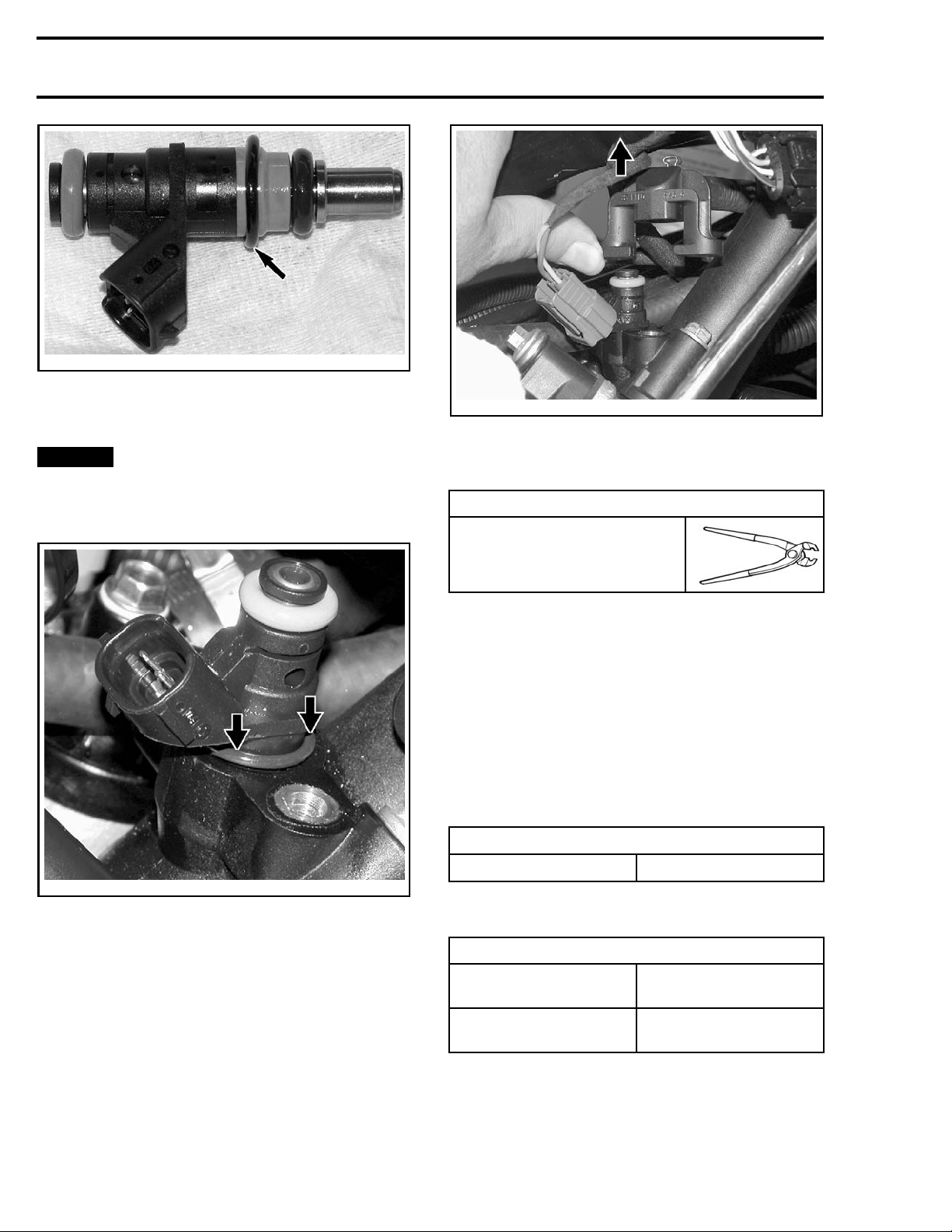
O-RINGS
PositionthemanifoldO-ringoninjectorasinfollowing illustration.
nstallation, reverse the removal proce-
y attention to the following details.
FUEL INJECTOR INSTALLATION
New Lubricate with engine oil
vmr2016-423 9
Page 10
Subsection 01 (ELECTRONIC FUEL INJECTION (EFI))
vmr2006-014-071_a
MANIFOLD O-RING POSITION
Carefully insert injector in manifold paying attention to the manifold O-ring.
NOTICE
Gently push O-ring in evenly all
around while inserting injector. O-ring must
be completely inserted and not visible, before
completing the insertion of the injector.
vmr2006-014-073_a
To disconnect fuel rail from hose, cut clamp on
fuel hose. Refer to
FUEL TANK AND FUEL PUMP
for clamp removal/installation procedures.
REQUIRED TOOL
OETIKER PLIERS (P/N 295
000 070)
NOTE: If fuel rail is removed for access to fuel injector, it is not necessary to cut hose clamp. Only
to replace fuel rail.
Installi
ng the Fuel Rail
For installation, reverse the removal process however, pay attention to the following.
Install new clamps using pliers as per removal (if
fuel rail was replaced).
Apply a t
ease ins
hin film of engine oil to injector O-rings to
ertion in rail.
INJECTOR O-RINGS
Lubricate with engine oil
vmr2006-014-072_a
SERVICE
PRODUCT
Install fuel rail and evenly tighten screws a little at
Firmly push injector until it bottoms out.
Reinstall fuel rail.
FUEL RAIL
Replacing the Fuel Rail
Removing the Fuel Rail
1. Disconnect fuel line to reach the rear injector.
Refer to
FUEL TANK AND FUEL PUMP
subsec-
atimeeachside.
TIGHTENING TORQUE
Service product
Fuel rail retaining screws
LOCTITE 243 (BLUE)
(P/N 293 800 060)
10 N•m ± 1 N•m
(89 lbf•in ±9lbf•in)
NOTE: Activate fuel pump a few times to built
fuel pressure.
tion.
2. Unscrew rail retaining screws.
3. Gently pull rail off by hand.
10 vmr2016-423
Page 11
Subsection 01 (ELECTRONIC FUEL INJECTION (EFI))
WARNING
Perform a fuel pressure test and ensure that
there is no leak. Refer to
FUEL PUMP
.
FUEL TANK AND
THROTTLE CABLE
Removing the Throttle Cable
Remove steering cover.
Remove LH side panel.
Disconnect throttle cable from throttle body. Re-
fer to procedure in this subsection.
Disconnect throttle cable from throttle lever.
Remove throttle cable.
Installing the Throttle Cable
Reverse removal procedure.
Proceed with
in this subsection.
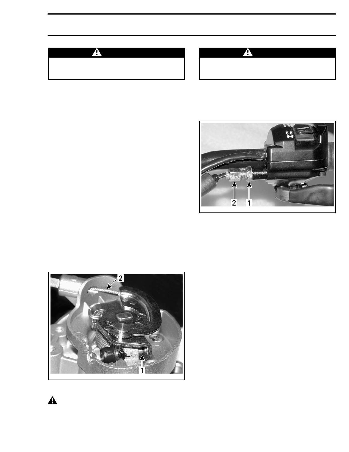
Adjusting the Throttle Cable
Mechanically adjust the throttle cable as follows.
Handlebar and throttle cable must be at their
normal position. Throttle cable routing must have
been performed before adjusting cable.
Activate throttle lever a few times. Make sure
throttle cam of throttle body rests against set
screw without any tension in the cable.
THROTTLE CABLE ADJUSTMENT
WARNING
Make sure idle speed stopper contacts throttle cam when throttle lever is fully released at
handlebar.
If adjustment is needed, proceed with adjuster at
handlebar. Adjust to have 2 mm (.079 in) free-play
at the end of throttle lever. When done, slide back
cable protector over adjuster.
vmr2006-014-067_a
1. Adjuster lock nut
2. Adjuster
Turn handlebar side to side and ensure there is still
free-play in each position.
To ensure
open pos
– Fully depress throttle lever and hold.
– Loosen adjuster lock nut/adjuster until it just re-
leases lever.
–Turnad
again.
– From there, tighten adjuster 1/2 turn (to remove
strain in cable).
– Tighten lock nut.
– Relea
there is no strain in the cable at wide
ition:
juster clockwise until it touches lever
se throttle lever.
vmr2006-014-064_b
1. Contact
2. Free-play here
here
CAUTION If there is no free-play at idle
position, it may cause poor idling and startability problems. Improper cable adjustment
will cause strain on cable and/or damage cable
bracket or throttle lever at handlebar.
vmr2016-423 11
Page 12
Subsection 01 (ELECTRONIC FUEL INJECTION (EFI))
– Check if idle air control valve is loose.
– Check for corroded or damaged connectors.
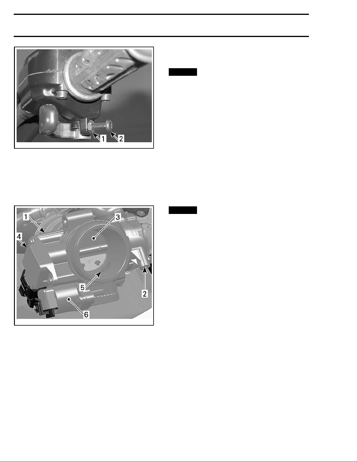
vmr2006-014-068_a
1. Adjuster lock nut
2. Adjuster
Reinstall throttle cable cover.
THROTTLE BODY
Throttle Body Description
NOTICE
The throttle body must be replaced
if idle set screw is loose or worn.
Cleaning the Throttle Body
1. Check throttle body cleanliness using a flashlight. Fully open throttle plate and verify:
– Throttle body bore
– Throttle plate edge.
Look for:
–Dirt
– Oily surfaces
– Carbon and salt deposits on throttle plate and
the s urrounding bore.
2. Clean as necessary.
3. Use a throttle body cleaner such as GUNK INTAKE MEDIC or an equivalent. Refer to manufacturer's instructions.
NOTICE
body cleaner that will not damage O-rings and
EFI sensors.
4. To avoid getting dirt into engine, spray cleaner
on a clean rag then rub rag against throttle plate
and bore. A toothbrush may also be used.
5. Gently open throttle plate and hold fully open to
reach all surfaces.
6. To remove residual dirt, spray cleaner on throttle plate and on bore.
7. Reinstall removed parts.
Only use an appropriate throttle
Removing the Throttle Body
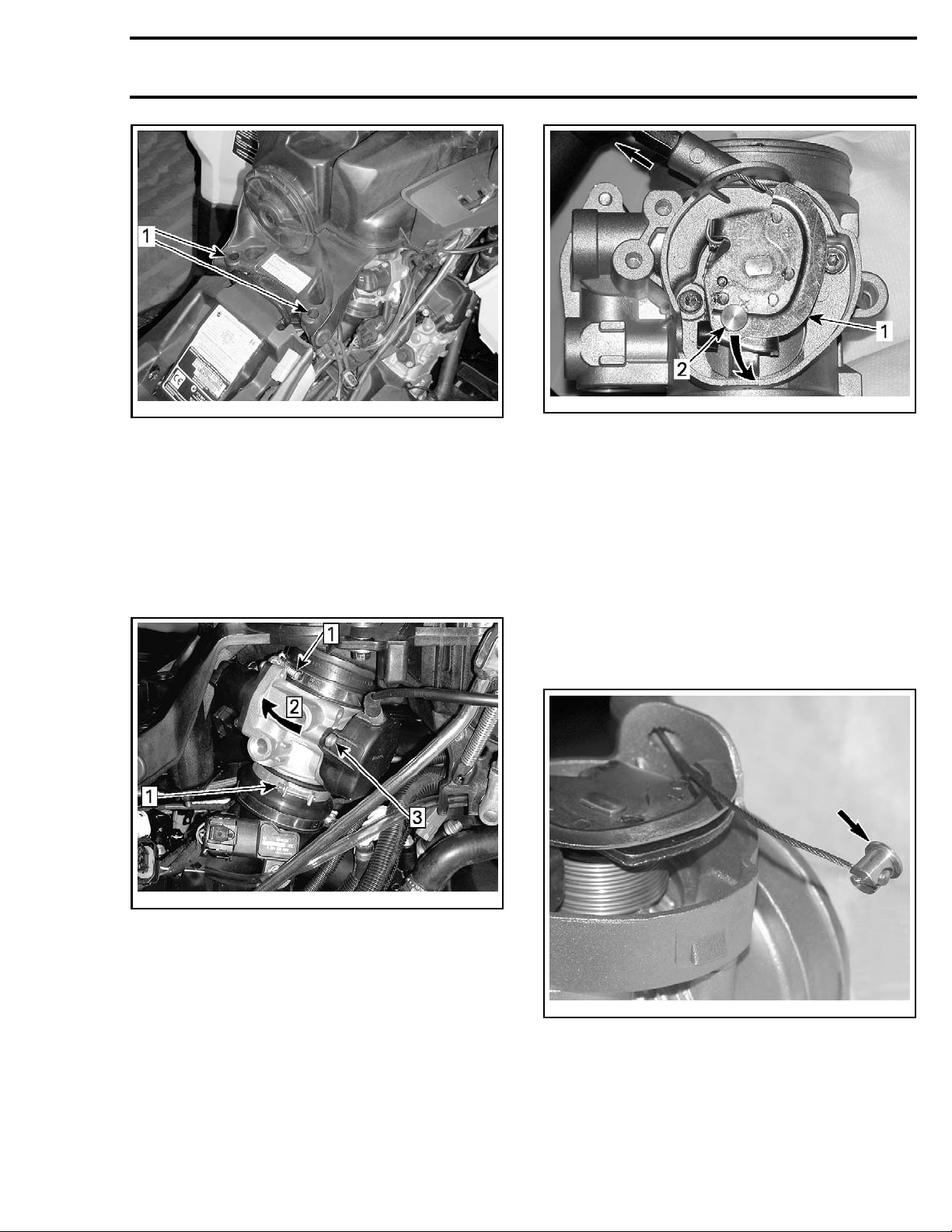
1. Remove the air intake silencer retaining
vmr2006-014-010_a
1. Throt
2. Throttle cable attachment
3. Throttle plate
4. TPS
5. Idle air bypass channel
6. Idle air control valve
Throt
Remove the RH side panel. Refer to
tle body
tleBodyAccess
BODY
sub-
section.
Inspe
cting the Throttle Body
Check that the throttle plate moves freely and
smoothly when depressing throttle lever.
– Chec
k if throttle body idle set screw is loose or
.
worn
– Check if TPS is loose.
12 vmr2016-423
screws.
Page 13
Subsection 01 (ELECTRONIC FUEL INJECTION (EFI))
vmr2012-026-003_a
1. Remove these screws
2. Lift rear of air intake silencer as much as possible and block in this position.
3. Unplug connectors from TPS and IACV.
4. Loosen both throttle body c lamps.
5. Rotate throttle body to gain access to throttle
cable.
6. Remove throttle cable cover.
vmr2006-014-060_b
1. Throttle lever
2. Cable barrel
8. Remove barrel from cable.
9. Pull out throttle cable.
10. Pull out throttle body.
Installing the Throttle Body
Installation of the throttle body is the reverse of
the removal procedure. However, pay attention to
the following.
Temporarily install throttle body into position.
Properly install cable barrel to throttle cable end.
vmr2012-026-004_a
1: Loosen
Step
Step 2: Rotate
Step 3: Remove
7. Rota
te throttle lever and pull out cable barrel.
vmr20
06-014-063_a
Hook cable to throttle lever.
vmr2016-423 13
Page 14
Subsection 01 (ELECTRONIC FUEL INJECTION (EFI))
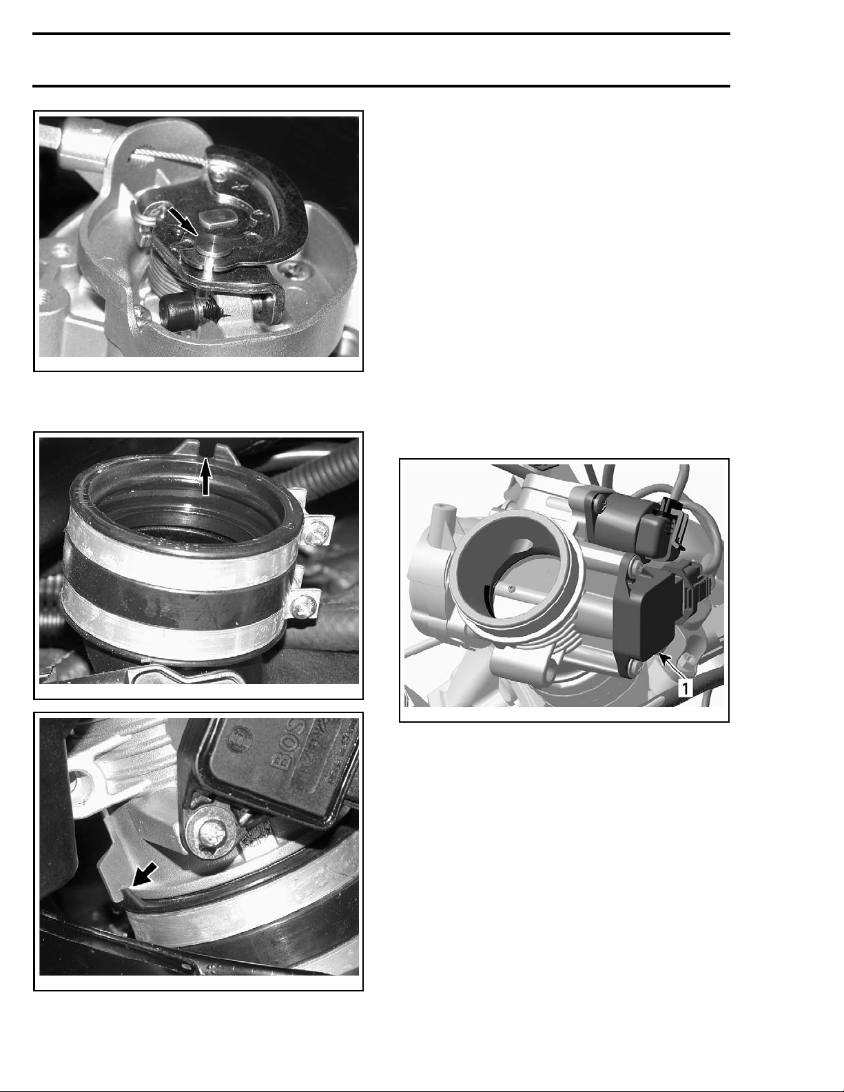
Tighten clamps.
– Check throttle cable adjustment. Refer to
THROTTLE CABLE
– If throttle body was replaced, perform the
CLOSED THROTTLE AND IDLE ACTUATOR
RESET
cedures in this subsection.
THROTTLE POSITION SENSOR
(TPS)
and the
in this subsection.
IACV CALIBRATION
. See pro-
vmr2006-014-064_a
Rotate throttle body into position and ensure to
index throttle body tab with boot notch.
6-014-065_a
vmr200
Refer to the applicable
SYSTEM
subsection for component and connec-
ENGINE MANAGEMENT
tor locations.
General
The throttle position sensor (TPS) is a potentiometer that sends a signal to the ECM which is proportional to the throttle plate angle.
vmr2008-022-010_b
1. Throttle position sensor (TPS)
The ECM
tainin
FAULT C
may generate several fault codes per-
gtotheTPS.Referto
ODES
subsection for more information.
DIAGNOSTIC AND
TPS Access
Remove
sectio
the RH side panel. Refer to
n.
Loosen both throttle body clamps.
Rotate throttle body to gain access to TPS.
vmr2006-014-65_a
14 vmr2016-423
BODY
sub-
Page 15
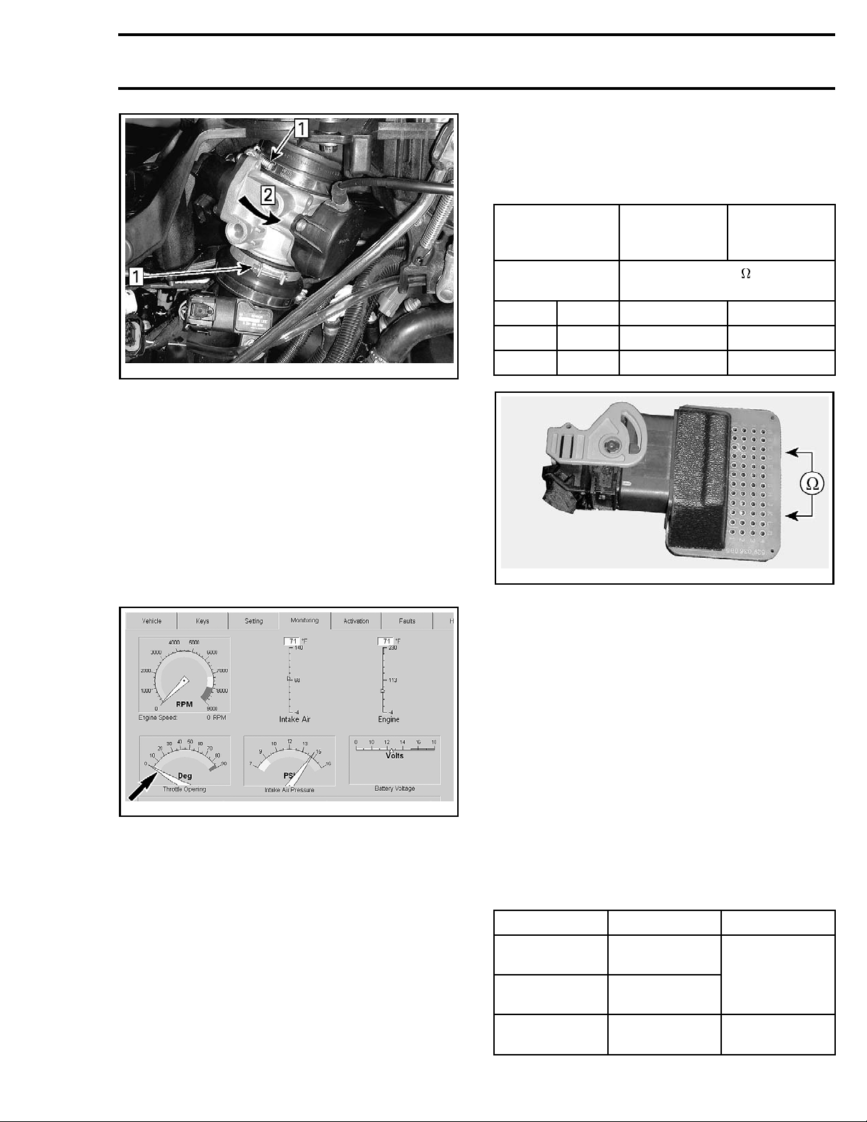
Subsection 01 (ELECTRONIC FUEL INJECTION (EFI))
Ensure TPS is connected to wiring harness.
Disconnect the ECM connector.
Using the ECM adapter tool and a multimeter,
check resistance values.
vmr2012-026-004_b
Step 1: Loosen
Step 2: Rotate
Testing the TPS Wear
IMPORTANT: Prior to testing the TPS, ensure
that mechanical components of throttle body are
checked.
While engine is not running, activate throttle and
pay attention for smooth operation without physical stops of the cable.
Using the B.U.D.S. software, use the Throttle
Opening display under Monitoring.
ECM ADAPTER
PIN
G3 G2
G2
G3
vmr2008-0
22-005_a
A1 1800-2200 1800-2200
A1 2200-3100 800-1200
THROTTLE
IDLE
POSITION
RESISTANCE (
900-1600 2600-3100
WIDE OPEN
THROTTLE
POSITION
) @ 20°C
(68°F)
NOTE: The resistance value should change
smoothly and proportionally to throttle movement. Otherwise, replace TPS.
If resista
nce values are correct, perform the
INPUT VOLT
AGE TEST
below.
TPS
If resistance values are incorrect, check wiring
harness. If wiring is faulty, repair/replace. If
wiring is good, replace TPS.
Reconnect ECM connector.
Testing the TPS Input Voltage
vmr2006-014-083_aen
Slowly and regularly depress the throttle. Observe the needle movement. It must change
gradually and regularly as you move the throttle. If the needle “sticks”, bounces, suddenly
drops or if any discrepancy between the throttle
movement and the needle movement is noticed,
it indicates that the TPS needs to be replaced or
the computer used may be too slow to transfer
data fast enough for real time display.
Testing the TPS Resistance
Ensure correct throttle cable adjustment. Refer to
THROTTLE CABLE ADJUSTMENT
tion.
vmr2016-423 15
in this subsec-
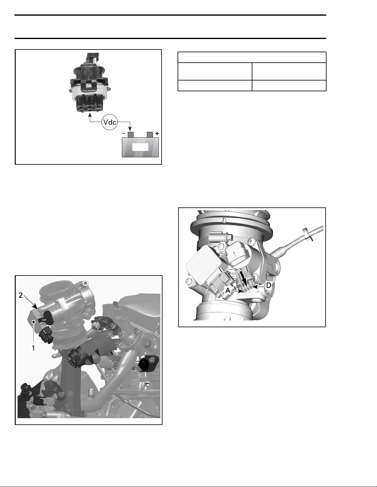
Disconnect connector from TPS.
Turn ignit
ion key ON.
Set emergency engine stop switch to RUN.
Check the voltage readings from harness connec-
tor as follows.
ENGINES CONNECTION VOLTAGE
570 and 650
850 and 1000R
All
Pin 1 with
battery ground
Pin 3 with
battery ground
Pin 2 with
battery ground
5.0 V
0V
Page 16
Subsection 01 (ELECTRONIC FUEL INJECTION (EFI))
BAT
smr2005-056-016_a
If voltage t
ness. If wi
THE ECM
If voltage test is good, everything is in order (assuming resistance test was performed).
Replacing
Refer to
access to TPS.
Unplug connector from TPS.
Loosen TPS
Remove TPS.
est is not good, check/repair wiring har-
ring tests good, refer to
REPLACING
.
the TPS
TPS ACCESS
retaining screws.
in this subsection to gain
TIGHTENING TOR
Service product
TPS retaining screws
Perform the Cl
Reset procedu
AND IDLE ACTUA
osed Throttle And Idle Actuator
re. Refer to
TOR RESET
IDLE AIR CONTR
Refer to the applicable
SYSTEM
subsection for component and connec-
OL VALVE (IACV)
ENGINE MANAGEMENT
QUE
LOCTITE 243 (BLUE)
(P/N 293 800 060
3N•m (27lbf•in)
)
CLOSED THROTTLE
in this subsection.
tor locations.
An idle air control v alve with good resistance
measurement can still be faulty. It is also possible that a mechanical failure occurs which is
not detectable without measuring the air flow.
Replacing the IACV may be necessary as a test.
vmr2015-042-004_a
IACV Access
Refer to
access to IACV.
TPS ACCESS
in this subsection to gain
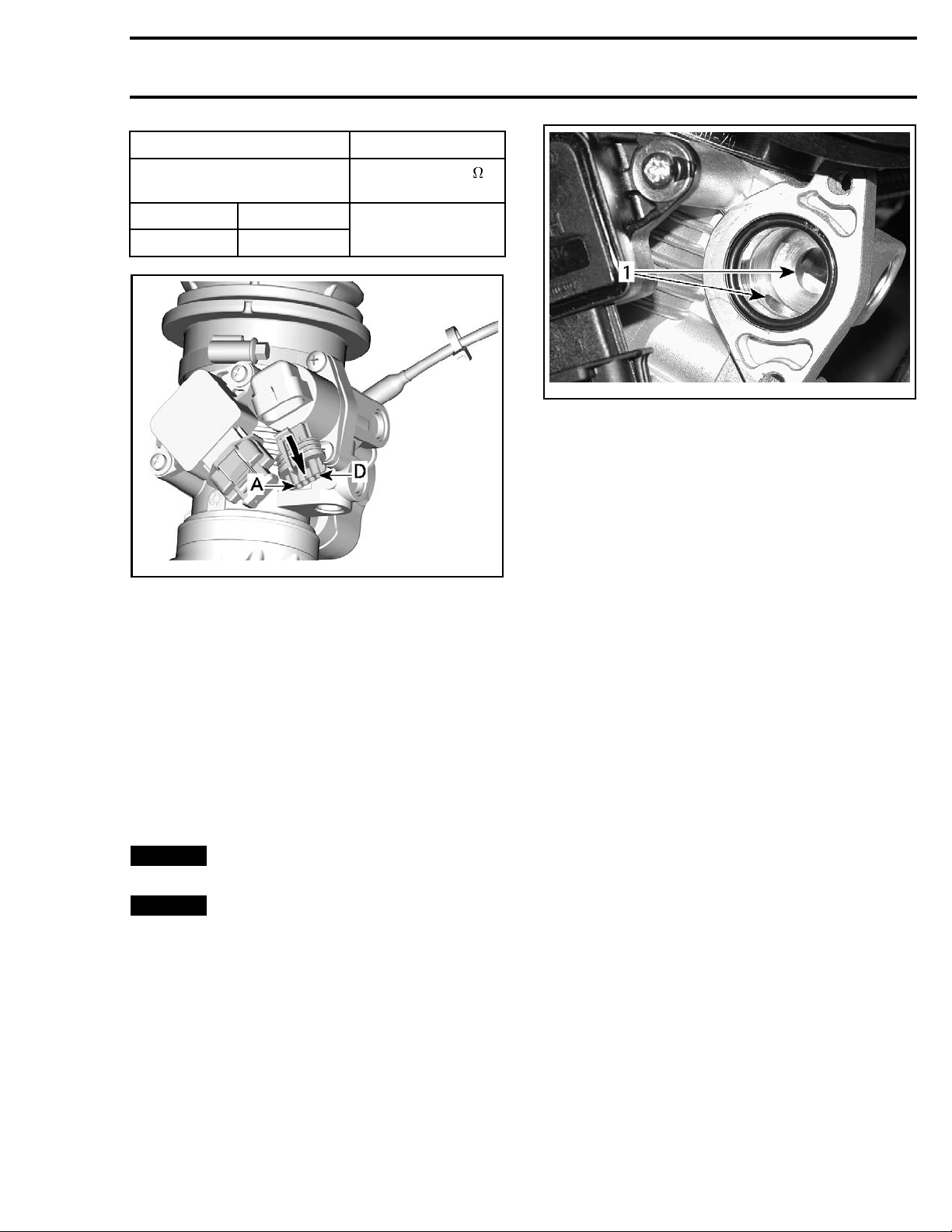
Testing the IACV Resistance
Disconnect IACV from the wiring harness.
Using a multimeter, check the resistance in both
windings.
Check the resistance between pins as shown.
6-012-004_c
vmr200
1. TPS
2. Screws
ll the new TPS and tighten retaining screws
Insta
to spe
16 vmr2016-423
cification.
Page 17
Subsection 01 (ELECTRONIC FUEL INJECTION (EFI))
IDLE AIR CONT R O
PIN
AD
B
vmr2015-042-004_a
LVALVE
C
MEASUREMENT
RESISTANCE (
@ 20°C (68°F)
50 ± 5
)
If the resistance of any winding is not good, replace the idle air control valve.
If resistance test of valve windings is good, check
continuity of circuits C4, D3, D4, E4. If not good,
check/repair wiring/connectors.
Inspecting the IACV Visual
NOTE: Make sure the ignition key is turned off
during the following procedure.
Remove Idle air control valve from throttle body.
Check the piston and bypass channel for dirt/de-
posits which can cause a sticking piston.
NOTICE
OFF, while the idle air control valve is removed.
NOTICE
of the idle air control valve when it is dismounted. Also do not move the piston by
hand. The drive screw is very sensitive and
may be destroyed.
Always keep the ignition key turned
Do not try to operate the piston
vmr2006-014-085_a
1. Clean bore from contamination
Clean all remaining parts and i nstall the idle air
control valve on the throttle body.
Proceed with the Closed Throttle and Idle Actu-
ator Resetand the
IACV CALIBRATION
. See pro-
cedures in this subsection.
IACV Calibration
The IACV calibration is required to avoid a potential erratic or frozen RPM needle.
1. Start the vehicle to increase engine tempera-
ture.
2. Let engine run at idle until the cooling fan per-
formed a complete cycle (ON/OFF).
3. When the cycle is done, turn ignition key to OFF
position.
4. The calibration is completed.
CRANKSHAFT POSITION
SENSOR (CPS)
Refer to applicable
subsection for component and connector lo-
TEM
cations.
NOTE: Take into account that a CPS fault can be
triggered by bent or missing encoder wheel teeth.
First check fault codes using B.U.D.S., then check
the encoder wheel teeth condition if necessary.
Refer to
MAGNETO AND STARTER
ENGINE MANAGEMENT SYS-
subsections.
Using a part cleaner, clean idle bypass in throttle
body from contamination then blow compressed
air to dry it.
CPS Access
Remove the RH side panel. Refer to
BODY
sub-
section.
To reach the CPS connector, remove protector
from engine.
Testing the CPS Resistance
Disconnect the ECM connector.
vmr2016-423 17
Page 18
Subsection 01 (ELECTRONIC FUEL INJECTION (EFI))
Install ECM adapter tool on the ECM connector.
Using a multimeter, measure resistance as per ta-
ble.
ECM ADAPTER MEASUREMENT
PIN
D1 E1 700 - 900
RESISTANCE
@ 20°C (68°F)
If resistance value is incorrect, check or repair the
connectors and the wiring harness between ECM
connector and the CPS. If resistance value is still
incorrect, replace CPS.
Replacing the CPS
Refer to
CPS.
Disconnect CPS connector and cut harness locking tie (if applicable).
Remove CPS retaining screw and pull up on CPS
to remove it.
CPS ACCESS
in this subsection to reach
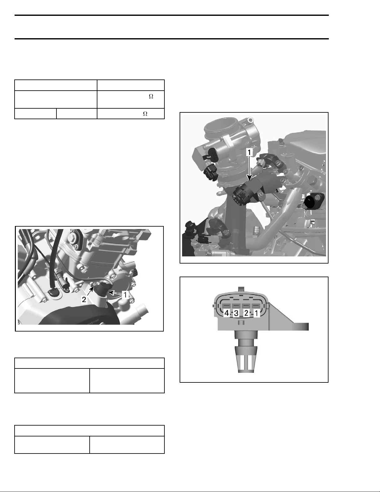
MANIFOLD ABSOLUTE
PRESSURE AND TEMPERATURE
SENSOR (MAPTS)
Refer to applicable
subsection for component and connector lo-
TEM
cations.
ENGINE MANAGEMENT SYS-
vmr2016-130-001_a
1. CPS
2. Retaining screw
Lubricate O-ring of C PS.
O-RING
XPS SYNTHETIC
Service product
GREASE
(P/N 293 550 010)
Install new CPS and secure harness with a new
locking tie (as applicable).
Tighten CPS retaining screw to specification.
TIGHTENING TORQUE
CPS retaining screw
10 N•m ± 1 N•m
(89 lbf•in ±9lbf•in)
vmr2006-012-004_d
1. Manifold absolute pressure and temperature sensor (MAPTS)
vmr2015-042-006_a
NOTE: This sensor is a multifunction device.
MAPTS Access
Remove the RH side panel. Refer to
section.
BODY
sub-
MAPTS Pressure Function
Before the engine is started, when power is applied to the system, the sensor measures the
ambient air atmospheric pressure. The ambient
pressure is, at that moment, stored in the ECM.
18 vmr2016-423
Page 19
Subsection 01 (ELECTRONIC FUEL INJECTION (EFI))
Thereafter, once the engine is started, it measures the air pressure in the intake manifold at
operating RPMs.
The sensor must be correctly installed on intake
manifold. Otherwise, the MAPTS could generate
a fault code for an unexpected s ensor range at idle
when it reads the atmospheric pressure. If this
is the case, remove sensor and check for oil or
dirt on its end and if problem persists, check throttle plate condition/position and the wiring harness.
Perform the following tests.
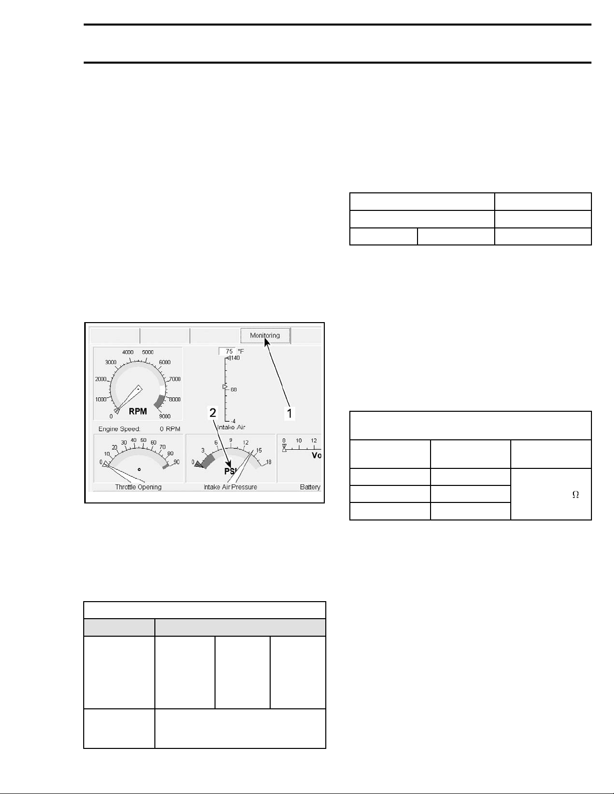
MAPTS Pressure Function Quick Test
1. Connect vehicle to the latest applicable
B.U.D.S. software version.
2. In B.U.D.S., click the following:
– Monitoring tab
– ECM tab.
Testing the MAPTS Input Voltage
Check the voltage output from ECM to the pressure sensor.
1. Turn ignition key ON.
2. Set emergency engine stop switch to RUN.
3. Remove electrical connector from MAPTS.
4. Using a multimeteras per following table.
MAPTS CONNEC
PIN VOLTAGE
1
TOR
35Vdc
MEASUREMENT
If voltage test is good, replace the MAPTS.
If voltage test is not good, carry out the
MAPTS
CIRCUIT CONTINUITY TEST (PRESSURE FUNC-
.
TION)
Testing the M APTS Circuit Continuity
(Pressure Function)
1. Disconnect the ECM connector.
2. Install the ECM adapter tool on the ECM connector.
3. Using a multimeter, check continuity of the following circuits.
-026-150_b
vmr2012
1. Monitoring tab
2. MAPTS pre ssure reading
3. Look fo
readin
r and take note of the MAPTS pressure
g while the engine is stopped.
4. Perform the same test with a new MAPTS and
compare both readings.
Values have to be within ± 3.4 kPa (.5 PSI).
MAPTS PRESSURE FUNCTION QUICK TEST
RESULT SERVICE ACTION
it
Circu
NO
READING
VALU E IS
OUT OF
RANGE
continuity
test of
MAPTS
pressure
function
MAPTS
input
ge
volta
test
Replace MAPTS
Repair or
replace
wiring
MAPTS CIRCUIT CONTINUITY TEST
(PRESSUR
ECM
ADAPTER
A1 Pin 3
F2 P i n 4
G2
E FUNCTION)
MAPTS
CONNECTOR
Pin 1
RESISTANCE
VALU E
Close to 0
If resistance is not within specification, repair or
replace the wiring harness between ECM connector and the MAPTS.
MAPTS Temperature Function
The sensor monitors the temperature in the intake
manifold.
Testing the MAPTS Temperature Function
1. Connect vehicle to the applicable B.U.D.S. software version.
2. In B.U.D.S., click the following:
– Monitoring tab
– ECM tab.
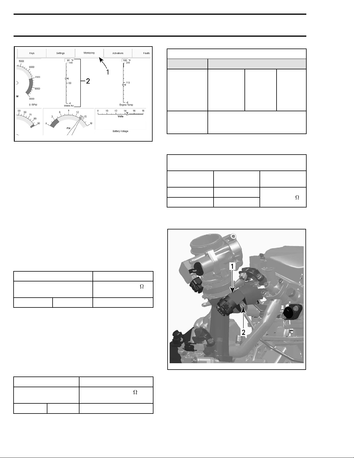
3. Look for the Intake Air temperature reading
while the engine is stopped.
vmr2016-423 19
Page 20
Subsection 01 (ELECTRONIC FUEL INJECTION (EFI))
vmr2016-045-001_a
1. Monitoring tab
2. MAPTS temperature reading
4. Perform the same test with a new MAPTS and
compare both readings.
If the engine MAPTS temperature reading is significantly different than the new MAPTS, replace
it.
NOTE: Both sensors must feel the same ambient
air temperature.
If there is no reading, carry out a
TANCE TEST (TEMPERATURE FUNCTION)
MAPTS RESIS-
.
MAPTS TEMPERAT
RESULT SERVICE ACTION
NO
READING
INCORRECT
RESISTANCE
VALU E
URE SENSOR TEST RESULTS
Circuit
Continuity
Test o f
MAPTS
Temperature
Function
MAPTS
Input
Voltage
Tes t
Replace MAPTS
Testing the M APTS Circuit Continuity
(Temperature Function)
MAPTS CIRCUIT CONTINUITY TEST
(TEMPERATURE FUNCTION)
ECM
ADAPTER
G2
F3 P i n 2
MAPTS
CONNECTOR
Pin 1
RESISTANCE
VALU E
Close to 0
Replacing the MAPTS
Repair or
replace
wiring
Testing the MAPTS Resistance (Temperature
Function)
Disconnect the connector from the MAPTS.
Using a multimeter, check the resistance of the
sensor itself as shown.
MAPTS MEASUREM
PIN
1
2 2280 - 2740
RESISTANCE
@ 20°C (68°F)
ENT
If resistance is not within specification, replace
the MAPTS.
If resistance tests good, reconnect the MAPTS
and disconnect the ECM connector.
Install the ECM adapter tool on the ECM connector.
Using a multimeter, recheck resistance value as
per following table.
ECM ADAPTER MEASUREMENT
RESISTANCE
@ 20°C (68°F)
2280 - 2
740
F3
PIN
G2
vmr2006-012-004_e
1. MAPT
2. Retaining screw
S
Disconnect MAPTS connector and remove the
MAPTS.
Install new MAPTS as per following table.
20 vmr2016-423
Page 21
Subsection 01 (ELECTRONIC FUEL INJECTION (EFI))
TIGHTENING TO R
Service product
MAPTS retaining screw
QUE
LOCTITE 243 (BLUE)
(P/N 293 800 060
6N•m± 0.7N•m
(53 lbf•in ±6l
)
bf•in)
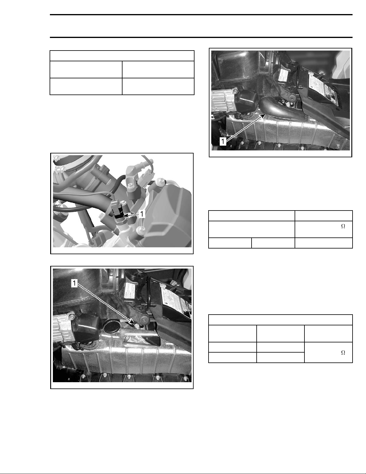
CTS (COOLANT TEMPERATURE
SENSOR)
Refer to appr
SYSTEM
tor locatio
subse
ns.
opriate
ction for component and connec-
ENGINE MANAGEMENT
vmr2012-026-006_a
TYPICAL
1. Pull out
Testing the CTS Resistance
1. Disconnect the ECM connector.
2. Using the ECM adapter tool and a multimeter,
check resistance values.
ECM ADAPTER MEASUREMENT
PIN
RESISTANCE (
@ 20°C (68°F)
)
vmr2016-130-002_a
1. CTS
vmr2012-026-007_a
LH SIDE OF VEHICLE
1. CTS
CTS Access
Remove the LH panel. Refer to
Remove the CVT duct.
BODY
subsection.
C3
F4 2280 - 2736
If resistance value is incorrect, check wiring continuity between ECM connector and the CTS. Re-
CTS CIRCUIT CONTINUITY TEST
fer to
in this sub-
section.
Testing the CTS Circuit Continuity
1. Disconnect connector from CTS and check the
circuit continuity.
CTS CIR
ECM
ADAPTER
Pin F4 Pin 1
Pin C3
CUIT CONTINUITY TEST
CTS
CONNECTOR
Pin 2
RESISTANCE
VALU E
Close to 0
If resistance value is incorrect, repair or replace
wiring or connectors/terminals.
If resistance test is good, replace the CTS.
Replacing the CTS
1. Refer to
reach CTS.
2. Remove heat shield over exhaust pipe to expose CTS. Refer to
tion.
CTS ACCESS
EXHAUST SYSTEM
in this subsection to
subsec-
vmr2016-423 21
Page 22
Subsection 01 (ELECTRONIC FUEL INJECTION (EFI))
vmr2012-026-008_a
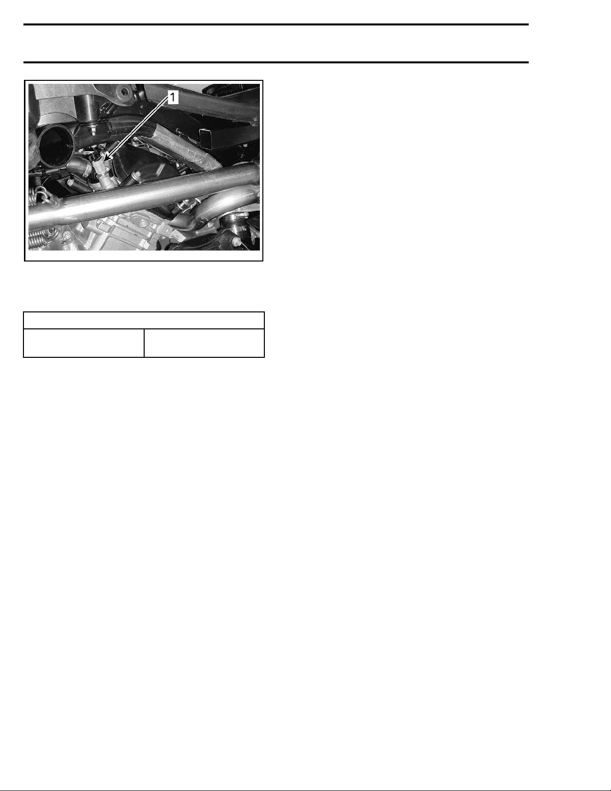
1. CTS
3. Disconnect CTS connector and remove CTS.
4. Install the new CTS and torque as specified.
TIGHTENING TORQUE
CTS
16 N•m ± 2 N
(142 lbf•in ±18lbf•in )
•m
5. Reinstall remaining removed parts.
6. Refill and bleed the cooling system. Refer to
COOLING SYSTEM
subsection.
22 vmr2016-423
 Loading...