

Page 1
Instruction Manual
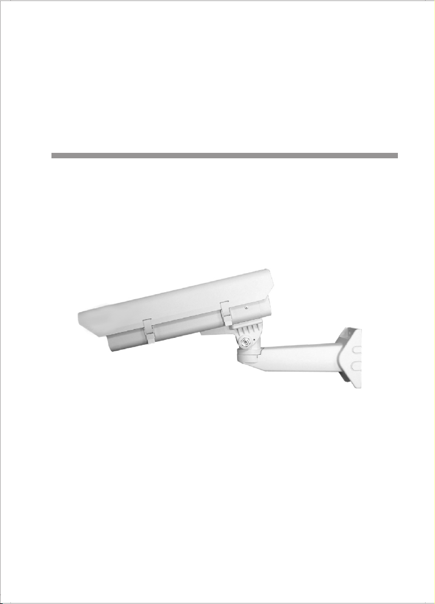
WEATHERPROOF CAMERA
HOUSING
Please read this manual thoroughly before use, and keep it handy for future reference.
Page 2
CAUTION
C A U T I O NC A U T I O N
RISK OF ELECTRIC SHOCK
DO NOT OPEN
CAUTION: TO REDUCE THE RISK OF ELECTRIC SHOCK,
DO NOT REMOVE COVER (OR BACK).
NO USER-SERVICEABLE PARTS INSIDE.
REFER SERVICING TO QUALIFIED SERVICE PERSONNEL.
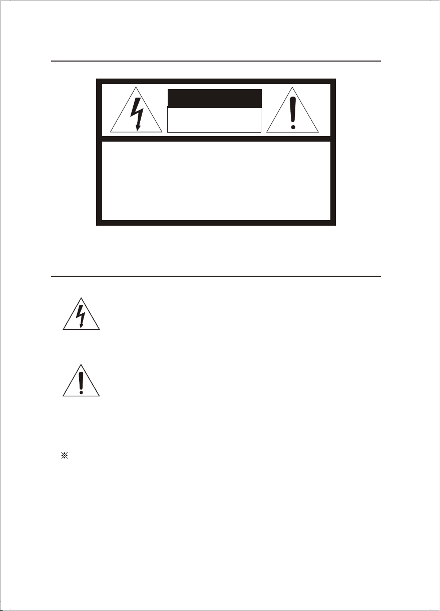
EXPLANATION OF GRAPHICAL SYMBOLS
The lightning fl as h w it h a rr ow he ad symbol, within an equilateral
triangle, is int en de d to alert the us er to the presence of
uninsulated "dangerous vo lt ag e" w it hi n th e pr od uc t' s en cl osure
that may be of sufficient mag nit ude to con sti tu te a ri sk of
The exclamation point within an equilater al triangle is intended to
alert the user to the p resence of importan t operating and
m a i n t e n a nc e ( s e r v i c i n g ) i n s t r u c t i o n i n t h e l i t e r a t u r e
accompanying the product.
FIELD INSTALLATION - This installation should be made by a qualified
service person and should conform to all local codes.
- 2 -
Page 3
1. DESCRIPTIONS
The camera housing series are stylish and functionally designed enclosures for 1/2
and 1/3 CCD cameras with fixed focal length or small zoom lenses.
This manual describes how to assemble the housing and its optional components,
affix the camera and mount the assembly to a suitable surface.
2. PRODUCT FEATURES
. For 1/2" or 1/3" format CCD cameras
. All aluminum construction . Cable feedthrough
. Side opening for easy access . IP 66 rated
. Adjustable mounting track . Optional sunshield component
. Designed for indoor/outdoor applications; for use with fixed mount or pan/tilt
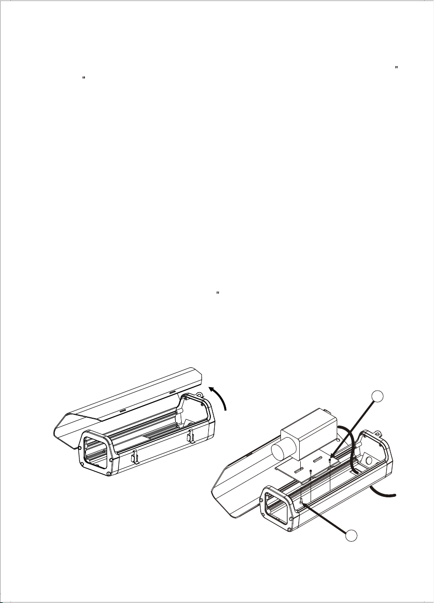
3. CAMERA MOUNTING
1. Unlatch lid and open.
2. Loosen the screws (A) in the bottom of the enclosure and remove the camera sled
from the rail.
3. Mount the camera to the sled with1/4 -20 UNC screw (B) that are provided in the
parts bag.
4. Make the electrical terminations ensuring that they are electrically safe when
connected to the terminal strip.
5. Close the lid and latch.
- 3 -
Open
A
B
Page 4

4. WALL BRACKET MOUNTING
1. Insert the cable through the rubber sealing pad and make all of the necessary
electrical connections as described in the instructions that accompanied the camera.
Be sure that the rubber sealing pad may be to use the bore a hole with a gimlet or
knife.
2. Use fasteners of appropriate size and type to attach the bracket to the wall surface.
Position the housing so that it allow for viewing of the selected area.
3. Adjust the movable arm of the wall bracket to attain the desired position.
One it is in place, tighten the bolt located at the pivot point of the movable arm.
4. If applicable the cable out, remove the knockout on the wall bracket mounting.
Rubber
Sealing Pad
3
3
- 4 -
2
4
Page 5

5. HEATER AND BLOWER KIT INSTALLATION
2
3
1
2
4
6
7
5
2
HEATER KIT INSTALLATION
1
2
3
4
5
6
7
Heater:
Heater: AC24V/ 20W
Screw machine:
PCB & thermostat assembly (Heater only)
PCB & thermostat assembly
Fan: 24VDC (AC rectified), 19CFM
Flat washer M3
Screw machine: Pan head PC3x30 (24VDC Fan only)
1
2
HEATER & BLOWER KIT INSTALLATION
DESCRIPTIONITEM Q'TY
AC110V~230V/ 20W
Flat washer head NPC3x6
1
1
4
1
(Heater and blower) AC24V
(Heater and blower) AC110V ~ 230V
1
1
1
2
2
- 5 -
Page 6

6. WIRING DIAGRAM
* HEATER
Ground
Power
Supply Ou tp ut
Out
to Heater
* HEATER AND BLOWER
24Vdc O ut
to Blow er
24Vac Po wer
Suppl y Ou tput
24Vac Ou t
to Heat er
(Grou nd )
Groun d
J2
J1
Ground
Power
J3J4
AC24V /AC120V /AC230V Heater PCB
(B+)
J3
J6
J4 J5
24 Vac
Supply In pu t
J1
Groun d
24Vac Po wer
Suppl y In put
12 Vd cOut
to Bl ower
(Gr ound)
Gro und
Sup ply Out put
Pow er
Out
to He ater
(B+ )
FAN
AC IN
HT
120/230 Vac
POWER : Use of Listed Class 2 power source.
- 6 -
Gro und
Sup ply Inp ut
Pow er
Page 7

7. BLOWER (OPTIONAL)
Powe r Supply: 24 Vac or 120/230 Vac
Powe r Consumption: 3.4W
Blow er ON: t C > 35 C + /-3 C
Blow er OFF: t C < 20 C + /-3 C
o o o
o o o
T F > 95 F +/-5 F
o o o
8. HEATER (OPTIONAL)
Powe r Supply: 24 Vac or 120/230 Vac
Powe r Consumption: 20W
Heat er ON: t C < 5 C +/- 3 C
Heat er OFF: t C > 15 C +/- 3 C
o o o
o o o
T F < 41 F +/- 5 F
o o o
9. SUNSHIELD INSTALLATION
Mount the sunshield from the top of the housing. Align the hole and secure using the
small four philips panhead screws.
Philips Panhead
screws M4 x 8 (4x)
- 7 -
Page 8

10. SPECIFICATIONS
Camera Housing
Maximum Camera
and lens Size
Wall Bracket
Dime ns ion (WxHxL) 3.2 x 5.5 x 12.4 in . (8 0 x 140 x 315 mm)
Weight 1.70 lb (0.77 k g)
Pan Adj us tment 360
Til t Adjustment 70
Lock in g Method Friction contr ol led through bolt tigh te ning
Wal l Mounting Method 4 hol es f or fasteners of a suita bl e size & type.
Mount to a sec ur e solid surface.
Accepts camera & lens combinations
(including BNC connector) up to:
11.5" L x 3.5" W x 2.5" H
(29.21 cm x 8.89 cm x 6.35 cm)
.11-inch (3.0 mm) thick tempered glassWindow Size
2.42" H x 2.65" W (6.15 cm x 6.75 cm)
Die-cast, extruded, and sheet aluminumConstruction
Light-gray polyester powder coatFinish
Removable camera sled with Camera Mounting
Adjustable height
Two (2) 1/ 4 -20 tapped holesHousing Mounting
Located at rear of housingRear Locking
available for security lock
Unit
ShippingWeight
3.03 lb (1.38 kg)2.70 lb (1.23 kg)
o
o
4.76
(12.1)
2.65
(6.75)
0.96
(2.5)
7.51
(19.10)
14.17
(36.00)
12.59
(32.00)
2.0
(5.00)
1/4-20, 2X
20.3
(51.5)
2.42 3.68
(9.35)(6.15)
Unit: in ch(c m)
Printed In Korea 50301547C
9.1
(23.15)
 Loading...