

Page 1
Section 07 CHASSIS
Subsection 03 (DYNAMIC POWER STEERING (DPS))
DYNAMIC POWER STEERING (DPS)
SERVICE TOOLS
Description Part Number Page
FLUKE 115 MULTIMETER ............................................................ 529 035 868 ......................................... 520
PITMAN ARM JIG ................................................. ........................ 529 036 225 ................................. 532, 534
PITMAN ARM PULLER ................................................................. 529 036 227 ......................................... 533
POSITIONING ADAPTOR .............................................................. 529 036 2 30 ......................................... 532
SERVICE PRODUCTS
Description Part Number Page
LOCTITE 767 (ANTISEIZE LUBRICANT) ....................................... 293 800 070 ......................................... 534
XPS SYNTHETIC GREASE.......... ................................................... 293 550 010 ......................................... 527
GENERAL
SYSTEM DESCRIPTION
(FEATURES)
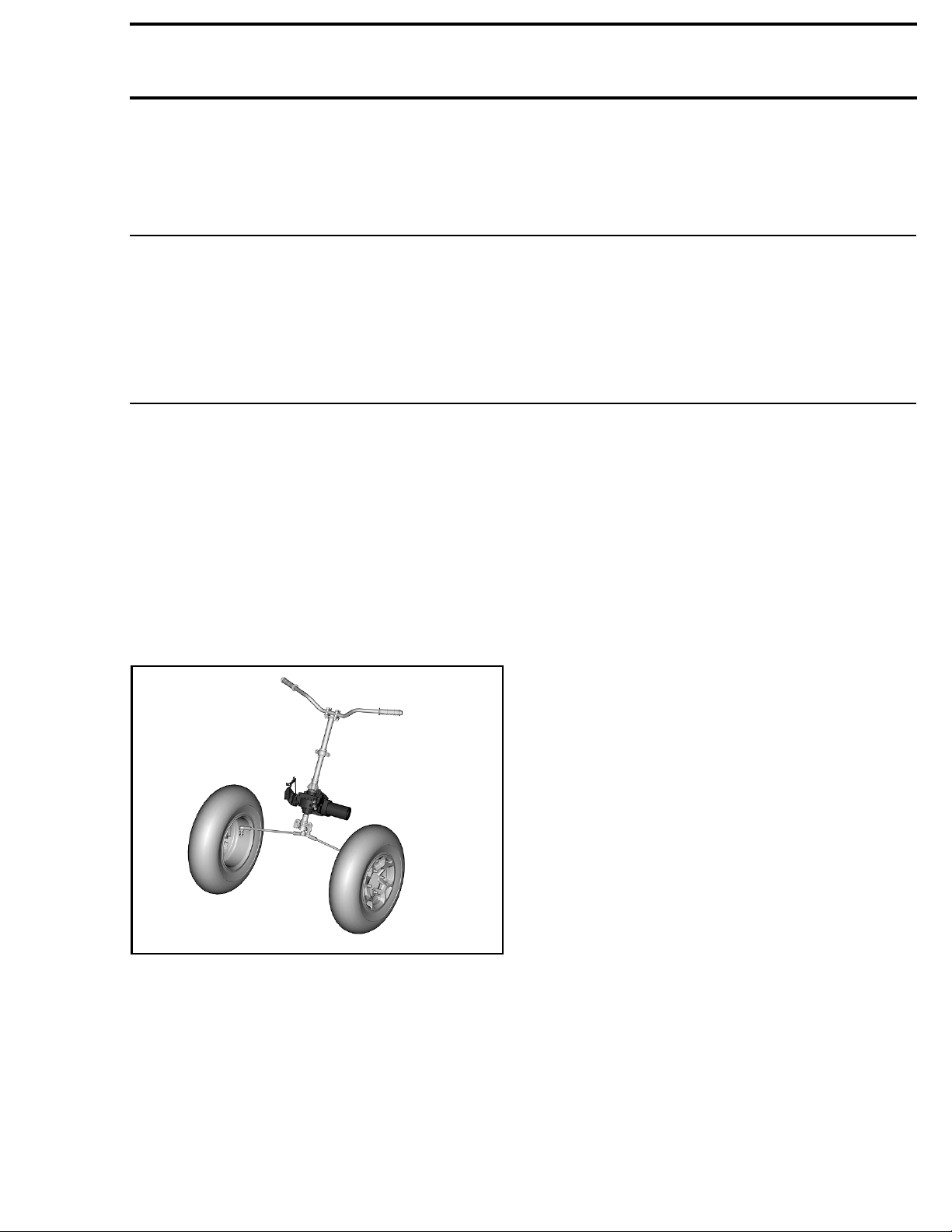
The Dynamic Power Steering (DPS) provides
a computer controlled, variable power assist,
achieved by an electric motor to optimize the
amount of steering input required by the rider.
vmr2010-003-014_a
1. Dynamic power stee
The DPS system uses the following parameters to
determine how much steering assist it provides:
–EngineRPM
– Battery/electric
– Vehicle speed
– DPS shaft torque sensor input.
The amount of steering assist provided is dependent on the handlebar effort (steering torque),
electrical power available, and vehicle speed.
ring unit (DPS)
al system voltage
The greater the handlebar effort (torque), the
greater the assist will be.
The slower the vehicle speed, the greater the assist will be.
If the electrical system is activated but the engine
is not running, there is no power assist provided.
When the handlebar is in the straight ahead position, there is no steering assist.
Steering torque may also come from the wheels
due to rough terrain. Steering kickback is reduced
while providing feedback to the driver.
The greater the power steering assist, the greater
the load on the electrical system.
When the electrical system i s under high load
(battery not at full charge, operating the vehicle
for prolonged periods of time at slow speed and
low RPM which, requires higher power steering
assist), the battery power reserve will gradually
decrease. This further increases the load on the
charging system and the electrical system voltage will drop. As system voltage drops, so does
power steering assist.
NOTE: It is important to maintain the battery at
a full state of charge to ensure proper DPS operation. The magneto output is 650 watts to minimize battery drain and system voltage drop.
DPS Assist Mode
The DPS system provides three rider selectable
modes of operation.
DPS MAX provides maximum steering assist for
technical low speed riding in rough or muddy terrain, or for touring.
vmr2015-142 511
Page 2
Section 07 CHASSIS
Subsection 03 (DYNAMIC POWER STEERING (DPS))
DPS MED provides normal (medium) steering assist for general all purpose riding.
DPS MIN provides less steering assist for increased feedback and aggressive trail riding.
A fourth mode of operation is available as an accessory to adjust the steering assist level for operation with an approved BRP track kit.
Derating Explanation
Derating is an internal protection system integrated in the DPS electronic module.
This system protects the electronic components
when DPS works too hard and the internal temperature reaches a critical level.
It also protects electronics when current ripples in
the system are too high. These current ripples can
be caused by:
– Loose battery connections
– Low battery voltage
– Bad grounds
– Defective stator or bad stator output wires con-
nection
– Failed regulator
– High electrical loads.
The internal protection system decreases the
assistance level available to protect its electronic
board. The normal assistance level will return
when riding conditions are back to normal and
the internal temperature decrease and/or when
the ripples in the electric circuit decreases.
NOTE: This reaction i s a normal protective behavior of the unit and it does not necessarily raise a
fault in the cluster.
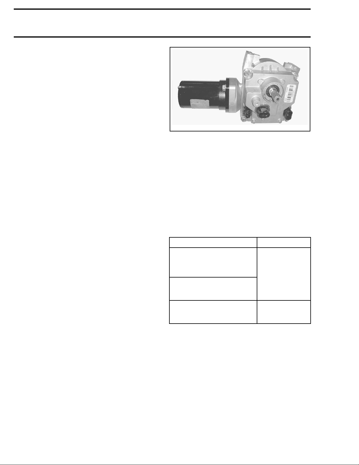
DPS SYSTEM DESCRIPTION
vmr2010-003-003
TYPICAL - DP
The DPS module provides DC power to the motor. The amount and duration of that DC power is
determined by the inputs to the DPS module. The
direction in which the motor turns is changed by
reversing the polarity of the circuit current.
The DPS mot
very small
ration, an
DPS module
DPS Unit Protection
To protect the DPS electronic components, the
steering assist behavior will change as follows.
When motor internal
temperature reaches a certain
temperature (DPS continuously
estimates it)
DPS internal board
temperature is above
85°C (185°F)
DPS internal board
temperature is above
100°C (212°F)
(COMPONENTS)
When the DPS unit temperature is back within
DPS Unit
The DPS unit is a self contained unit that includes
the steering gear, the DPS module, the DPS motor, and the torque sensor.
normal operating range, normal steering assist
will resume.
S UNIT
or does not "spin", but rather turns in
increments based on the amount, du-
d direction of DC power delivered by the
.
CONDITION DPS BEHAVIOR
Steering assist
will gradually
decrease
Steering assist
is stopped
512 vmr2015-142
Page 3
Section 07 CHASSIS
Subsection 03 (DYNAMIC POWER STEERING (DPS))
Steering Torque Sensor
rmr2008-019-017
The steer
the DPS un
magnetiz
surround
When the handlebar is turned, torque is applied to
the shaft which tends to twist the shaft slightly,
deforming the magnetic field in the shaft. The
sensor detects the torque by measuring the deviation of the magnetic field.
The torque sensor is very sensitive and can detect very small changes in the magnetic field.
The harder the handlebar is turned, the greater
the magnetic deviation, the greater the power
steering assist.
ing column is connected to the shaft on
it. A small area of the DPS shaft is
ed. Inside the DPS unit, a torque sensor
s the magnetized area of the DPS shaft.
PART ADJUSTED O
REPLACED
– DPS unit
– Steering colu
half bushings
– Steering col
–Tierod
–Tierodend
–Knuckle
– Wheel bearing
–Balljoint
– Front suspe
(lower/upper)
–Pitmanarm
– Steering alignment
1. Ensure pr
procedur
mn
umn
nsion arm
oper
e in this s ubsection.
R
WHAT TO DO
Reset Torque Offset
in Setting, D
PS
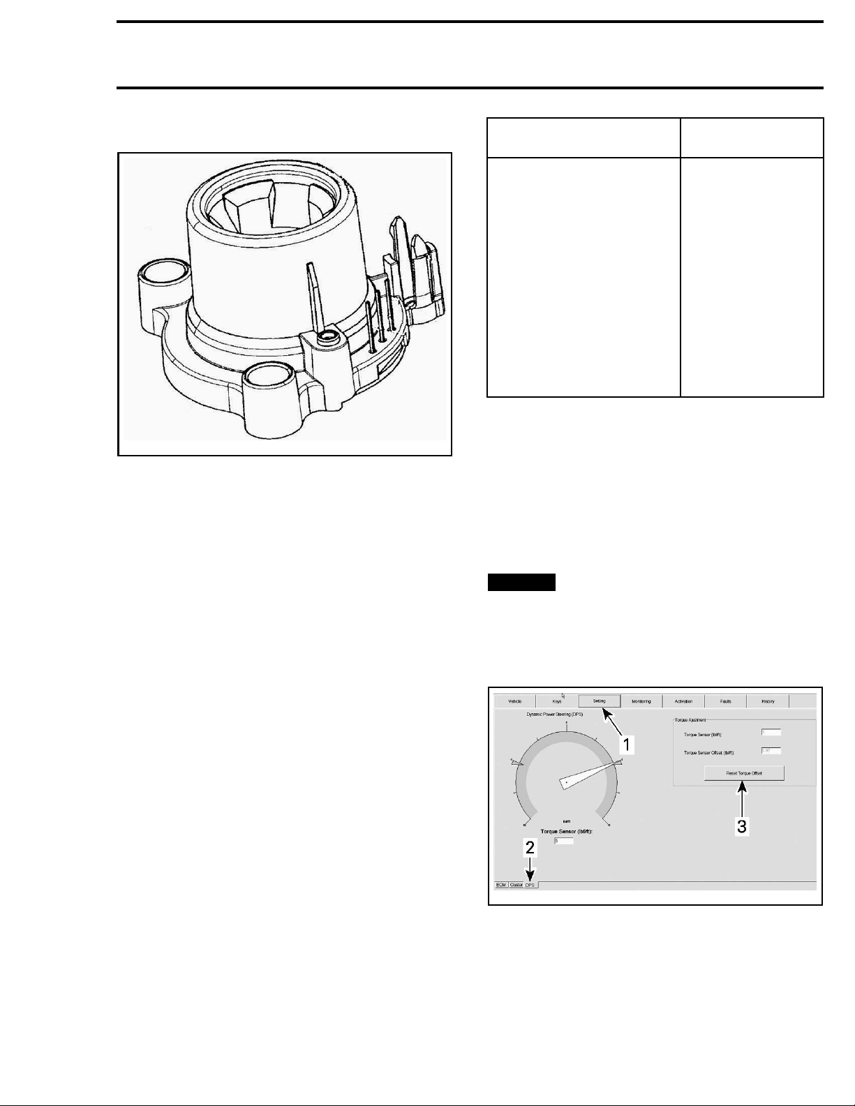
STEERING ALIGNMENT
,see
2. Connect vehicle to the latest applicable
B.U.D.S. software version.
3. In B.U.D.S., select Read Data.
4. Choose t
he Setting page tab.
5. At the bottom LH corner of the Setting page,
choose the DPS tab.
NOTICE
tered w
There M
ng column.
steeri
Ensure h
ithin ±10 degrees of center position.
UST NOT be any effort applied to the
andlebar is free and cen-
6. Press Reset Torque Offset button.
ADJUSTMENT
TORQUE OFFSET RESET
When re
steeri
be rese
vmr2015-142 513
placing the following parts or adjusting
ng alignment, the sensor torque offset must
t to zero) for proper system operation.
vmr2010-003-002_a
DPSTORQUEOFFSETRESET
1. Setting page tab
2. DPS tab
3. Reset Torque Offset button
Page 4
Section 07 CHASSIS
Subsection 03 (DYNAMIC POWER STEERING (DPS))
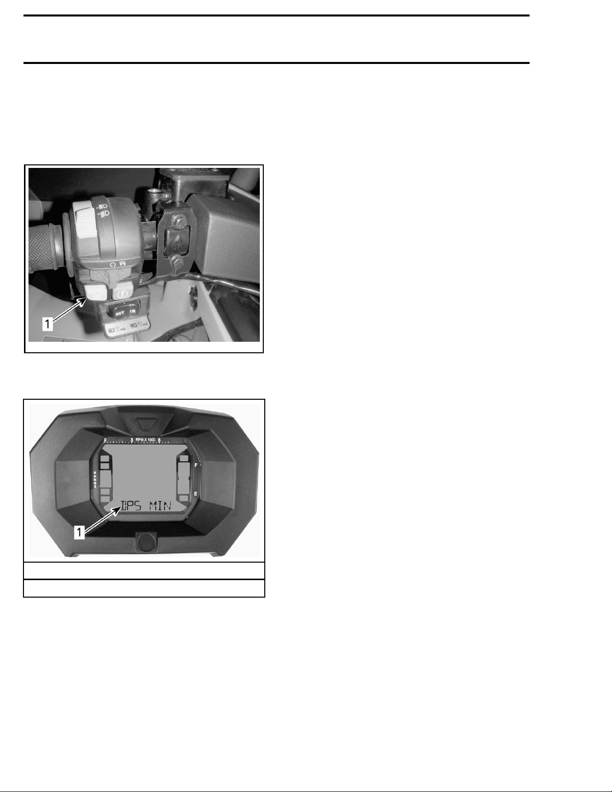
DPS ASSIST MODE
1. To view the active DPS ASSIST mode, momen-
tarily press and release the OVERRIDE/DPS
button on the LH multifunction switch assembly.
vmo2012-012-014_b
1. OVERRIDE/DPS/ACS button
The active DPS mode will be displayed in the
lower portion of multifunction gauge.
TROUBLESHOOTING
TROUBLESHOOTING FLOW
CHARTS
Use the troubleshooting flow charts to diagnose a
problem. If a problem cannot be solved, contact
a service representative for support before replacing a DPS.
Here is the lis
– Flow chart A: No Assistance From DPS
– Flow chart B: DPS Intermittent Assistance
–FlowchartC:
– Flow chart D: Free Play Felt in Steering System
– Flow chart E: Steering Turn Easier on One Side
than the Other.
t of provided flow charts:
Derating or Limited Assistance
LCD gauge
1. DPS mode indication
2. To change DPS ASSIST mode, press and hold
the OVERRIDE/DPS button for approximately 2
seconds to go to the next setting.
The DPS system will toggle to the following available mode. The newly activated DPS mode will
be briefly displayed in the multifunction gauge.
3. Repeat previous step to toggle through the
available mode.
NOTE: The DPS mode of operation cannot
be changed if the vehicle is in reverse. The
DPS/Override switch must be released between
each DPS mode selection.
514 vmr2015-142
Page 5
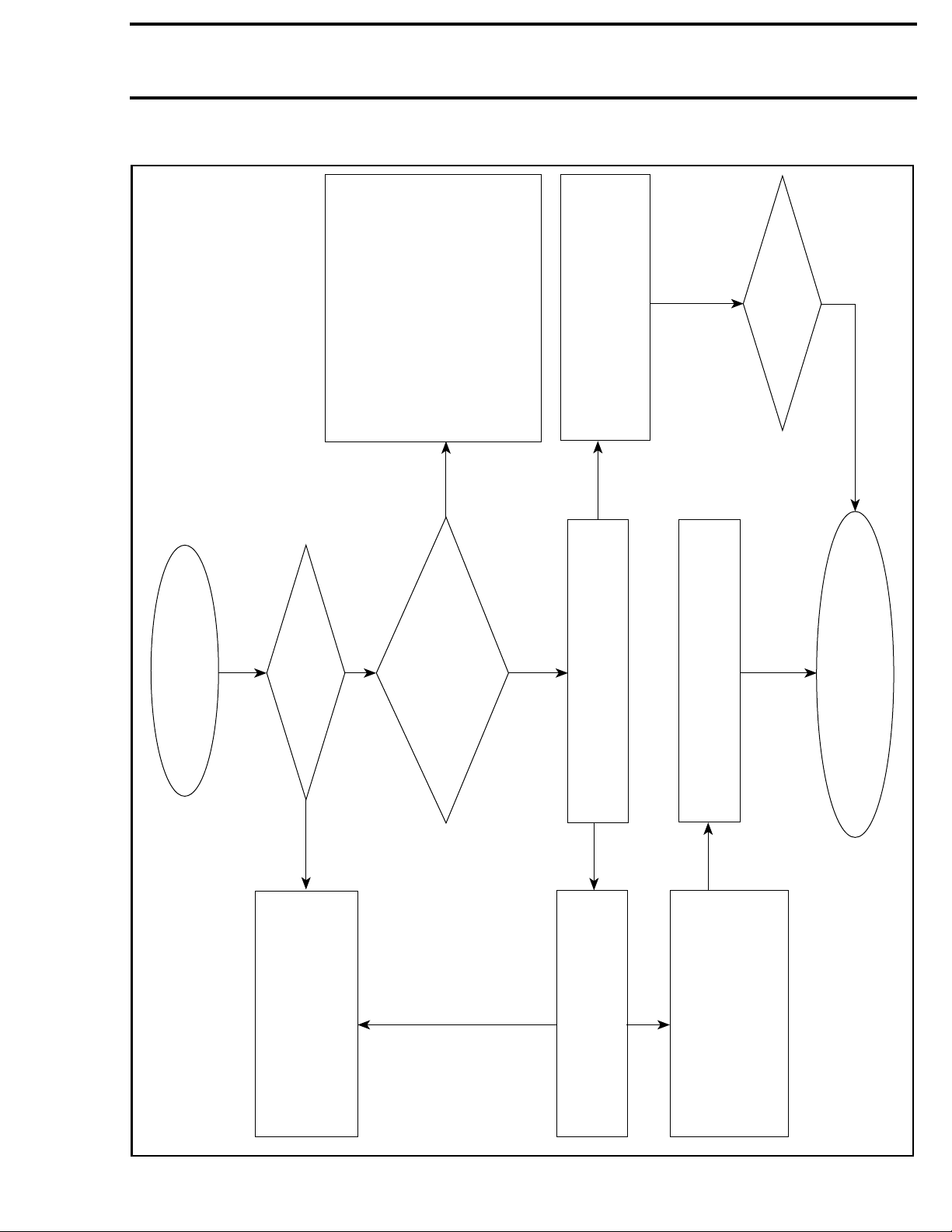
Flow Chart A
Subsection 03 (DYNAMIC POWER STEERING (DPS))
’ button to
• validate if DPS communicates with
• cluster.
• Check fuse F-3 (40A) - Check
••voltage at PWR connector
• Check battery voltage (min. 12V)
• Check DPS fuses F-4 (7.5A) - Push
• on ‘‘OVERRRIDE/DPS’
• and ground connections.
• Check ground going to DPS.
• Check all connector pins.
NOTE: Refer to appropriate Shop
Section 07 CHASSIS
invisible?
DPS tab still
• Check connection from ECM to DPS
unit.
• Check for proper B.U.D.S. version.
• Power down unit, reboot B.U.D.S.
Manual for proper validation.
then repower up.
NO
DPS?
Is it a replacement
No Assistance from DPS
YES
Is there voltage going
NO
to both wires of the DPS
connector)?
(power and control
NO
YES
ready to be sent.
If problem not solved:
and have the B.U.D.S. report
contact the Service Department
Consult B.U.D.S. screen for re-occurring
active or occured faults and perform
In B.U.D.S., click on Module (upper left in
screen), and validate if the DPS tab
is visible.
required service action.
Still no assistance?
YES
NO
Install latest calibration file
•
(FC file).
NOTE: New DPS comes without
calibration. Therefore, B.U.D.S.
must be used to install one.
vbs2014-009-001_aen
vmr2015-142 515
In B.U.D.S ., clic on Module,
DPS, Information and validate
if the Calibration Checksum
is VALID.
• Check if torque sensor values
• are varying in the B.U.D.S.
• monitoring screen while turn-
• ing the handlebars .
• Check if DPS motor is drawing
• amps in the B.U.D.S. monitoring
• screen (engine must be running).
Page 6
Section 07 CHASSIS
Subsection 03 (DYNAMIC POWER STEERING (DPS))
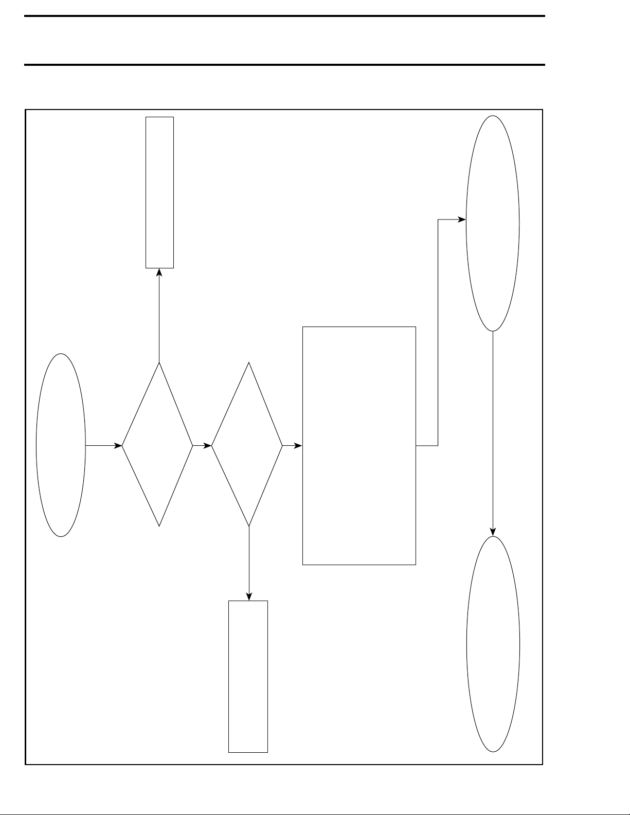
Flow Chart B
est again once pressure is
corrected.
• T
NO
Refer to
Flow Chart C.
Possibly related to derating.
DPS
Assistance
Intermittent
YES
Tire pressure good?
34 to 48 kPa (5 to 7 PSI)
screen?
Any active or
occured faults in B.U.D.S.
YES
NO
• Check battery voltage and ground connections.
• Check DPS fuses F-4 (7.5 Amp) & F-3 (40 Amp).
• Check power source and ground going to DPS.
• Check all connector pins.
• Check stator connector and charging system.
• Inspect all relevant wiring harnesses.
NOTE: Refer to appropriate Shop Manual for
proper validation.
If problem not solved,
and have the B.U.D.S. report
contact the Service Department
ready to be sent.
• Perform the required service
actions as per B.U.D.S. and/or
appropriate Shop Manual.
vbs2014-009-002_aen
516 vmr2015-142
Page 7
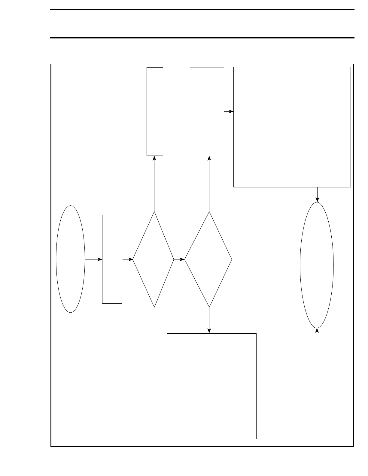
Flow Chart C
Section 07 CHASSIS
Subsection 03 (DYNAMIC POWER STEERING (DPS))
isco-Lok
Assistance
Derating or Limited
updates are proposed in
Make sure that no DPS file
• Inspect front brake pads for sticking.
Inspect drive shafts and V
•
functionnality.
If mechanical components are in good
condition, let the DPS unit cool down
before trying the vehicle again.
of the integrated protection system is
After the test, if the DPS unit works
properly, the problem is caused by the
activation of the integrated protection
If problem not solved:
file saved and ready to be sent.
normal.**
system. This situation is probably due to
severe riding conditions, the activation
est again once pressure is
corrected.
• T
NO
B.U.D.S.
Tire pressure good?
34 to 48 kPa (5 to 7 PSI)
• Verify steering components
for any interference or dam-
aged parts.
• Insure nothing limits the mov-
ement of steering components.
NO
bushings, tie-rod ends and ball joints
Inspect steering column, pitman arm,
for free normal movement (no obstructions).
•
YES
running?*
the engine is
Is there a voltage
drop a the battery when
the DPS is activated while
Contact service department if additional
YES
• Check battery voltage and ground
connections. If any doubt, install
a new fully charged battery.
• Verify charging system.
• Check stator connection.
• Check all connections related to
the DPS and charging system.
• Consult B.U.D.S. screen for
active or occured faults and
perform required service action.
NOTE: Refer to appropriate Shop
Manual for proper validation.
vbs2014-009-003_aen
vmr2015-142 517
information is required and have B.U.D.S.
*Refer to appropriate shop manual for procedure.
**Refer to derating explanation o n first page.
Page 8
Section 07 CHASSIS
Subsection 03 (DYNAMIC POWER STEERING (DPS))
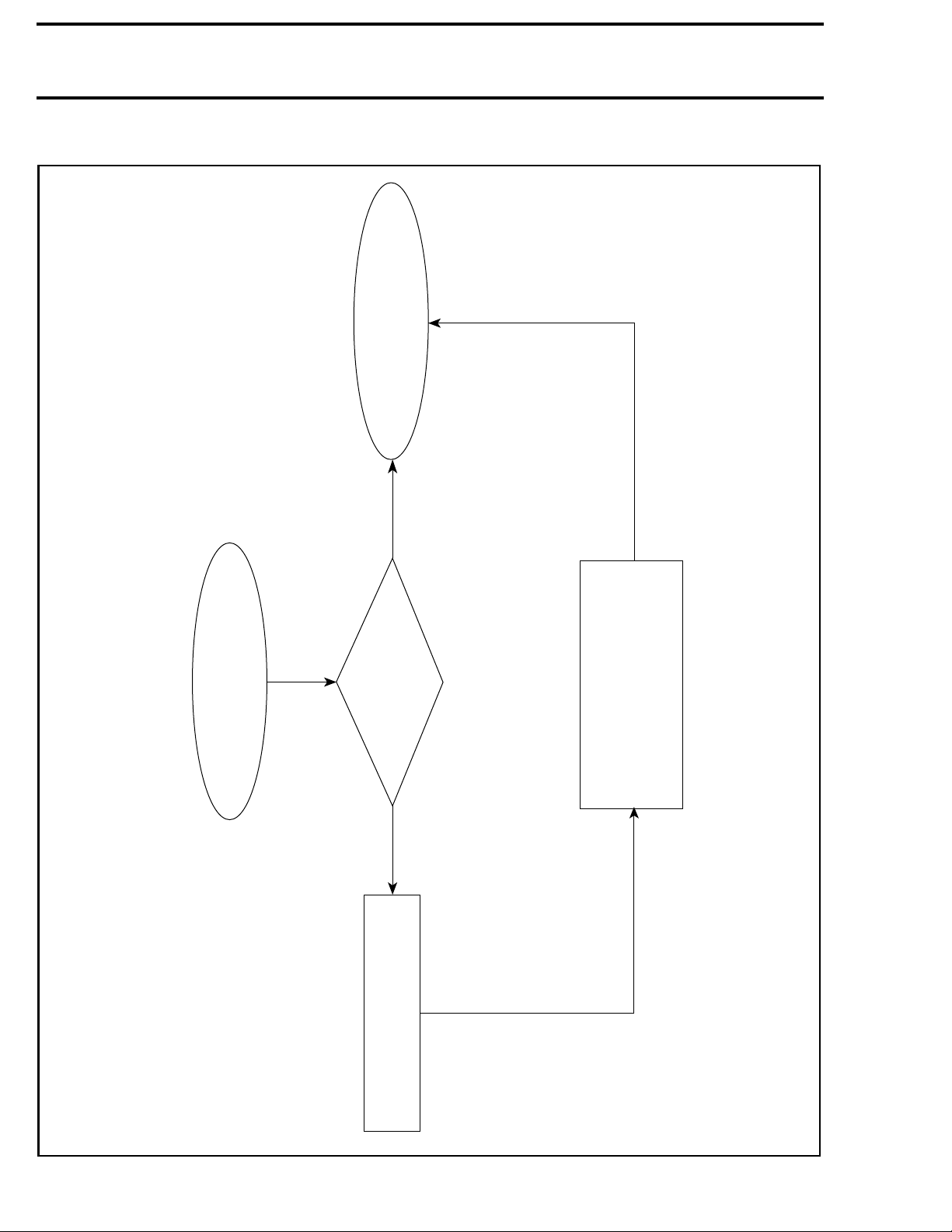
Flow Chart D
be sent.
Contact the service
B.U.D.S. report ready to
department and have the
still present
Free Play Felt in
Steering System
NO
Is there any
backlash or play in
YES
the steering system?
All OK and problem
• Verify that tie-rods, pitman arm,
ball joints, ,all steering
components and fasteners are
tight...........
• Ensure the upper steering
bushing is greased.
Bolt tight
bottom of the steering column
is tight.
• Verify if the pinch bolt at the
vbs2014-009-004_aen
518 vmr2015-142
Page 9
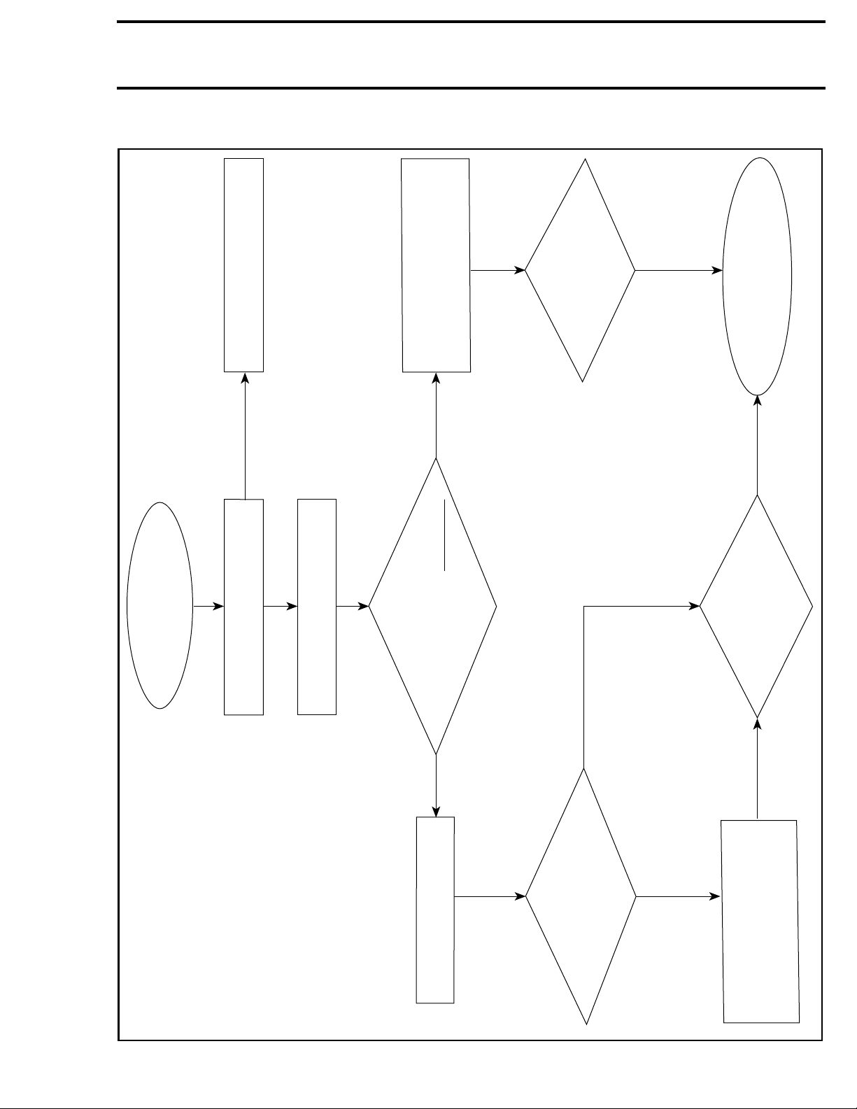
Flow Chart E
Section 07 CHASSIS
Subsection 03 (DYNAMIC POWER STEERING (DPS))
YES
• Test again once pressure and
alignment are corrected.
the Other Side
Steering Turns
Easier on One than
• Check tire pressure and
steering alignment.
• Connect to B.U.D.S. and go to
the DPS monitoring screen.
• Check for faults and perform
required actions.
• Ensure the latest calibration file
is installed.
NO
ahead?
Is torque offset value
and are positioned straight
more than 3 N•m when the
handlebars are free, untouched
faults or
symptoms?
Re-occurring
NO
be sent.
Contact the service
B.U.D.S. report ready to
department and have the
YES
exist?
issues still
Any of the previous
YES
YES
torque sensor fault?
Can’t reset the torque
sensor or a re-occurring
• Re-set the torque sensor.
• Make sure nothing touches
the steering column.
• Verify steering column align-
ment as per appropriate Shop
Manual.
vbs2014-009-006_aen
vmr2015-142 519
Page 10
Section 07 CHASSIS
Subsection 03 (DYNAMIC POWER STEERING (DPS))
PROCEDURES
DPS UNIT
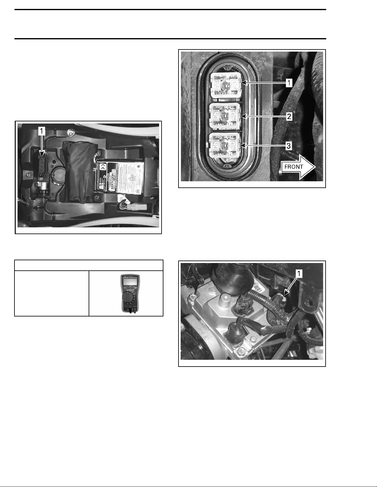
DPS Unit Fuse T
est
A 40 A DPS fuse located in a fuse holder, on the
RH side of the frame, under the battery support,
provides power for the DPS motor.
vmr2012-023-003_d
TYPICAL
1. Rear fuse box (PF2)
1. Test DPS fuse (PF2-F3) using a multimeter.
vmr2012-029-002_a
TYPICAL
1. 30 A Main
2. 40 A Fan/accessories
3. 40 amp DPS fuse
2. Replace fuse as required.
DPS Unit Input Voltage Test (Power
Side)
1. Disconnect the DPS PWR (power) connector.
REQUIRED TOOL
FLUKE 115
MULTIMETER
(P/N 529 035 868)
vmr2010-003-013_d
TYPICAL
1. DPS PW
R connector (motor power)
2. Test for 12 Vdc DPS motor power at DPS2-A
and DPS2-B as per following table.
520 vmr2015-142
Page 11
Section 07 CHASSIS
Subsection 03 (DYNAMIC POWER STEERING (DPS))
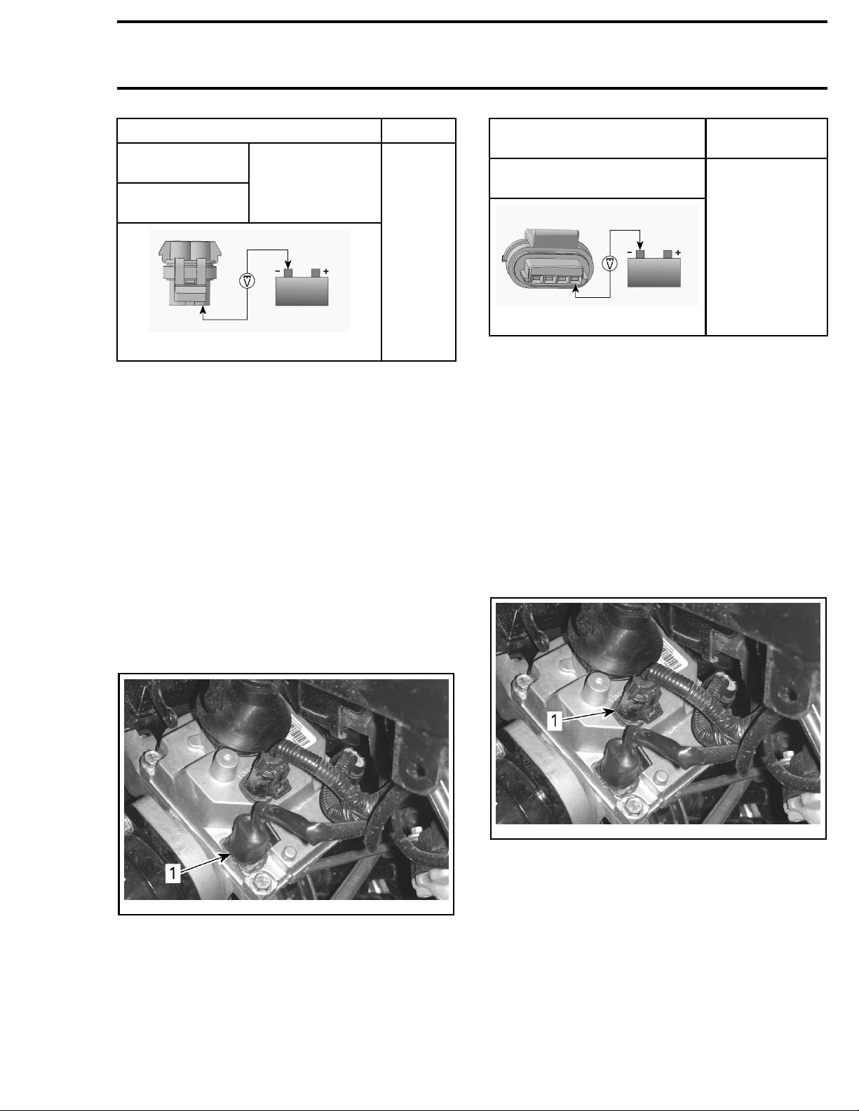
MULTIMETER PRO
DPS2 power
connector pin A
DPS2 power
connector pin
rmr2008-028-091_a
BE POSITIONS
Battery ground
B
VOLTAGE
Battery
voltage
If NO voltage is measured, test the 40 A DPS fuse
in the rear fuse holder (PF2-F3). If good, check
wires and connector pins. Replace or repair defective parts and reset fault codes.
If battery voltage is measured, carry out the following
TROL SIDE)
NOTE: This
necting a 1
PWR connec
negative t
DPS UNIT INPUT VOLTAGE TEST (CON-
.
test may also be carried out by con-
2 Vdc test light between each DPS
tor pins (A and B), and the battery (-)
erminal. The test light must come on
bright.
MULTIMETER PRO
POSITIONS
DPS control con
and battery ground
rmr2008-028-093_a
nector (pin A)
BE
VOLTAGE
Battery voltage
If NO voltage is measured, check wires and connector pins from DPS unit to the Relays/Speedo
fuse in front fuse box (PF1-F4). Replace or repair
defective parts and reset fault codes.
If battery voltage is measured, carry out the following
DPS UNIT GROUND CIRCUIT TEST
NOTE: This
necting a 1
trol conne
terminal.
ctor (pin A), and the battery (-) negative
The test light must come on bright.
test may also be carried out by con-
2 Vdc test light between the DPS con-
.
DPS Unit Ground Circuit Test
1. Disconnec
t the DPS ground connector (GDN).
DPS Unit Input Voltage Test (Control
Side)
1. Disconnect DPS CTRL (control) connector.
vmr2010-003-013_b
AL
TYPIC
1. DPS CTRL (control) connector
2. Set the ignition switch to ON.
3. Set the engine RUN/STOP switch to RUN.
4. Test
for 12 Vdc power to the DPS module at
-A as per following table.
DPS1
vmr2010-003-013_c
TYPICAL
1. DPS ground connector (GDN)
2. Test for continuity between DPS3-A and
DPS3-B to battery ground.
vmr2015-142 521
Page 12
Section 07 CHASSIS
Subsection 03 (DYNAMIC POWER STEERING (DPS))
MULTIMETER PRO
POSITIONS
DPS GDN
connector pin A
Battery ground
DPS GDN
connector pin B
BE
READING
Continuity
(close to 0
)
If there is NO continuity or a high resistance is
measured, check wires and connector pins from
DPS unit to chassis ground post. Replace or repair defective parts and reset fault codes.
If there is good continuity, carry out the following
DPS UNIT COMMUNICATION LINK (CAN) CONTINUITY TEST
NOTE: This te
necting a 12
connector p
nal. The tes
.
st may also be carried out by con-
Vdc test light between each GDN
in and the battery (+) positive termit light must come on bright.
DPS Unit Communication Link (CAN)
Continuity
NOTE: DPS unit must receive an RPM signal to
provide power steering assist.
1. Disconnect the DPS control connector and the
diagnostic connector.
2. Test conti
and DPS1-D
Tes t
nuityofCANBusWiresatDPS1-C
.
If resistance measured is out of specification,
check wires and connector pins. Carry out repairs as required and reset fault codes using
B.U.D.S software.
If resistance measured is good, replace the DPS
unit and reset fault codes using B.U.D.S software.
DPS System Load Test
If the charging system cannot sustain normal v oltage when the DPS is operating, DPS ASSIST may
be greatly reduced or nonexistent. Carry out the
following steps.
1. Measure the battery voltage.
NOTE: If battery voltage is low, recharge battery.
2. Ensure the vehicle transmission is set to PARK.
3. Start the engine.
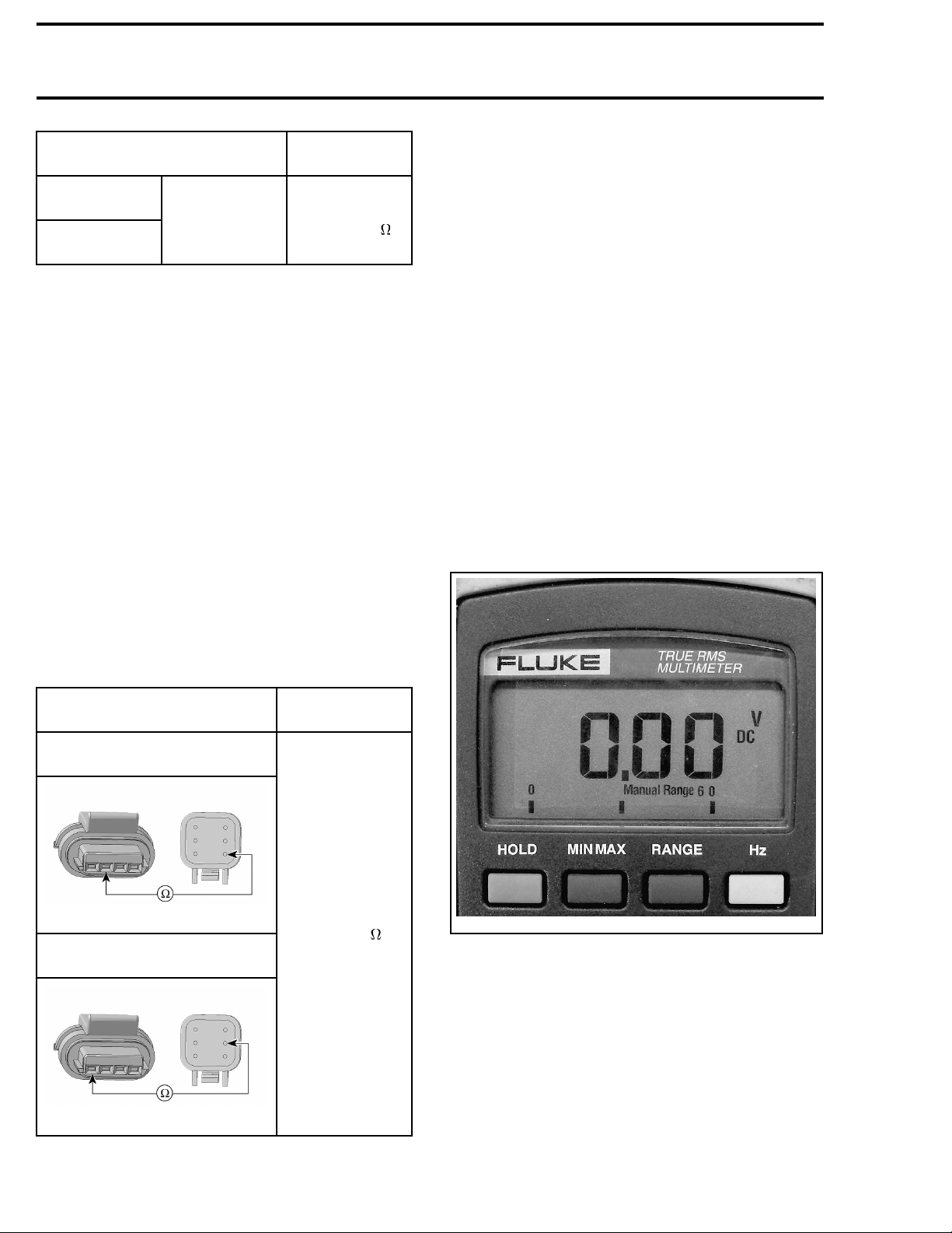
4. Note the voltage on the multimeter with the engine running (charging system voltage).
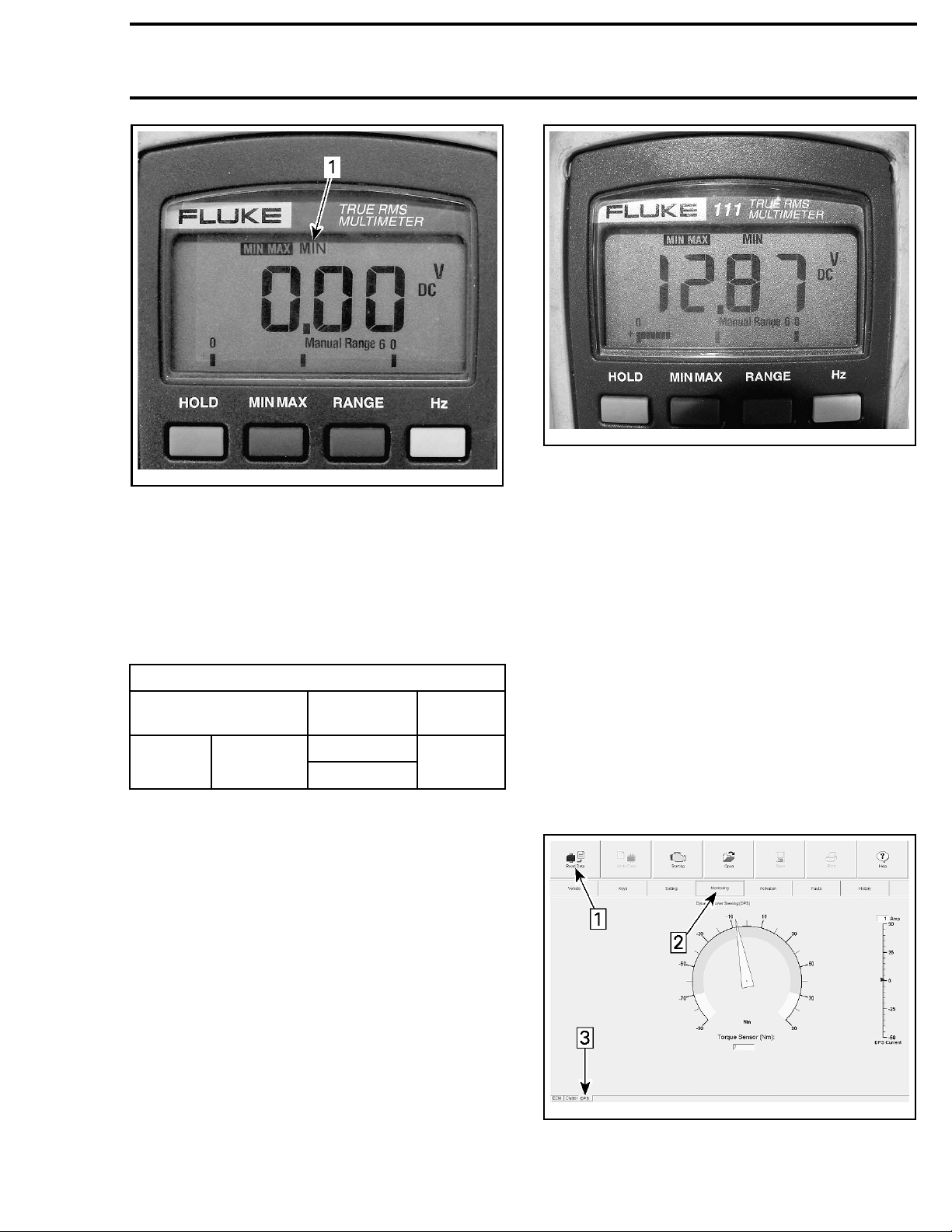
5. Press the RANGE button repeatedly to select
Manual Range 6 0.
MULTIMETER PROBE
POSITIONS
DPS control connector (pin C)
and diagnostic connector (pin 1)
rmr2008-028-094_a
DPS control connector (pin D)
and diag
rmr2008-028-094_b
nostic connector (pin 2)
RESISTANCE @
20°C (68°F)
Below 1
mmr2009-023-027_a
VDC SELECTED TO MANUAL RANGE 6 0
6. Press the MIN MAX button on the multimeter
to engage the MIN function.
522 vmr2015-142
Page 13
Section 07 CHASSIS
Subsection 03 (DYNAMIC POWER STEERING (DPS))
vmr2010-003-007
mmr2009-023-027_e
1. MIN function selected
7. Turn the handlebar momentarily against the
steering frame stops to each side.
NOTE: Do not hold steering against frame stops
for an extended period of time.
8. Read the MIN charging system voltage
recorded while the handlebar was turned
against each s top.
DPS SYST
PROBE POSITIONS
Battery (-)
terminal
DPS fuse
holder pin B
EM LOAD TEST
STEERING
POSITION
LH stop
RH stop
VOLTAGE
READING
At least
12 Vdc
NOTE: Turning the handlebar momentarily
against the frame stops generates maximum
DPS load (maximum current draw on electrical
system). Electrical system must sustain at least
12 Vdc for proper DPS operation.
If the elec
12 Vdc, che
trical system cannot sustain at least
ck the following:
– Battery
– Battery connections
– DPS unit p
ower and ground connections
– Charging s ystem
– Frame and engine ground studs.
If the previously listed items, carry out the following
DPS UNIT CURRENT TEST
.
DPS Unit Current Test
1. Connect vehicle to the latest applicable
B.U.D.S. software version.
2. Click on
3. Choose the Monitoring page tab.
4. At the bottom of the Monitoring page, choose
the DPS tab.
the Read Data button.
vmr2010-003-008_a
Step 1: Press Data button
Step 2: Select Monitoring page tab
Step 3: Select DPS tab
vmr2015-142 523
Page 14
Section 07 CHASSIS
Subsection 03 (DYNAMIC POWER STEERING (DPS))
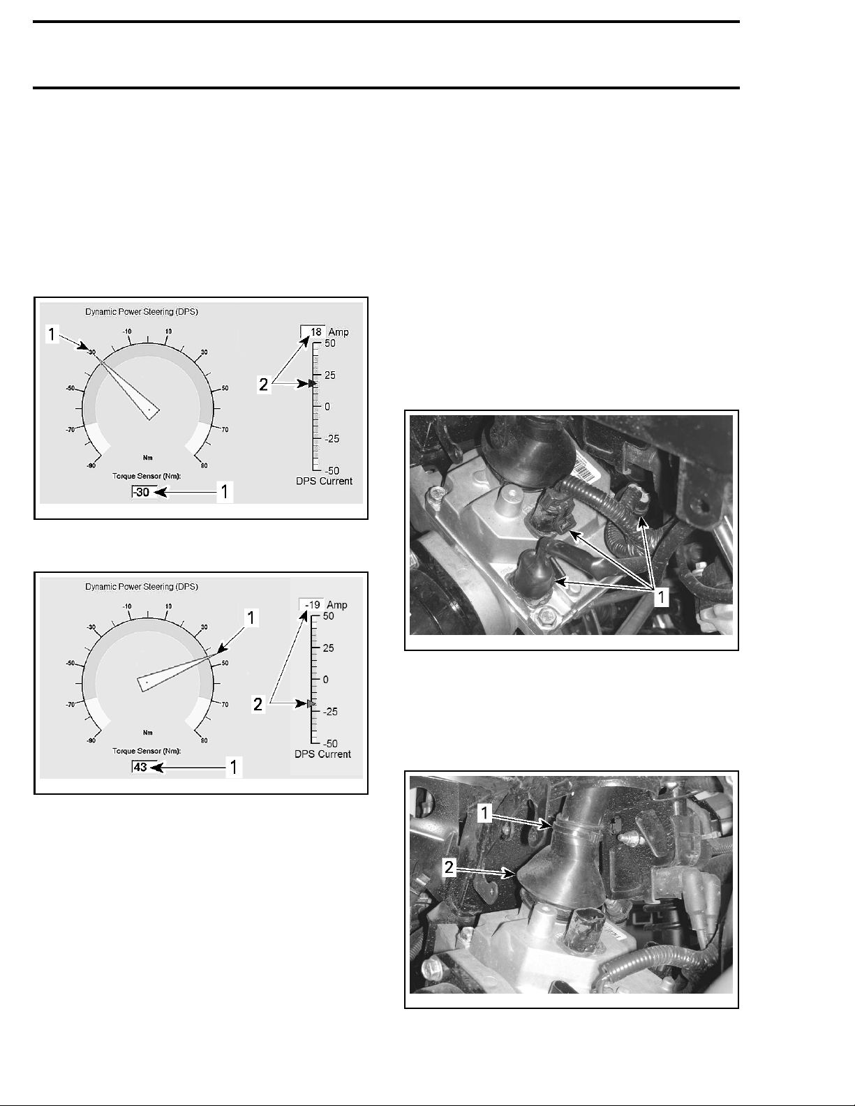
5. With the vehicle engine running in PARK, turn
the handlebar side to side, momentarily against
each stop and observe the indications on the
B.U.D.S. DPS Monitoring page.
The DPS Torque Sensor Nm increase with torque
applied to handlebar.
The DPS Current ammeter should increase proportionately to the torque applied, and decrease
with the torque as steering assist is provided.
003-009_a
vmr2010-
TYPICAL - LH TURN
1. Torque sensor indication (negative)
2. DPS curre
nt indication (positive)
– Steering column shim adjustment at half bush-
ings as described in the
procedure detailed in this section.
TION
TORQUE OFFSET RESET
–
DPS UNIT INSTALLA-
procedure detailed in
this section.
– Replace DPS unit.
DPS Unit Removal
1. Remove the front body module, refer to
subsection.
2. Remove both inner fender panels
3. Remove the CVT air inlet duct assembly, refer
AIR INTAKE SYSTEM
to
subsection.
4. Disconnect the 3 electrical connectors from the
DPS unit.
BODY
vmr2010-003-010_a
TYPICAL - RH TURN
1. Torqu
2. DPS current indication (negative)
e sensor indication (positive)
NOTE: Increase and decrease in torque and current readings is very brief as steering assist is
quickly provided. Current draw should remain
within green scale but may momentarily peak to
60 amps, then drop off close to 0 amps as torque
applied is nulled out by steering assist. A residual
torque of 2 N•m (18 lbf•in) with a corresponding
current draw is acceptable.
If current draw tends to remain high, carry out the
following:
– Steering alignment check.
-003-013_a
vmr2010
TYPICAL
1. DPS connectors (3x)
5. Cut the
bottom
and pul
cess th
vmr2010-003-016_a
TYPICAL
1. Cut this locking tie
2. Steering column bellows
locking tie securing the bellows at the
of steering column near the DPS unit,
l the bellows upwards sufficiently to ace steering column pinch bolt.
524
vmr2015-142
Page 15
Subsection 03 (DYNAMIC POWER STEERING (DPS))
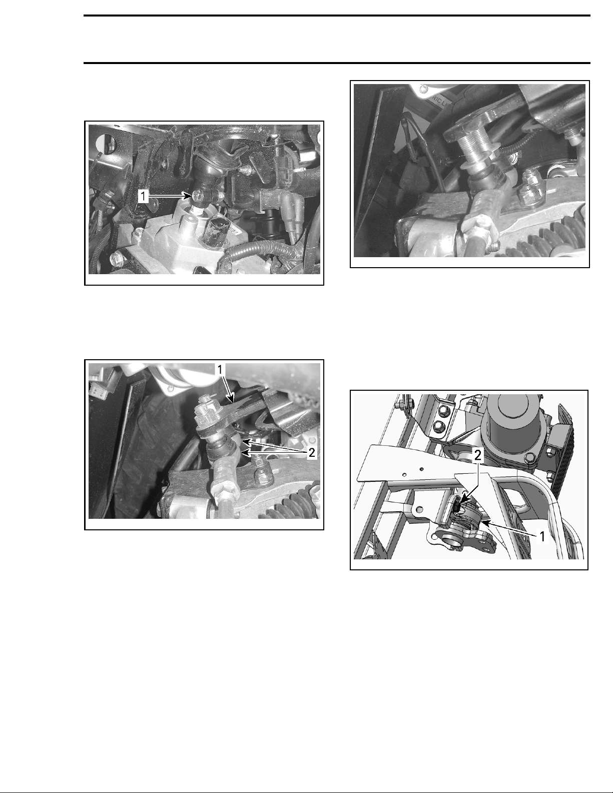
6. Remove the steering column pinch bolt and retaining nut. Discard the retaining nut.
03-017_a
vmr2010-0
TYPICAL
1. Steering column pinch bolt
7. Remove the
ends to th
cotter pi
hardware that secures both tie-rod
e pitman arm (steering lever). Discard
ns.
Section 07 CHASSIS
vmr2010-003-023
TYPICAL - TIE ROD ENDS (HARDWARE REMOVED)
9. Pull up on the steering column to partly disengage it from the DPS unit.
NOTE: A mechanical stop on the steering column
will prevent you from fully disengaging the steering column.
10. Remove th
secures t
e lower half bushing retainer that
he steering shaft to the frame.
vmr2010-003-022_a
TYPICAL
1. Pitman arm
2. Tie rod ends
8. Turn the steering to each side and disengage
each tie-rod end from the pitman arm.
vmr2012-039-013_a
1. Lower half bushing retainer
2. Bolts to remove (2)
11. Remove the 2 hexagonal flanged screws securing the DPS unit to the RH support bracket.
vmr2015-142 525
Page 16
Section 07 CHASSIS
Subsection 03 (DYNAMIC POWER STEERING (DPS))
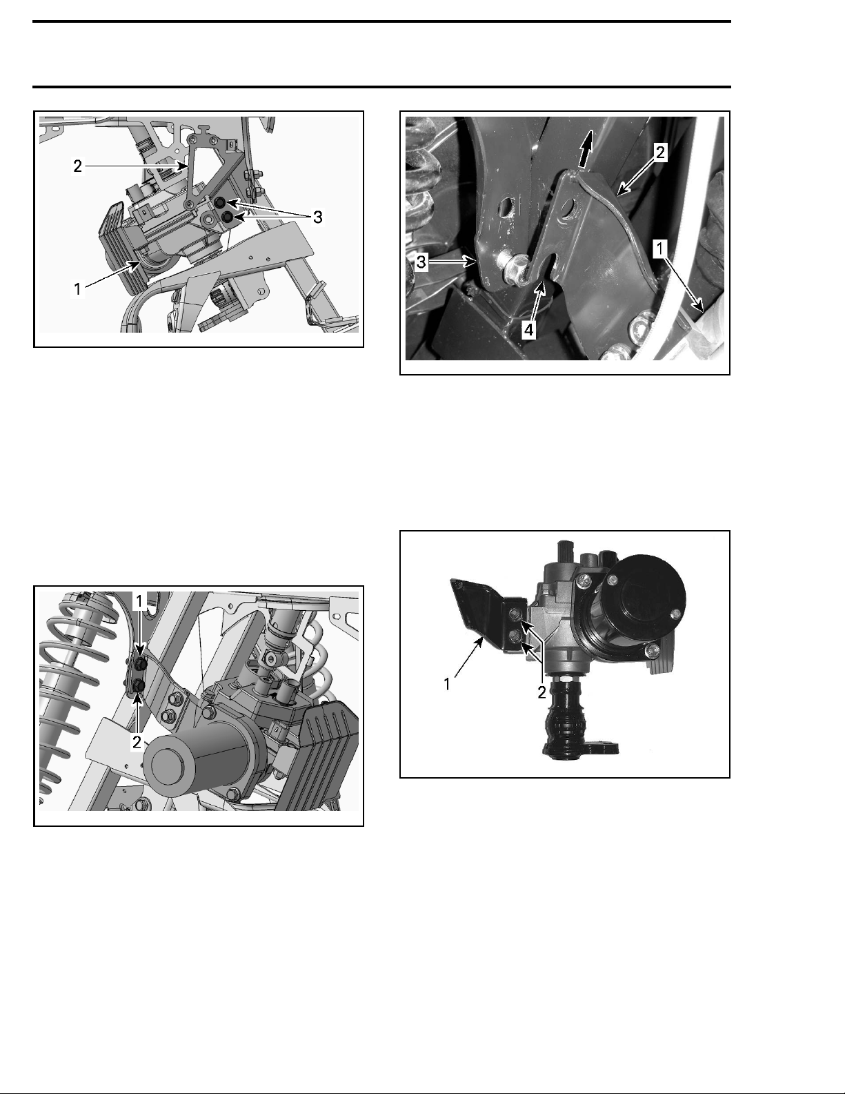
vmr2012-039-014_a
DPS REMOVAL - RH SIDE
1. DPS
2. RH DPS support bracket
3. Remove these screws (2)
NOTE: Discard the conical spring washers on the
DPS retaining screws.
12. On the LH side of the DPS unit, remove the
DPS support bracket from the frame in the following manner:
12.1 Remove the top retaining screw.
12.2 Loosen the lower retaining screw suffi-
ciently for the bracket to become loose
on the frame.
vmr2012-039-016_a
TYPICAL - LH DPS SUPPORT BRACKET
1. DPS unit
2. DPS support bracket
3. Vehicle frame
4. Slotted hole in DPS support bracket
14. If replacing DPS unit, remove the following
from the DPS unit:
– LH DPS support bracket
– DPS heat shield.
vmr2012-039-034_a
support bracket
12-039-015_a
vmr20
DPS REMOVAL - LEFT SIDE
Step 1: Remove DPS retaining screws (2 each side)
: Discard conical washers under screw head
Step 2
1. LH DPS
2. Retaining screws
NOTE: When removing the DPS heat shield, hold
the DPS housing screws steady using a wrench
to as you remove the 2 heat shield retaining nuts.
13. Pull up on DPS unit to remove the DPS unit
and support bracket from the frame.
526 vmr2015-142
Page 17
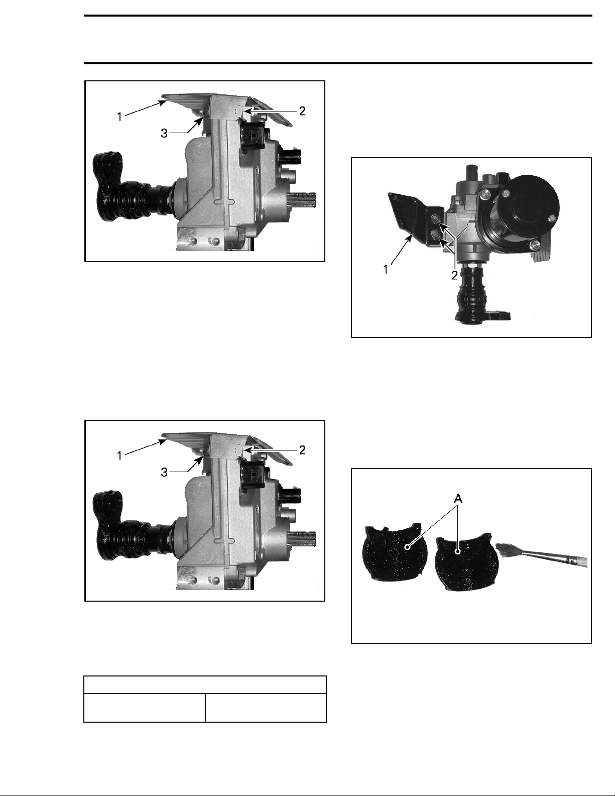
Subsection 03 (DYNAMIC POWER STEERING (DPS))
vmr2012-039-035_a
1. DPS heat shield
2. Retaining screws to hold steady (2 not visible)
3. Retaining nuts to remove
DPS Unit Installation
IMPORTANT: The following hardware must all
be replaced with new ones:
– Hexagonal forming screws with threadlocker
– Conical spring washers
– Elastic nuts.
1. If the DPS unit is being replaced, install heat
shield from old DPS unit onto new DPS unit.
Section 07 CHASSIS
NOTE: Important: Install the retaining screws to
the DPS support bracket loosely at this time. This
is required to ensure proper DPS alignment at a
later step when all steering and DPS fasteners are
tightened to specified torque.
039-034_a
vmr2012-
1. LH DPS support bracket
2. Retaining screws
3. Ensure "
conditi
4. Apply
to:
– The ins
ings
– The steering shaft and "O" rings.
O" rings on steering shaft are in good
on.
XPS SYNTHETIC GREASE (P/N 293 550 010)
ide of both steering shaft half bush-
12-039-035_a
vmr20
1. DPS heat shield
2. Retaining screws to hold steady (2 not visible)
3. Retai
NOTE: Important: Hold DPS housing screws
steady using a wrench as you apply specified
ning nuts to rem o v e (2)
vmr2012-039-017_a
A. XPS synthetic grease (P/N 293 550 010) here
torque to heat shield retaining nuts.
TIGHTENING TORQUE
Retaining nuts, DPS
heat shield
24.5 N•m ± 3.5 N•m
(18lbf•ft ±3lbf•ft)
2. Install LH DPS support bracket loosely using
NEW fasteners.
vmr2015-142 527
Page 18
Section 07 CHASSIS
Subsection 03 (DYNAMIC POWER STEERING (DPS))
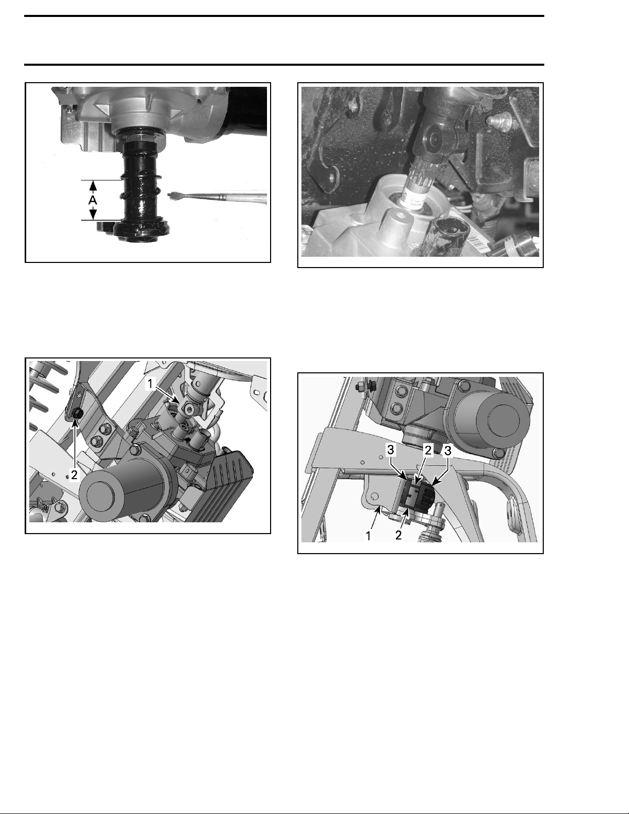
vmr2012-039-018_a
A. XPS synthetic grease (P/N 293 550 010) here
5. Insert the steering c olumn onto the DPS input
shaft
6. Position the LH DPS support bracket onto the
hexagonal forming screw that was left on the
frame DPS mount.
vmr2012-039-019_a
1. Steering column onto the DPS input shaft here
2. LH DPS
support bracket onto the hexagonal forming screw here
NOTE: The DPS shaft splines have a key which
must be aligned with the keyway in the steering
column.
vmr2010-003-031
TYPICAL - STEERING COLUMN INDEXED TO DPS SHAFT
SPLINES
7. Ensure the following are properly positioned
on the lower steering shaft and lower steering
shaft mount.
– O-rings
– Steering
vmr2012-039-020_a
1. Lower steering shaft mount
2. O-rings
3. Steering shaft half bushings
shaft half bushings.
8. Install the 3 remaining hexagonal forming
screws that secure the DPS unit loosely using
NEW fasteners.
NOTE: Ensure the support bracket retaining
screws have a NEW conical spring washer between the screw head and the DPS frame support.
Ensure both tie rod ends have a hardened steel
washer on them, then insert the tie-rod ends onto
thepitmanarm.
528 vmr2015-142
Page 19
Section 07 CHASSIS
Subsection 03 (DYNAMIC POWER STEERING (DPS))
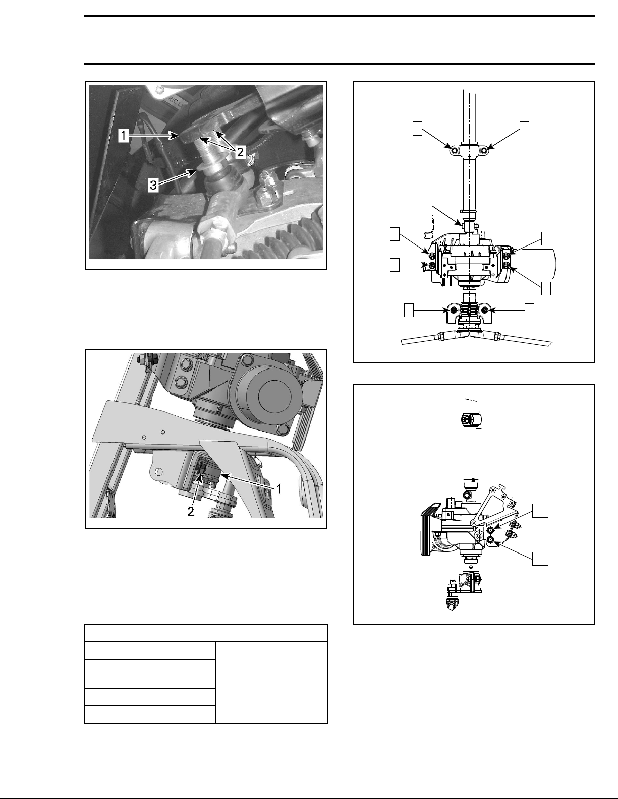
vmr2010-003-023_a
TYPICAL
1. Pitman arm
2. Tie rod ends inserted in pitman arm
3. Hardened steel washer on tie rod end
9. Install the lower half bushing retainer loosely
using NEW fasteners.
4
5
1
6
8
2
vmr2012-039-100_a
DPS AND STEERING TORQUE SEQUENCE (1 OF 3)
3
7
9
10
vmr2012-039-021_a
1. Lower half bushing retainer
2. Hexag
10. Install steering column pinch bolt and a NEW
11. Tigh
vmr2015-142 529
onal forming screws installed loosely
elastic nut loosely.
ten the steering and DPS fasteners to
ified torque using the torque sequence
spec
ified in the following 3 illustrations.
spec
TIGHTENING TORQUE
DPS retaining screws
DPS bracket retaining
screws
Steering column retainer
Steering column pinch bolt
12
vmr2012-039-101_a
DPS AND STEERING TORQUE SEQUENCE (2 OF 3)
24.5 N•m ± 3.5 N•m
(18lbf•ft ± 3lbf•ft)
Page 20
Section 07 CHASSIS
Subsection 03 (DYNAMIC POWER STEERING (DPS))
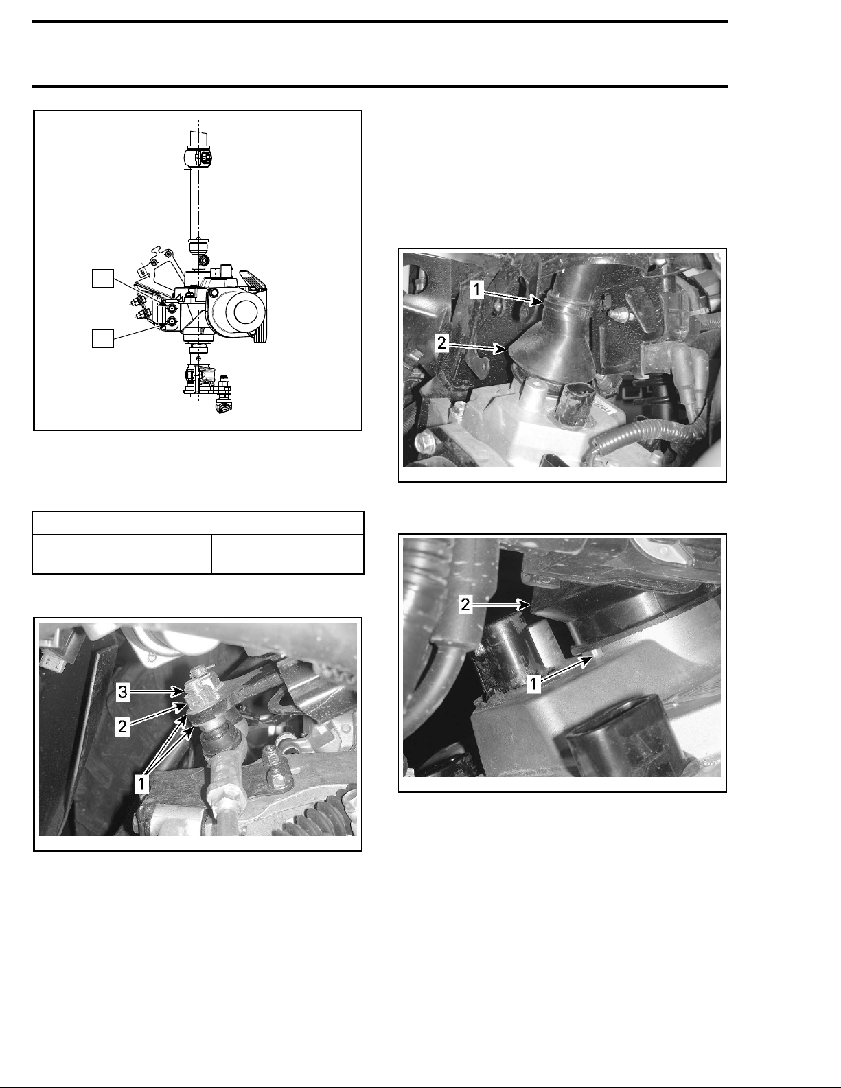
NOTE: Ensure the locking tie is on the tube part of
the steering column, not on the forged end. Bellows should cover end of ring flange on DPS unit
but not cover the drainage hole at the bottom of
the ring flange. Do not install a locking tie on the
DPS end of the bellows. Lower portion of bellows
MUST remain floating over the DPS housing.
11
13
vmr2012-039-102_a
DPS AND STEERING TORQUE SEQUENCE (3 OF 3)
12. Install the second hardened steel washer and
nut on each tie-rod end. Tighten retaining nuts
as specified.
TIGHTENING TORQUE
Tie-rod end to pitman arm
72.5 N•m
(53lbf•ft ± 6lbf•ft)
±7.5N•m
13. Install NEW cotter pins on the tie-rod ends.
vmr2010-003-022_b
TYPICAL
1. Hardened steel washers (one each side of pitm an arm)
2. Tie rod end retaining nut (torque applied)
3. NEW cotter pin installed
003-016_a
vmr2010-
TYPICAL
1. Locking tie location
2. Steering
vmr2010-003-033_a
TYPIC
1. Drainage hole in DPS ring flange
2. Steering column bellows
15. Turn
column bellows
AL
handlebar fully to each side and check for
er contact between pitman arm and pit-
prop
man a
rm frame stops (both sides).
14. Pull bellows down over steering column pinch
bolt and edge of DPS unit housing extension.
Secure bellows using the appropriate locking
tie.
530 vmr2015-142
Page 21
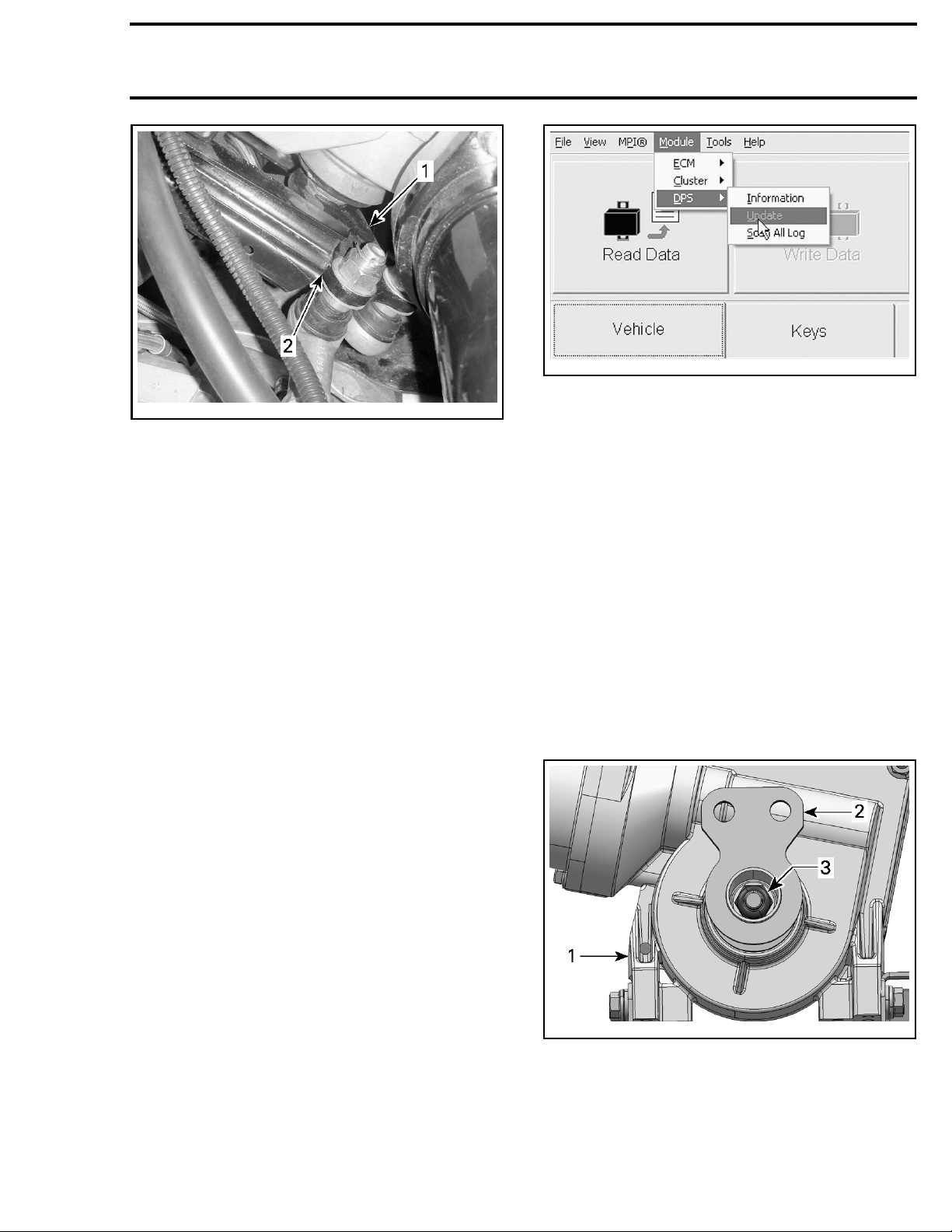
Subsection 03 (DYNAMIC POWER STEERING (DPS))
vmr2010-003-039_a
TYPICAL - LH ILLUSTRATED
1. Pitman arm
2. Contact point with frame stop
NOTE: Contact between pitman arm and pitman
arm stops must be checked with vehicle weight
on wheels.
16. Reconnect DPS electrical connectors.
17. P erform a
STEERING ALIGNMENT
scribed in the applicable Shop Manual subsection.
18. If installing a replacement DPS unit, refer to
DPS REPLACEMENT
in this subsection.
19. Perform the torque offset reset. Refer to
TORQUE OFFSET RESET
in this subsection.
20. Install all other removed parts in the reverse
order of removal.
21. Carry out a test ride of the ATV to ensure
proper operation of the DPS unit.
as de-
Section 07 CHASSIS
vmr2010-003-040
DPS SOFTWAR
EUPDATE
4. Once the correct DPS software file is installed,
go to the Faults page and clear the fault codes.
5. Carry out t
dure as des
TORQUE OFFSET RESET
cribed in this subsection.
proce-
he
6. Test drive the ATV to ensure proper DPS operation.
PITMAN ARM
NOTE: On models without a DPS, the pitman
arm is replaced with the steering column. Refer
to STEERING COLUMN in this subsection.
Pitman Arm Removal
1. Remove DPS unit from vehicle, refer to
REMOVAL
2. Remove P
in this subsection.
itman arm retaining nut and washer.
DPS
DPS Unit Replacement
New DPS units do not come with the required
software programmed into the unit. A DPS unit
fault will be generated when the vehicle is powered up. The check engine light will come on and
a DPS FAULT message will appear in the multifunction gauge.
When DPS unit installation is complete, carry out
the following steps.
1. Connect the ATV to the latest applicable
B.U.D.S. software version.
2. Select the Read Data button.
3. In the Module menu, choose the DPS submenu and install the latest DPS software
Update file as applicable to the type ATV (Outlander or Renegade).
vmr2015-142 531
vmr2012-039-022_a
1. DPS
2. Pitman arm
3. Pitman arm nut and washer
3. Install the pitman arm jig in a vise with the positioning screw upward.
Page 22
Section 07 CHASSIS
Subsection 03 (DYNAMIC POWER STEERING (DPS))
REQUIRED TOOLS
PITMAN ARM JIG
(P/N 529 036 22
5)
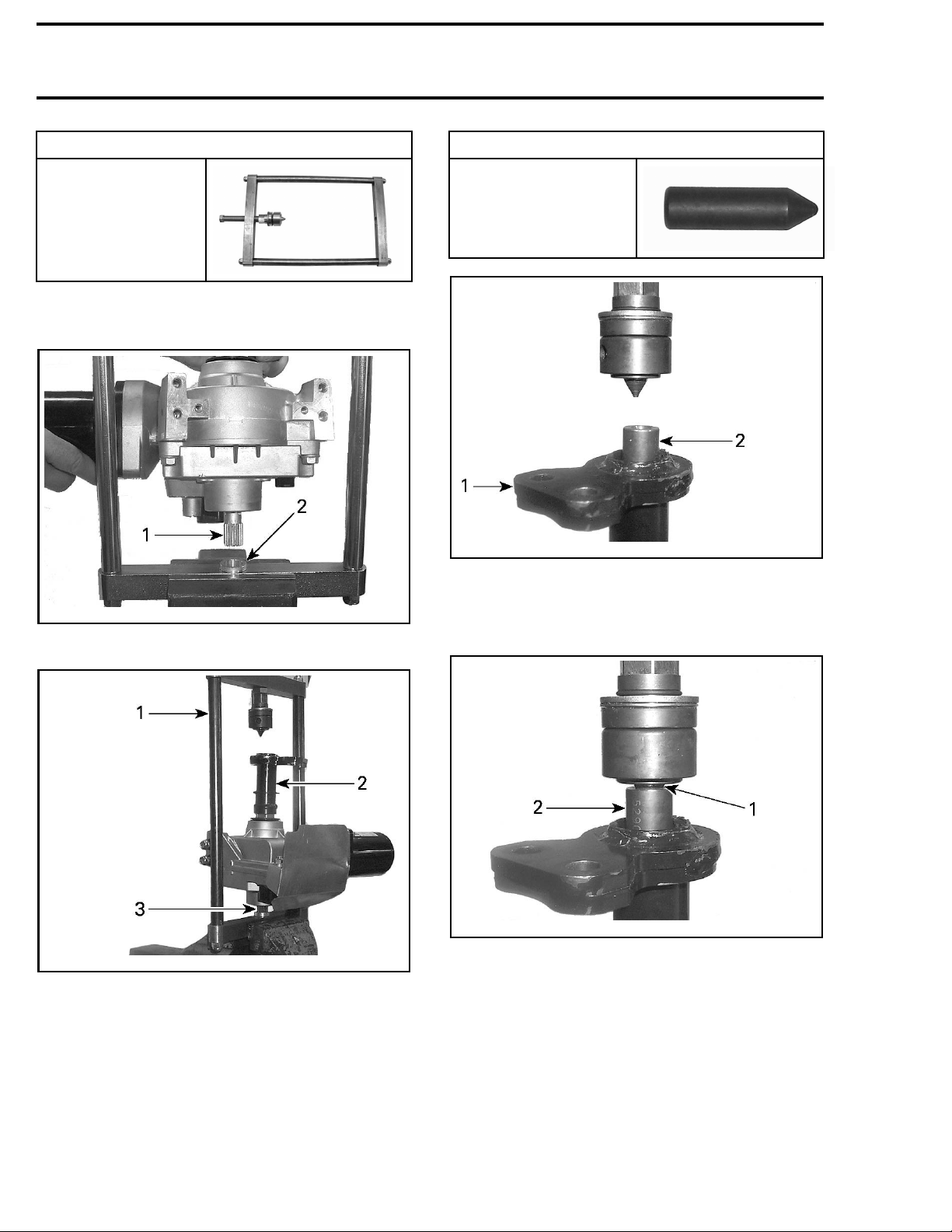
4. Insert the DPS input shaft in the Pitman arm jig
receptacle with the Pitman arm facing up.
POSITIONING
ADAPTOR
(P/N 529 036 23
vmr2012-039-024_a
1. Pitman ar
2. Positioning adapter
m
REQUIRED TOOL
0)
vmr2012-039-025_a
1. DPS input shaft
2. ShaftreceptacleinPitmanarmjig
vmr2012-039-023_a
1. Pitman arm jig in vice
2. Pitman arm up
3. DPS input shaft inserted in jig
5. Insert the positioning adapter in the Pitman arm
so its point rests in the DPS output shaft.
NOTE: A countersunk hole is machined in tip of
the DPS output shaft to accept and center the positioning adapter point.
6. Turn the jig positioning screw until the screw tip
rests snugly in the positioning adapter.
vmr2012-039-026_a
1. Jig screw tip
2. Positioning adapter
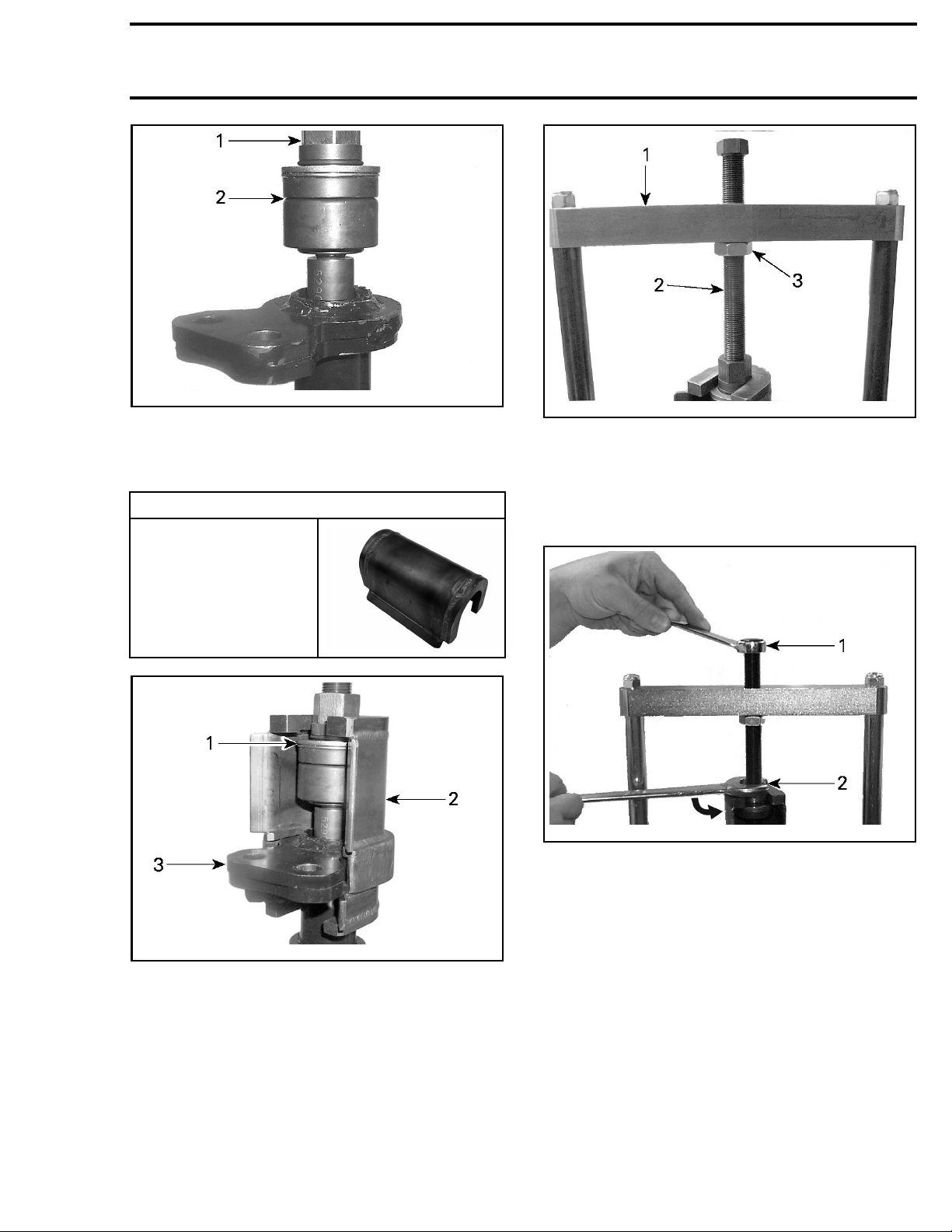
7. Turn the extractor nut down until their is no
space between the extractor and the positioning tip.
532 vmr2015-142
Page 23
Section 07 CHASSIS
Subsection 03 (DYNAMIC POWER STEERING (DPS))
vmr2012-039-026_b
1. Extractor nut
2. No space here
8. Install the universal Pitman arm puller over the
Pitman arm and the extractor thrust bearing.
REQUIRED
PITMAN ARM PULLER
(P/N 529 036 227)
TOOL
vbs2011-015-008_a
1. Jig upper bar
2. Positioning screw
3. Lock nut
10. As you hold the positioning screw steady, turn
the extractor nut up to pull the Pitman arm off
the DPS output shaft.
vmr2012-039-029_a
ioning screw (held steady)
1. Posit
2. Extractor nut (turned up )
11. Remove Pitman arm puller.
12. Unscrew positioning screw.
12-039-028_a
vmr20
1. Extractor thrust bearing
2. Pitman arm puller
an arm
3. Pitm
9. Lock the positioning screw by screwing the
13. Remo
Pitman Arm Installation
1. Ins
scr
ve Pitman arm from the DPS shaft.
tall Pitman arm jig in a vise with positioning
ew upward.
lock nut tightly against jig upper bar.
NOTE
to p
ada
vmr2015-142 533
: Be sure to hold the position screw steady
revent its tip from backing off the positioning
pter.
Page 24
Section 07 CHASSIS
Subsection 03 (DYNAMIC POWER STEERING (DPS))
REQUIRED TOOL
PITMAN ARM JIG
(P/N 529 036 22
2. Apply antizeize lubricant on DPS output shaft
splines; completely cover all the splines with a
light coat.
5)
PRODUCT
LOCTITE 767
DPS output shaft splines
(ANTISEIZE
LUBRICANT) (P/N 293
800 070)
3. Place Pitman arm on DPS shaft as per following
illustration.
NOTE: Be sure to correctly align the Pitman arm
shaft key with the keyway (ground off splines) on
the DPS output shaft.
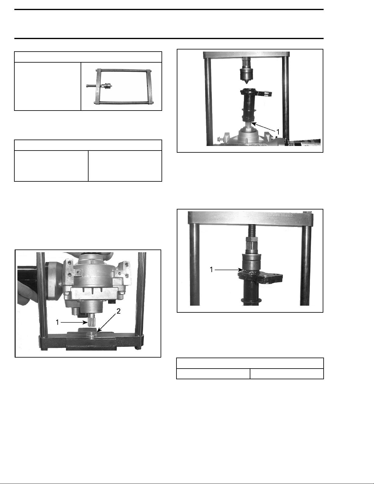
4. Insert the DPS input shaft in the Pitman arm jig
receptacle with the Pitman arm facing up.
vmr2012-039-030_a
1. Spline keyway alignment here
5. Turn the jig positioning screw until the alignment point m akes proper contact with the Pitman arm.
NOTE: Ensure positioning screw is centered in
Pitman arm tube.
2-039-031_a
vmr201
1. Ensure proper contact here
6. Turn the positioning screw to push the Pitman
arm on the DPS output shaft until it bottoms out
on the DPS output shaft nut.
vmr2012-039-025_a
1. DPS i
2. ShaftreceptacleinPitmanarmjig
534 vmr2015-142
nput shaft
NOTE: Ensure specified torque is applied.
TIGHTENING TORQUE
Positioning screw torque 50 N•m (37 lbf•ft)
Page 25
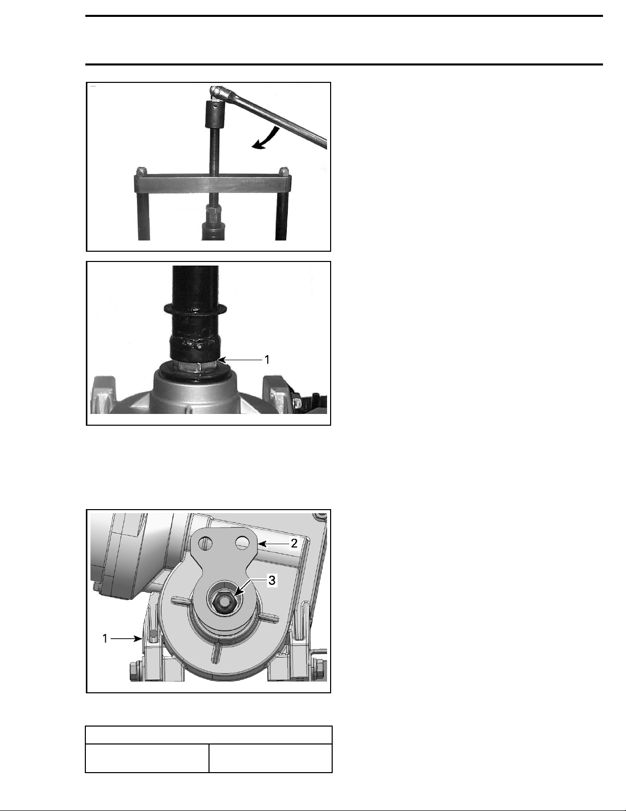
vmr2012-039-032_a
Section 07 CHASSIS
Subsection 03 (DYNAMIC POWER STEERING (DPS))
9. Carry out a steering alignment as described in
this subsection.
vmr2012-039-033_a
1. Ensure proper contact here
7. Unscrew positioning screw and remove pusher
adapter and pull out DPS unit.
8. Install Pitman arm retaining washer and nut.
Tighten nut as specified.
vmr2012-039-022_a
1. DPS
2. Pitman arm
3. Pitman arm nut and washer
TIGHTENING TORQUE
Pitman arm retaining nut
vmr2015-142 535
72.5 N•m ± 7.5 N•m
(53lbf•ft ±6lbf•ft)
 Loading...