

Page 1
Subsection XX (DIGITALLY ENCODED SECURITY SYSTEM (D.E.S.S.))
DIGITALLY ENCODED SECURITY
SYSTEM (D.E.S.S.)
GENERAL
SYSTEM DESCRIPTION
The ignition key contains a ROM chip with a
unique digital code that is the equivalent of a
unique teeth pattern on a conventional key.
When the ignition key is turned ON, the ECM
reads the ignition key and, if it is not recognized,
no engine starting will be possible.
NOTE: When a key is not recognized by the ECM,
INVALID KEY will be displayed in the multifunction
speedometer.
NOTE: All ignition keys have the same teeth
pattern. Therefore, they can be used and turned
in the switch of any D.E.S.S.-equipped vehicle.
However, unless the D.E.S.S. system recognizes
(in the ECM) a valid programmed key, the engine
starting will not be allowed.
NOTE: Actually, it is the memory of the ECM that
is programmed to recognize the digital code of the
ignition key.
Up to 10 ignition keys may be programmed in the
memory of the ECM. They can also be erased individually or all at once.
Note that the D.E.S.S. circuitry is already activated
on all new ECM.
2. Turn ignition switch to ON using any of the key
provided with the vehicle. DO NOT start the
engine.
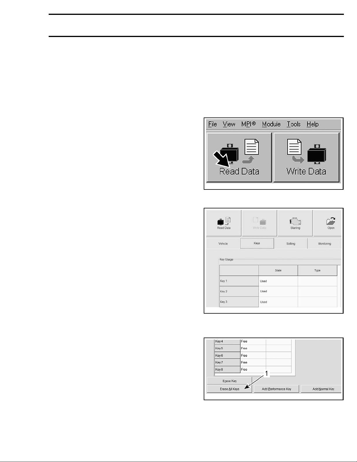
3. Click the Read Data button in B.U.D.S.
vmr2006-012-100_aen
4. Click on K
eys tab.
TROUBLESHOOTING
DIAGNOSTIC TIPS
NOTE: It is a good practice to check for fault
codes using B.U.D.S. as a first troubleshooting
step.
If D.E.S.S. key is not recognized by the ECM, key
is defective or there is a wiring problem, CHECK
ENGINE light will turn on and a message will be
displayed in the multifunction speedometer.
tmr2011-029-001
KEYS TAB
5. Click on Erase All Keys button.
PROCEDURES
KEY PROGRAMMING
1. Connect to the latest applicable B.U.D.S. version. Refer to
B.U.D.S.
vmr2013-034 1
COMMUNICATION TOOLS AND
subsection.
tbl2011-001-052_a
1. Click here to erase all keys
6. Click "YES" to confirm the action.
7. Check the color of the key to be programmed.
Page 2
Subsection XX (DIGITALLY ENCODED SECURITY SYSTEM (D.E.S.S.))
KEY KEY TYPE
BLACK key
GRAY key
Performance key
Normal key
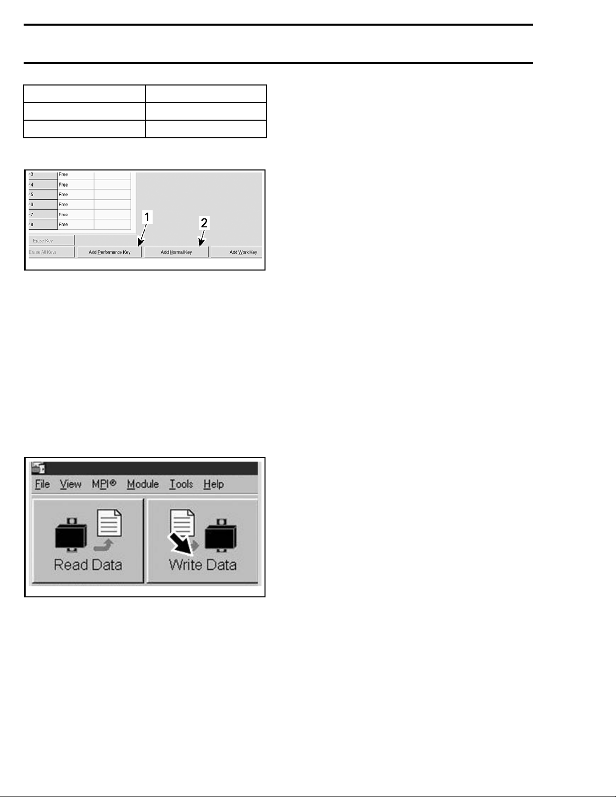
8. Click on the appropriate Add Key button.
tbl2011-001-053_d
1. Add Perfor
2. Add N orm al Key button
mance Key button
NOTE: The Add Work Key button is not used for
these vehicles.
9. Turn ignition switch to OFF.
10. Remove the
key.
11. Insert the next key to be programmed.
12. Turn ignition key to ON position.
13. Click on t
he appropriate Add Key button.
14. Repeat to program more keys if needed.
15. Click on Write Data button to transfer new
settings and information to the ECM.
vmr2006-012-100_ben
WRITE DATA BUTTON
When new data is written in the ECM, a message
that says “Remove key from vehicle” is displayed
in the gauge. When this occurs, remove the key
from ignition switch and wait until the message
disappears.
16. Click on EXIT button to end session.
17. Disconnect all cables and hardware from vehicle.
18. Ensure to reinstall the connector into its housing.
2 vmr2013-034
 Loading...