

Page 1
Subsection 01 (DIAGNOSTIC AND FAULT CODES)
DIAGNOSTIC AND FAULT CODES
GENERAL
MONITORING SYSTEM
The Engine Management System (EMS) features
a monitoring system that self-diagnoses various
electrical and electronic components. This mode
becomes active when the ignition key is turned
ON.
NOTE: Some components require the engine to
be running to be monitored (fuel injectors for example).
The monitoring system continuously validates
that the components (control modules, sensors
and actuators) are not faulty or defective. When
a malfunction is detected, the related electronic
module(s):
– Sets an active fault code.
– Adapts the proper protection strategy accord-
ing to the failure.
– Sends out signals to the multifunction gauge to
inform the rider of a particular condition.
A fault code is an indication that a glitch or malfunction is detected by the monitoring system of
the vehicle.
If a minor fault occurs, the engine and vehicle will
continue to operate without noticeable loss of performance.
If a more i mportant fault occurs, engine RPM may
be limited. The engine/vehicle will continue to operate with reduced performance.
If a major component of the EMS fails, engine
RPM will be limited as well as vehicle speed.
These strategies are used to protect
engine/electrical system from damage and
to maintain safe operation of the vehicle. In extreme cases, the engine may also be completely
shut down.
Pilot Lamps for Problematic
Conditions
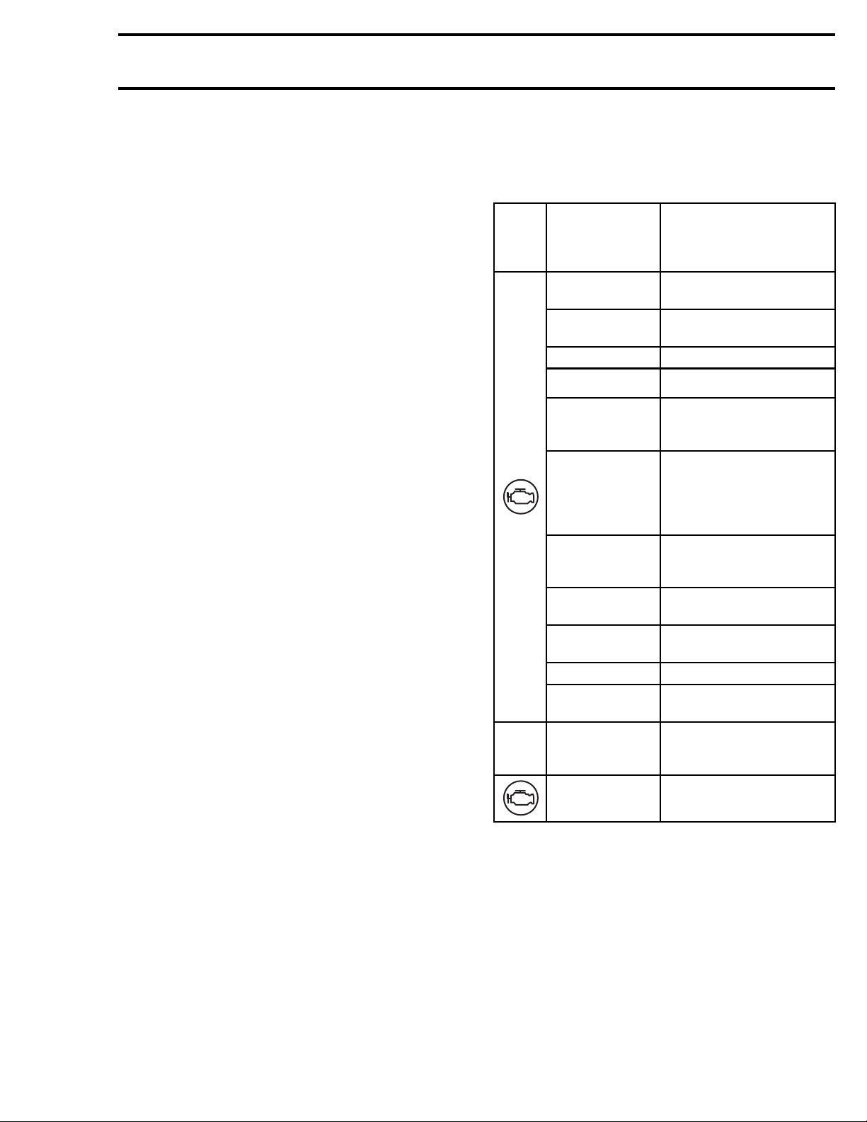
When a problem is detected, a pilot lamp will turn
on or blink in the multifunction gauge. If the fault
that caused the pilot lamp to come on is momentary, the pilot lamp may turn off automatically, or
may need to be reset by powering down the vehicle and then restarting it.
A message may also be displayed to provide additional information related to the fault that turned
on the pilot lamp. Refer to the following chart.
NOTE: In some cases, the CHECK ENGINE message can be displayed along with other messages.
MULTIPILOT
LAMP
FUNCTION
GAUGE
MESSAGE
DESS KEY NOT
RECOGNIZED
BAD KEY
LO BATT VOLT
HIGH BATT VOLT
LOW OIL
PRESSURE
STOP ENGINE
LIMP HOME
MODE
CHECK ENGINE
MAINTENANCE
REQUIRED
ECM NOT
RECOGNIZED
CHECK DPS DPS malfu
TRANSMISSION
SIGNAL FAULT
BRAKE
HI TEMP High engine temperature
Module unable to read the
key
Key not programmed for
the vehicle
Low system voltage
High system voltage
Low engine oil pressure
An importa
management component
is not working properly.
Vehicle pe
purposely limited
An engine management
componen
functioning properly
Periodic maintenance
required
Communication error
between gauge and ECM
Gauge receives an invalid
gear position data
Display
applied for more than 15
seconds (while riding)
CAUSE
nt engine
rformance is
tisnot
nction
ed when brake is
Limp Home Mode
When a major component of the EMS is not operating properly, limp home mode will be set.
Engine RPM will be limited and/or engine behavior and control may be modified depending on the
cause of the failure.
This mode allows the rider to return home, which
would otherwise not be possible without this advanced system.
LIMP HOME will be displayed in the multifunction
gauge and the CHECK ENGINE light symbol will
be on in the gauge.
vmr2016-408 1
Page 2
Subsection 01 (DIAGNOSTIC AND FAULT CODES)
FAULT CODES
Fault C ode Categories
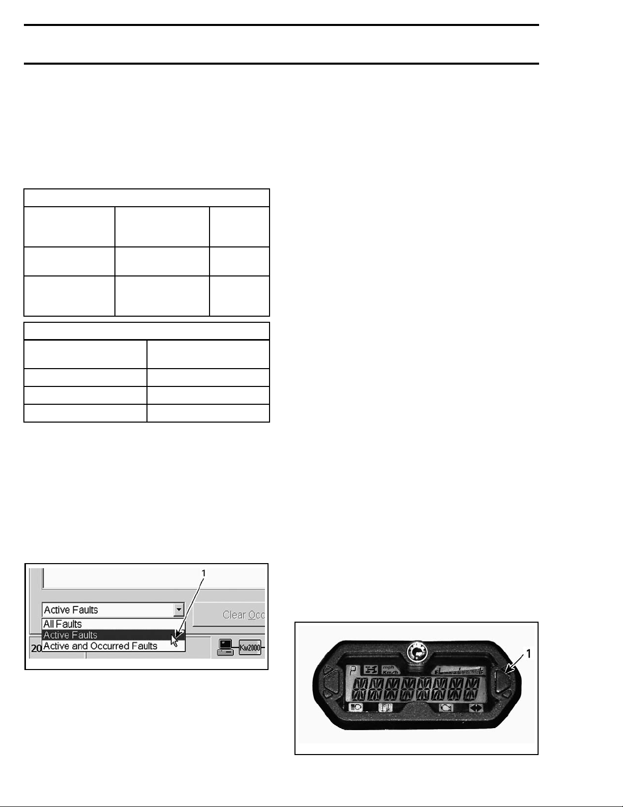
A fault code consists of an alphanumeric designator followed by a hexadecimal number of 3 digits.
The alphanumeric designator defines the category
of the fault code while the hexadecimal number
refers to a unique fault.
FAULT CODE CATEGORIES
ALPHANUMERIC
DESIGNATOR
From P0 to P3
From U0 to U3
RELATED MODULE AND FAULTS
MODULE
ECM
DPS
Cluster
MODULE/
SYSTEM
Power train, TCM
and DPS
Communication
between module
and sensors
FAU L T CO DE
CATEGORY
Fault C ode States
Fault codes have 3 possible states:
–Active
– Occurred
– Inactive.
Click the Fault tab then click on the drop-down list
on the LH lower corner.
Choose the fault code state you want to display.
EXAMPLE
OF FAULT
CODE
P0116
U0073
PandU
PandU
PandU
The active fault may or may not compromise
normal operation of the system(s). Service action should be taken to correct the problem that
caused the fault code.
Once the fault condition(s) of the active fault is no
longer present, its state will change to "occurred".
Occurred Fault Codes
An occurred fault code indicates a fault that was
active, but no longer is.
The occurred fault does not presently affect system or component operation but is retained as a
history of the faults that were detected.
The fault may have been generated due to a
system or component that was momentarily operating outside normal parameters. Repeated
occurred faults of this type should be considered
when troubleshooting a problem, and may require
that maintenance action be taken.
An occurred fault may also be generated when
disconnecting and reconnecting a component, replacing a burnt fuse, when the software update of
an electronic module has been carried out, or may
be due to a momentary high or low voltage.
Inactive Fault Codes
An inactive fault code represents a fault code that
is neither active, nor occurred. It is simply part of
a list of all possible faults that can be monitored
by the ECM and multifunction gauge, which may
become active or occurred if the monitoring system detects an applicable fault. These codes can
be viewed in B.U.D.S.
How to Display Fault Codes in the
Multifunction Gauge
NOTE: A fault code must be in an "Active" state to
be displayed in the multifunction gauge. B.U.D.S.
must be used to read all fault codes states.
1. Use the selector button or mode button and
scroll to Engine Hour (EH) on the gauge.
rmr2011-021-001_a
TYPICAL
1. Drop down list
Active Fault Codes
An active fault code is an indication of a fault that
is currently triggered.
2
07-050-002_c
vmr20
1. Selector button
vmr2016-408
Page 3
Subsection 01 (DIAGNOSTIC AND FAULT CODES)
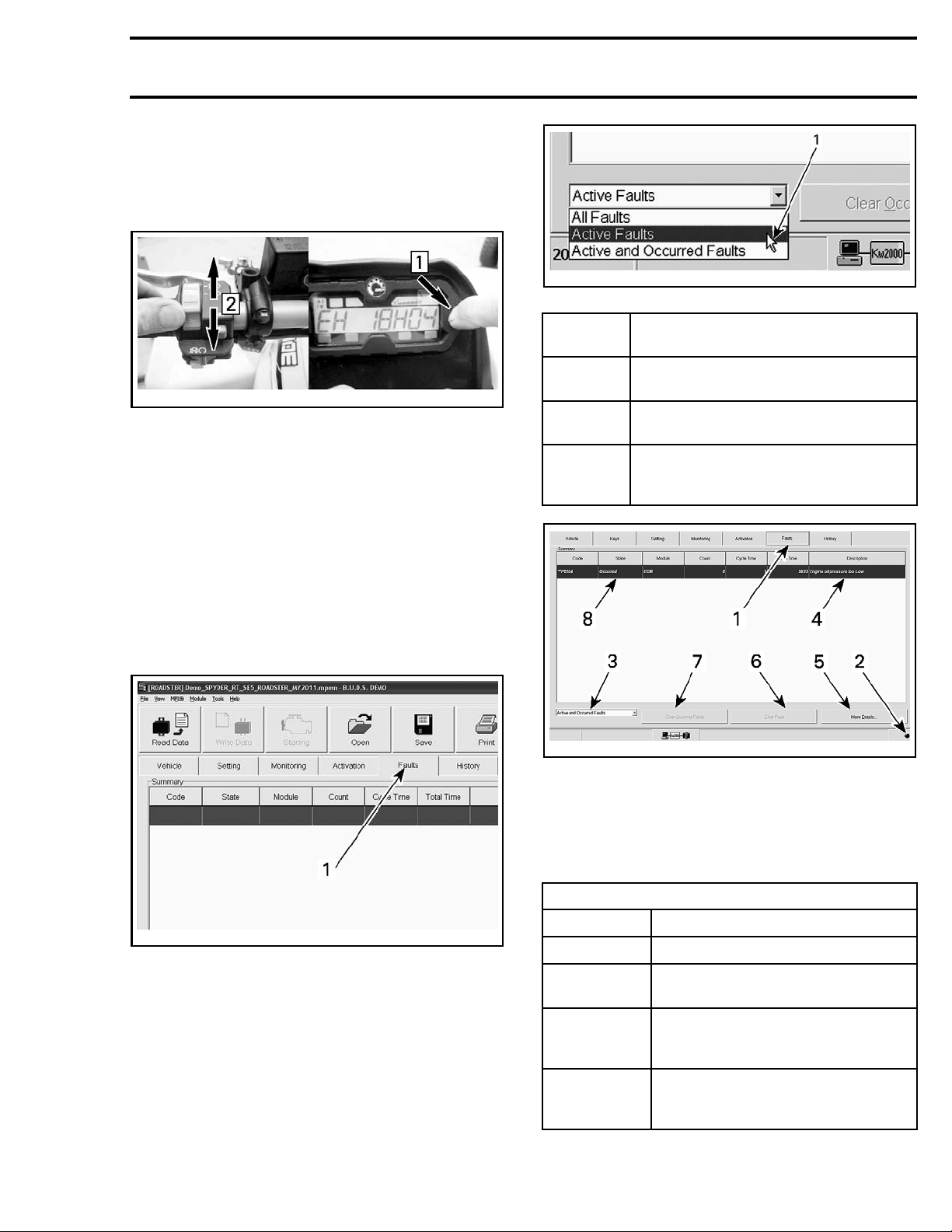
2. Press and HOLD mode button while QUICKLY
toggling HI - LO beam.
NOTE: A minimum of 3 HI - LO toggles must be
completed within 2 seconds.
rmr2011-021-001_a
1. Drop down list
vdd2008-001-097_a
TYPICAL
Step 1: Press and hold
Step 2: Quickly toggle HI - LO beam
How to Read
Fault Codes Using
B.U.D.S.
NOTE: All fault code (regardless of their state) can
be read with B.U.D.S.
1. Connect ve
B.U.D.S. R
AND B.U.D
2. Click on the Read Data button.
3. Click on the Faults tab.
hicle to the latest applicable
efer to
.S.
COMMUNICATION TOOLS
subsection.
FAULT
STATE
All faults
Active
faults
Active and
occurred
faults
vbl2012-007-011_a
FAU LT PAG E
1. Fault t
2. Fault indicator light
3. Fault code state drop box
4. Fault d
5. More Details button
6. Clear Fault button
7. Clear
8. Selected fault
Display all possible faults regardless
of state
Display only faults matching this state
Emptyareaifthereisnoactivefault
Display only faults that have either state
Empty area if there is neither active
nor occur
ab
escription
Occurred Faults button
INFORMATIO
red fault
N
FAULT PAGE DESCRIPTION
rmr2011-070-011_a
1. Fault tab
4. Click on the drop-down list on the LH lower corner.
5. Choose the fault state to display.
vmr2016-408 3
ITEM INFORMATION
Fault tab
t
Faul
indicator light
tcode
Faul
state drop
box
lt
Fau
nomenclature
Click tab to display the fault page
flashing, it indicates there is
When
active fault(s)
Click drop box to select the type of
faults to display
Display specific information and
statistics related to the fault (see
lt nomenclature table)
fau
Page 4
Subsection 01 (DIAGNOSTIC AND FAULT CODES)
FAULTPAGEDESC
RIPTION
ITEM INFORMATION
More Details
button
Clear Fault
button
Clear
Occurred
Faults button
To display possible causes and
service actions related to the
selected fault
To clear occurred faults one at a
time
To clear all occurred faults in relat ed
ECU(s)
When a fault is selected, additional
information pertaining to that
Selected
fault
fault will be displayed when
clicking the "More details" button.
To select a fault, click on the fault
with the mouse or use the cursor up
or down to scroll to the desired fault
FAULT NOMENCLATURE
COLUMN INFORMATION
Fault code number.
When 2 stars (**) precedes the
Code
code, detailed conditions when the
fault occurred, can be displayed by
clicking the "More details" button
rmr2011-021-002_a
SOME COLUMNS REMOVED FOR CLARITY PURPOSE
1. Module that reports a fault
2. Fault description
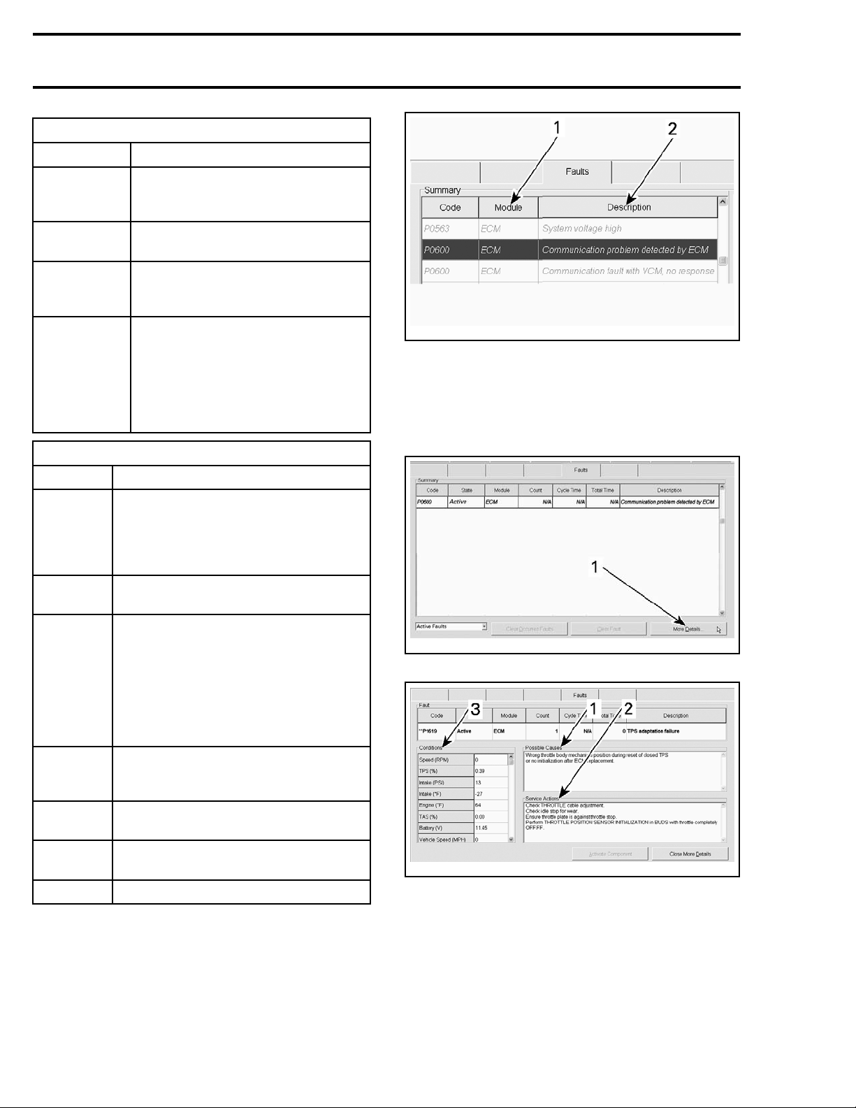
Click on the More Details button, on the RH lower
corner, to display the "Possible Causes" and the
"Service Actions" to step further in the diagnosis.
State
Display the fault state (active, occurred,
inactive)
Displays the module that reports the
fault code. This is the module that
detects or has received a message
Module
of an anomaly and reports it.
List of modules:
- Cluster (multifunction gauge)
- DPS (dynamic power steering)
- ECM (engine control module)
Number of times this fault
Count
occurred within the driving cycle.
Value: From 0 to 255
etime
Cycl
Tota l tim e
Nottobeused.
Value: From 0 to 255 minutes
Nottobeused.
Value: From 0 to 64 255 minutes
Description Provides a short description of the fault
When reading a fault code in B.U.D.S., pay particular attention to which module reports a fault. It
is indicated in the Module column.
The Description column gives a short description
of the fault.
rmr2011-021-050_a
1. Click here
rmr2011-070-002_a
MORE D
1. Possible causes related to the selected fault
2. Service actions
3. Oper
ETAILS PAGE
ating conditions when fault occurred
4
vmr2016-408
Page 5
Subsection 01 (DIAGNOSTIC AND FAULT CODES)
MORE DETAILS PA
ITEM INFORMATION
Possible
causes
Service
actions
Conditions
when fault
occurred
List the possible causes that
triggered the fault
List the possible actions to perform
to solve the fault
List the operating conditions of the
engine and/or vehicle when the fault
was triggere
GE DESCRIPTION
d
How to Clear Fault Codes Using
B.U.D.S.
1. Connect vehicle to the latest applicable
B.U.D.S. software. Refer to
TION TOOLS AND B.U.D.S.
2. Click on the Read Data button.
3. Click on the Faults tab.
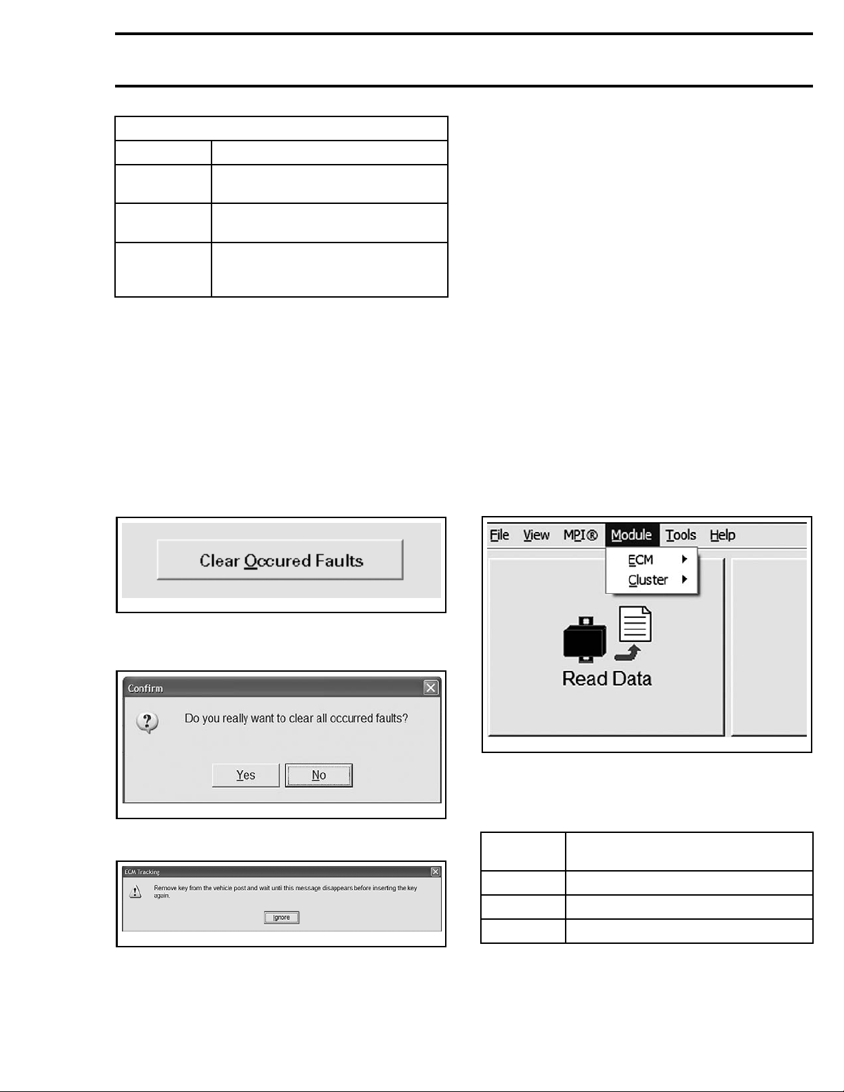
The fault(s) (occurred state only) can be cleared by
pressing the Clear Occurred Faultsor Clear Fault
buttons in B.U.D.S.
COMMUNICA-
subsection.
NOTE: An active fault code cannot be cleared.
In other words, the problem relevant to the fault
code must be repaired before the fault can be
cleared.
FAULT CODE DIAGNOSTIC
Missing M odule
If a module is missing, several fault codes will appear.
To quickly find which module is missing, perform
the following:
1. Connect vehicle to the latest applicable
B.U.D.S. software. Refer to
TION TOOLS AND B.U.D.S.
2. Click on the Read Data button.
3. Click Module in the menu bar.
4. Look at the list of modules.
5. If a module is not visible, then it is not communicating through the CAN bus (controller area
network).
COMMUNICA-
subsection.
rmr2008-039-009
FAULTS PAGE TAB, CLEAR OCCURRED FAULTS
4. Click YES on the following message box.
2-007-013
vbl201
The following message will appear.
vbl2012-007-012
5. Turn ignition OFF and wait until the message
disappears.
This will reset the appropriate counter(s) and will
also record that the problem has been fixed in the
related ECU memory.
lmr2010-019-001
TYPICAL - MODULE SUBMENU LIST
6. Refer to the following table to find the appropriate subsection in this manual to diagnose the
missing module.
MISSING
MODULE
ECM
Cluster
DPS
SECTION TO REFER TO
ELECTRONIC FUEL INJECTION (EFI)
LIGHTS, GAUGE AND ACCESSORIES
DYNAMIC POWER STEERING (DPS)
Diagnostic Tips
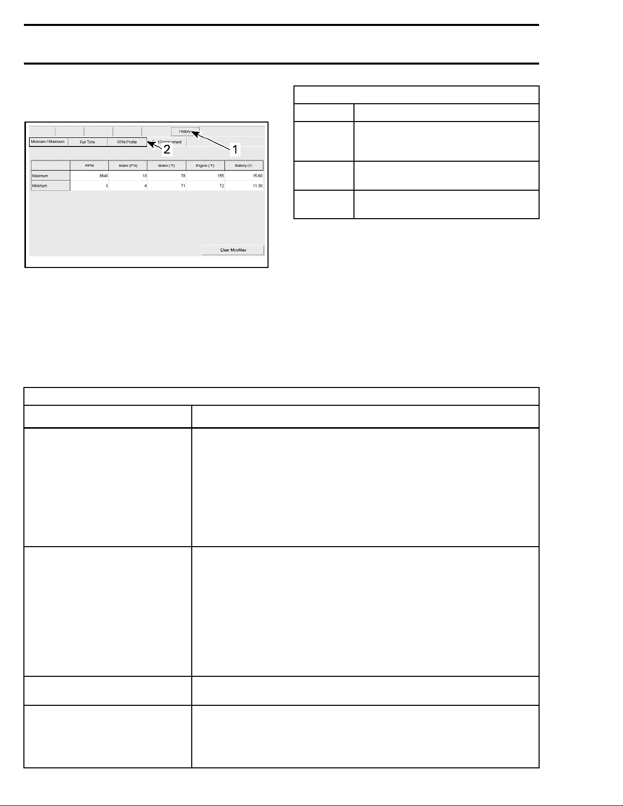
To see the last minute of operating conditions,
click on the History tab in B.U.D.S.
vmr2016-408 5
Page 6
Subsection 01 (DIAGNOSTIC AND FAULT CODES)
NOTE: The page displays data whatever there is
fault code(s) or not.
rmr2011-070-003_a
1. History tab
2. Additional history pages
HISTORY PAGE DE
ITEM INFORMATION
Minimum/
Maximum
Run time
RPM
profile
Display the minimum and maximum
values encountered. Click "Clear
Min/Max" to reset the values
Display the time proportion in what
mode the engine was running in
Display the RPM range proportion in
which the engine was running in
SCRIPTION
When a minor fault occurs:
– Turn ignition key OFF.
– Wait 30 seconds.
– Turn ignition key ON.
This should change the fault state from "Active" to
"Occurred".
The vehicle should then operate normally.
If a sensor-related fault persists, you may try
disconnecting/reconnecting the sensor.
Read the f ollowing for a general approach to trou-
bleshoot fault codes (active or occurred).
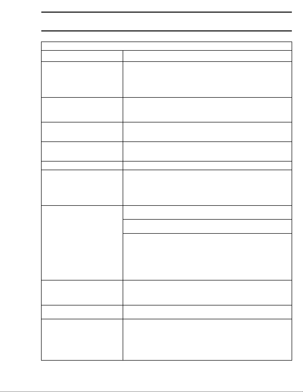
GENERAL GUIDELINES TO SOLVE FAULT CODES
CONDITION ACTION
Troubleshooting vehicle
New fault(s) appear after a vehicle
maintenance or repair
Commu
"Occurred" after module flashing
nication faults displayed as
Use B.U.D.S. to:
Read fault codes.
Display "
Display "Occurred" faults to troubleshoot intermittent problems.
Monitor system(s), sensor(s), switches and actual conditions.
Activat
Set components (resets etc).
Know the last minute of operating conditions by using the "History" page.
Know the
using the "More details" button in the fault page.
Check se
Before vehicle maintenance:
Read th
After vehicle maintenance:
Read th
Compare the fault code(s) before and after the maintenance
using the printed copy and the current B.U.D.S. reading.
Inves
Clear all occurred faults in B.U.D.S.
Normal behavior when flashing a module.
Clear all occurred faults and check again.
Active" faults to see components currently not operating normally.
e component(s) for troubleshooting.
operating conditions, if available, when a fault code occurred by
nsor connections or mixed up connections.
e electronic modules with B.U.D.S.
e electronic modules with B.U.D.S.
tigate only the newly fault codes.
Read t
Click on the "More Details" button.
Sensor "Active" fault
6 vmr2016-408
Look at the "Conditions" when available.
Read
Apply the "Service Actions".
he fault description in B.U.D.S.
the "Possible Cause s".
Page 7
Subsection 01 (DIAGNOSTIC AND FAULT CODES)
GENERAL GUIDEL
CONDITION ACTION
Low system voltage
on one module.
Power problem on sensor(s)
Low system voltage
on several modules
(several co
mmunication faults
will also appear)
High system voltage on several
modules
When all modules report that a
module is missing
When several modules are in fault
CAN bus OFF
INES TO SOLVE FAULT CODES
Check related
fuse(s) and relay.
Check related power and ground wires.
Check for common power supply to several sensors/modules
(refer to
ER DISTRIBUTION AND GROUNDS)
POW
.
NOTE: Some sensors are supplied by the battery while others are
supplied by a mo dule.
Check battery condition and connections.
Check related fuse(s) and relay.
Check voltage regulator/rectifier.
Abatteryc
harger has likely been used to substitute the vehicle battery.
Clear all occurred faults and check again.
Check voltage regulator/rectifier.
Check the module that is reported as missing.
Check related fuse(s) and relay.
Check rela
ted power and ground wires.
Search for a common problem such as a faulty sensor.
When several modules and sensors report that a module is missing.
The missing module may report CAN bus off.
Check rel
ated CAN wires (continuity, short to
ground, short between CAN low and high).
Check module pins and wiring terminals.
Then, th
e other modules should stop reporting that module is missing.
Occurred fault(s)
Fault cou nt
(0 - 255)
Fault conditions
(more details button)
Hard to find problems
May have been generated due to a system or component that was
momenta
rily operating outside normal parameters.
May be generated when disconnecting and reconnecting a component,
ing a burnt fuse, or may be due to a momentary high or low voltage.
replac
Before being "Occurred", a fault has always been "Active"
for a ce
rtain time, indicating that an unexpected condition
or problem has been present during the driving cycle.
A frequent momentarily fault or an intermittent fault may never
be seen
as "Active" in B.U.D.S. while there is still a pending problem.
This type of malfunctions can be discovered by looking at
the "Occurred" faults and then by evaluating the fault count.
gasafaultispresent,itisdisplayedas"Active".
As lon
Low value: Suggests handling problems
ections, terminal c ontact/shape etc.).
(conn
High value: Suggests a frequent and unsolved problem.
The problem should be investigated.
for abnormal, excessive values.
Look
When the basic troubleshooting has been done and the fault
code(s) persists, often the problem is related to the wiring
ness, connections or electromechanical components.
har
Short to ground, to battery or between wires.
Wire splices, chafing, terminal problems
lled out, bent, out of shape, corroded etc.).
(pu
Badcontactsinswitchorrelay.
vmr2016-408 7
Page 8
Subsection 01 (DIAGNOSTIC AND FAULT CODES)
ECUs share information and t heir systems may interact with each other. Certain faults may cause more
than one ECU to set a fault code or indication (pilot lamp or message) as the failure of some components
may affect the operation of several systems.
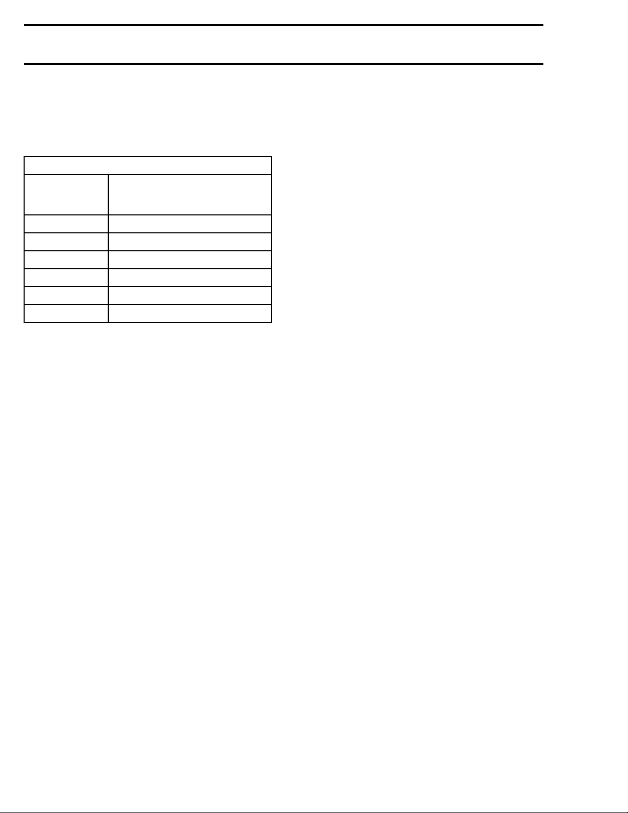
FAULT CODE TABLE
ACRONYMS USED IN THE FAULT CODE TABLE
USED IN
FAULT CODE
TABLE
ECM Engine Control Module
DPS Dynamic Power Steering
CAN Controller Area Network
TPS Throttle Position Sensor
GBPS Gearbox Position Sensor
SCM Suspension Control Module
MEANING
HOW TO FIND FAULT CODE
DESCRIPTIONS
For the latest fault code table, use the Info Center submenu in BOSSWeb and enter the following
search criteria:
– Enclose the search within quotes " "
– Enter: "ATV DTC (All engines) 2016".
8 vmr2016-408
 Loading...