

Page 1
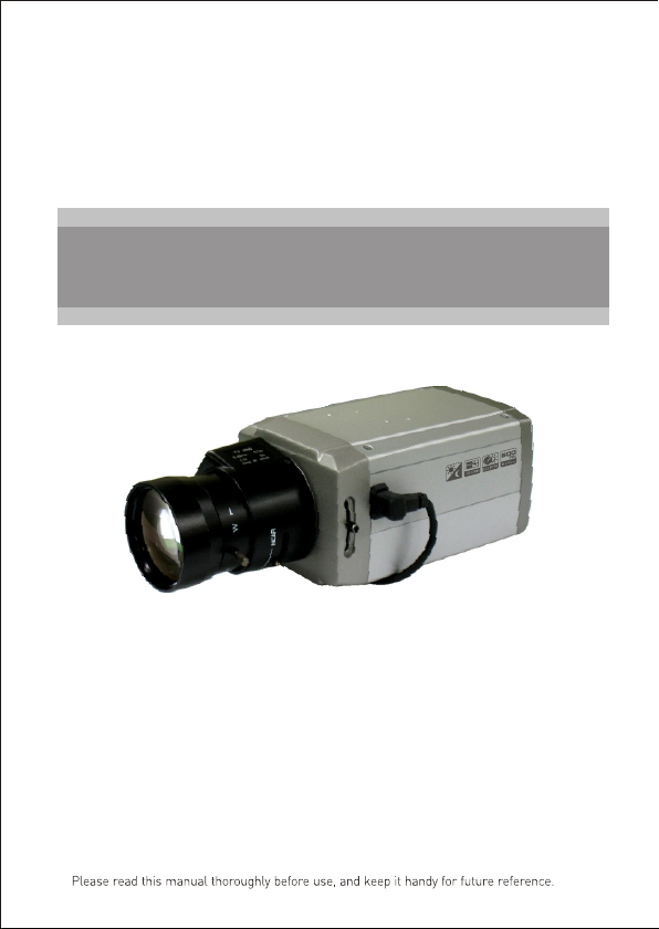
INSTRUCTION MANUAL
Ultra
High Resolution
Color Came ra
a
D
y h a
A Hi-R
TR
UL e
C
/Nig t
s
a
r
me
Page 2
WARNINGS AND CAUTIONS:
TO REDUCE THE RISK OF FIRE OR ELECTRIC SHOCK, DO NOT EXPOSE THIS PRODUCT TO RAIN OR
MOISTURE. DO NOT INSERT ANY METALLIC OBJECTS THROUGH THE VENTILATION GRILLS OR
OTHER OPENINGS ON THE EQUIPMENT.
CAUTION:
CAUTIONCAUTION
CAUTION: TO REDUCE THE RISK OF ELECTRIC SHOCK,
DO NOT REMOVE COVER(OR BACK).
NO USER-SERVICEABLE PARTS INSIDE.
REFER SERVICING TO QUALIFIED SERVICE PERSONNEL.
EXPLANATION OF GRAPHICAL SYMBOLS
The lightning flash with arrowhead symbol, within an equilateral triangle, is
intended to alert the user to the presence of uninsulated "dangerous voltage"
within the product's enclosure that may be of sufficient magnitude to constitute a
risk of electric shock to persons.
The exclamation point within an equilateral triangle is intended to alert the user to
the presence of important operating and maintenance (servicing) instructions in the
literature accompanying the product.
PRECAUTIONS
Safety ----------------------------------------- Installation -----------------------------------
Should any liquid or solid object fall into the cabinet,
unplug the unit and have it checked by the qualified
personnel before operating it any further.
Unplug the unit from the wall oulet if it is not going to
be used for several days or more. To disconnect the
cord, pull it out by the plug. Never pull the cord itself.
Allow adequate air circulation to prevent internal heat
build-up. Do not place the unit on surfaces (rugs,
blankets, etc.) or near materials(curtains, draperies)
that may block the ventilation holes.
Height and vertical linearity controls located at the
rear panel are for special adjustments by qualified
personnel only.
Do not install the unit in an extremely hot or
humid place or in a place subject to excessive
dust, mechanical vibration.
The unit is not designed to be waterproof.
Exposure to rain or water may damage the unit.
Cleaning --------------------------------------
Clean the unit with a slightly damp soft cloth.
Use a mild household detergent. Never use
strong solvents such as thinner or benzine as
they might damage the finish of the unit.
Retain the original carton and packing
materials for safe transport of this unit in the
future.
ii
Page 3
FCC COMPLIANCE STATEMENT
FCC INFORMATION : THIS EQUIPMENT HAS BEEN TESTED
AND FOUND TO COMPLY WITH THE LIMITS FOR A CLASS A DIGITAL
DEVICE, PURSUANT TO PART 15 OF THE FCC RULES. THESE
LIMITS ARE DESIGNED TO PROVIDE REASONABLE PROTECTION
AGAINST HARMFUL INTERFERENCE WHEN THE EQUIPMENT IS
OPERATED IN A COMMERCIAL ENVIRONMENT. THIS EQUIPMENT
GENERATES, USES, AND CAN RADIATE RADIO FREQUENCY
ENERGY AND IF NOT INSTALLED AND USED IN ACCORDANCE WITH
THE INSTRUCTION MANUAL, MAY CAUSE HARMFUL INTERFERENCE
TO RADIO COMMUNICATIONS. OPERATION OF THIS EQUIPMENT IN
A RESIDENTIAL AREA IS LIKELY TO CAUSE HARMFUL
INTERFERENCE IN WHICH CASE THE USER WILL BE REQUIRED TO
CORRECT THE INTERFERENCE AT HIS OWN EXPENSE.
CAUTION : CHANGES OR MODIFICATIONS NOT EXPRESSLY
APPROVED BY THE PARTY RESPONSIBLE FOR COMPLIANCE
COULD VOID THE USER'S AUTHORITY TO OPERATE THE EQUIPMENT.
THIS CLASS A DIGITAL APPARATUS COMPLIES WITH CANADIAN
ICES-003.
NORME NMB-003 DU CANADA.
CE COMPLIANCE STATEMENT
WARNING
This is a Class A product. In a domestic environment this product
may cause radio interference in which case the user may be required
to take adequate measures.
iii
Page 4

IMPORTANT SAFEGUARDS
1. Read these instructions.
2. Keep these instructions.
3. Heed all warnings.
4 . Follow all instructions.
5. Do not use this apparatus near water.
6. Clean only with dry cloth.
7. Do not block any ventilation openings. Install in accordance with the
manufacturer's instructions.
8. Do not install near any heat sources such as radiators, heat registers,
stoves, or other apparatus (including amplifiers) that produce heat.
9. Do not defeat the safety purpose of the polarized or grounding-type
plug. A polarized plug has two blades with one wider than the other.
A grounding type plug has two blades and a third grounding prong.
The w id e bl ad e or t he t hi rd p ro ng a re p ro vi de d fo r yo ur s af et y. If t he
provided plug does not fit into your outlet, consult an electrician for
replacement of the obsolete outlet.
10.Protect the power cord from being walked on or pinched particularly
at plugs, convenience receptacles, and the point where they exit from
the apparatus.
11. On ly u se a tt ac hm en ts /a cc es so ri es s pe ci fi ed b y th e ma nu fa ct ur er.
12. Use only with the cart, stand, tripod, bracket, or table specified by the
manufacturer, or sold with the apparatus. When a cart is used, use
caution when moving the cart/apparatus combination to avoid injury
from tip-over.
13. Unplug this apparatus during lightning storms or when unused for
long periods of time.
14. Refer all servicing to qualified service personnel. Servicing is
required when the apparatus has been damaged in any way, suc h as
power-supply cord or plug is damaged, liquid has been moisture, does
not operate normally, or h as b ee n dr op pe d.
15. CAUTION THESE SERVICING INSTRUCTIONS AR E FO R US E BY
QUALIFIED SERVICE PERSONNEL ONLY. TO R ED UC E TH E RI SK
OF ELECTRIC SHOCK DO NOT PERFORM AN Y SERVICING OTHER
THAN THAT CO NTA IN ED I N TH E OP ER ATING INSTRUCTIONS
UNLESS YO U QR E QU AL IF IE D TO D O SO .
16. Use Certified/Listed Class 2 power source only.
iv
Page 5

TABLE OF CONTENTS
INTRODUCTION 1
CAMERA OVERVIEW 2
CONTENTS OF PACKAGE 3
CAMERA ADJUSTMENT 3
CONTROL AND CONNECTIONS / DAY&NIGHT INPUT TERMINALS 8
LENS 10
SPECIFICATIONS 11
v
Page 6

INTRODUCTION
The camera provides high-quality images using SONY CCD technology especially
designed for closed-circuit television (CCTV) and security surveillance
applications.
Features:
High resolution and high performance 1/3" SONY Super HAD CCD
Technology
Excellent picture quality
600 lines(Color) of resolution
0.1 lux(Color), 0.04 lux(B/W) @ F1.2 50IRE Sensitivity
(Sense up x 256 -
Auto electronic shutter [1/60(1/50) ~ 1/120,000] and manual electronic
shutter modes
OSD (On Screen Display)
3D DNR Function
Eclipse
DRC (Dynamic Range Control)
Auto and manual white balance modes
BLC (Back Light Compensation)
Day&Night (Auto / DAY / NIGHT / EXT)
Private Mask (24 position, BW, Color, Mosaic)
AGC (Auto Gain Control)
Sense-up (x2 ~ x256)
MIRROR (NORMAL /MIRROR/VERTICAL /ROTATE)
VIDEO OUT(BNC,UTP(option))
Motion Detection
Internal / AC line lock
RS485 CONTROL
Compatible with video or DC - type lens with OSD select.
Quick connect for video or DC lens with 4-pin connector.
Operates in 12 VDC or 24 VAC
Use Certified / Listed Class 2 power supply only.
0.0004 lux(Color), 0.0001 lux(B/W))
(EXT : D&N With ICR model option)
1
Page 7

CAMERA OVERVIEW
120.0mm
1/4-20UNC
REAR VIEW
1
5
10
< W / O UTP M ode l >
3
1
5
10
3
66.0mm
2
2
4 6
4 6
1-32UNEF
SIDE VIEW
FRONT VIEW
56.0mm
7.0mm
1
Left Button
2
Up Button
3
7
8
7
8
9
Enter Button
4
Right Button
5
Down Button
Day / Night External Input
6
ALARM OUT
RS - 485
UTP Video Output(option)
Power Indicator
7
Video Out Connector (BNC)
8
UTP or BNC Transformation Switch (option)9
AC/DC Compatible Input Terminal
10
9
* , - UTP Option6
BOTTOM VIEW
Terminal
Block
43.0mm
14.0mm
< W / UTP M ode l >
2
Page 8

CONTENTS OF PACKAGE
Installation of the camera must be performed by qualified service personnel in accordance
with all local and national electrical and mechanical codes.
Carefully remove the color camera and its accessories from the carton
and verify that they were not damaged in shipment.
The contents of the package includes:
1. Color CCD camera
2. Mini-DIN connector (for video-or dc-type auto-iris lens)
3. CS adapter ring for C mounting “C” lenses
4. This manual
CAMERA ADJUSTMENT
OSD MAIN SCREEN
- [ENTER] ON or OFF of OSD MENU
- [UP] / [DOWM] UP or DOWN of Cursor
- [LEFT] / [RIGHT] SUB MENU ON or Decision
1) EXPOSURE, WHITE BAL, DAY/NIGHT, MOTION, PRIVACY, OPTION and
DISPLAY has a SUB MENU. [UP]/[DOWN] of Cursor.
And SUB MENUS is displayed by [LEFT] / [RIGHT].
2) SYNC : AUTO or INT can be selected.
3) When making INITIAL from USER to DEFAULT, all data is initialized.
4) To EXIT the menu use the [LEFT] / [RIGHT] buttons when EXIT is highlighted.
M ENU
▶
EXPOSURE
WHITE BAL
DAY/NIGHT
MOTION
PRIVACY
OPTION
DISPLAY
SYNC
INITIAL
EXIT
+…
+…
+…
+…
+…
+…
+…
A U T O
D EF AU LT
3
Page 9

M ENU
▶
EXPOSURE
WHITE BAL
DAY/NIGHT
MOTION
PRIVACY
OPTION
DISPLAY
SYNC
INITIAL
EXIT
EXPOSURE
▶
LENS
BRIGHTNESS
BACKLIGHT
SHUTTER
AGC
SENSE UP
ECLIPSE
3D-DNR
DRC
RETURN
WHITE BAL
▶
WB MODE
RED CONT
BLUE CONT
PUSH AUTO
RETURN
DAY/NIGHT
▶
D/N MODE
AUTO LEVEL
FILTER DLY
SEN OR
S IN
BURST
RETURN
OPTION
▶
TITLE
NEGA/POSI
SHARPNESS
MIRROR
ZOOM
PAN/TILT
PHASE
RETURN
MOTION
DETECT MODE
▶
DETECT AREA
SENSITIVITY
ALARM TIME
RETURN
DISPLAY
▶
TITLE
MOTION DET
CAMERA ID
PROTOCOL
BAUDRATE
SAVE
RETURN
**SEN SO R IN : On ly D &N w ith I CR m od el
4
PRIVACY
▶
AREA
MASK
MODE
LEVEL
TOP
DOWN
LEFT
RIGHT
RETURN
Page 10

<EXPOSURE>
Press the [LEFT] or [RIGHT] button to access the "EXPOSURE" mode.
1) LENS
2) BRIGHTNESS
3) BACKLIGHT
4) SHUTTER
5) AGC
6) SENSE UP
7) ECLIPSE
8) 3D-DNR
9) DRC
10) RETURN
<WHITE BALANCE>
Press the [LEFT] or [RIGHT] button to access the "WHITE BALANCE" mode.
1) WB MODE
- ATW
- AWC
- MANUAL
- INDOOR
- OUTDOOR
2) RED CONT
3) BLUE CONT
4) PUSH AUTO
5) RETURN
DC, Video, ELC can be selected.
0 to 60 can be selected.
Level setting is available in DC, Video, ELC mode.
*
ON or OFF can be selected. (BLC level, location)
Prevents such a back light effect to secure a clear image under
*
all illumination environments.
1/60 (1/50), FLC, 1/250, 1/500, 1/1000, 1/2000, 1/4000,1/10000
1/30000, 1/60000, 1/120000 sec.
When LENS is DC or VIDEO, it is possible to select it.
*
Another becomes NOT USE.
AGC OFF, LOW, MID, HIGH can be selected.
As the level of gain increases, the screen gets brighter and the level
*
Of noise also increases.
OFF, x2, x4, x8, x16, x32, x64, x128, x256 can be selected.
SENSE UP helps maintain a bright, clear screen image
*
by automatically detecting change in the level of light
ON or OFF can be selected.
The function improves the identification capability of subjects facing
*
a brightly lit situation by filtering out the strength of the light.
OFF, LOW, MID, HIGH can be selected.
Reduces the noise on the screen under low light condition
*
ON or
OFF
The function to visibly brighten a subject in a dark area
*
Return to MAIN MENU.
This mode can be used within the color temperature range
1.800°K ~ 10.500°K
Please press the [LEFT] or [RIGHT] button in the PUSH AUTO mode
while the camera is directed at a piece of while paper to obtain the
optimum state under current illumination.
If the environment including the light source is
changed, you have to adjust the White balance again.
Manual mode. User can change R and B Gain manually.
Set the color temperature to 3200˚K
Set the color temperature to 6300˚K
Adjust Red Gain Value (0 ~ 127)
Can be adjust while in manual mode.
Adjust BLUE Gain Value (0 ~ 127)
Can be adjust while in manual mode.
When it is AWC, OFF to PUSH can be selected.
Return to MAIN MENU.
5
Page 11

<DAY/NIGHT>
Press the [LEFT] or [RIGHT] button to access the "DAY/NIGHT" mode.
1) D/N MODE
- AUTO
- DAY
- NIGHT
- EXT
2) AUTO LEVEL
3) FILTER DLY
4) SENSOR IN
5) BURST
6) RETURN
<MOTION>
Press the [LEFT] or [RIGHT] button to access th "MOTION"mode.
1) DETECT MODE
2) DETECT AREA
3) SENSITIVITY
4) ALARM TIME
5) RETURN
<PRIVACY>
Press the [LEFT] or [RIGHT] button to access the “PRIVACY” mode.
1) AREA
2) MASK
3) MODE
4) LEVEL
5) TOP
6) DOWN
7) LEFT
8) RIGHT
9) RETURN
AUTO, DAY, NIGHT, EXT can be selected.
This camera has a function which automatically changes to
the appropriate mode for day-time or night-time.
In this mode, the camera outputs the video image only in color.
In this mode, the camera outputs the video image only in black and white.
In this mode, an external signal changes the camera output from the
COLOR mode to BW mode and back.
*EXT : Only D&N with ICR Model (Option)
When set to AUTO, the 0 to 3 values can be selected.
AGC LOW : 0 AGC MID : 0 ~1 AGC HIGH : 0 ~3
*
When set to AUTO, 4 to 10 can be selected.
When AGC is OFF, NOT USED.
Adjust the delay time of filter movement when changing
*
from on to off or off to on
When it is EXT, No or NC Can be selected.
*SENSOR IN : Only D&n with ICR Model.(Option)
When it is DAY, Not Use.
Another mode be comes ON or OFF can be selected.
Return to MAIN MENU.
ON or OFF can be selected.
Turning on becomes invalid while displaying OSD.
*
However, it becomes effective only at MOTION AREA.
MOTION AREA is displayed.
0 to 8 can be selected.
1 to 60 sec can be selected.
Return to MAIN MENU.
1 to 24 can be selected.
ON or OFF can be selected.
When MASK is ON, BW, MOSAIC, COLOR can be selected.
- BW : 0 to 15 can be selected.
- MOSAIC : SMALL or MIDDLE or LARGE can be selected.
- COLOR : RED, BLUE, GREEN, YELLOW, CYAN, MAGENTA
can be selected.
When MASK is ON, 3 to 124(NTSC) or 6 to 150(PAL) can be selected.
When MASK is ON, 5 to 126(NTSC) or 8 to 152(PAL) can be selected.
When MASK is ON, 0 to 187(NTSC) or 0 to 185(PAL) can be selected.
When MASK is ON, 2 to 189(NTSC) or 2 to 187(PAL) can be selected.
Return to MAIN MENU.
.
6
Page 12

<OPTION>
Press the [LEFT] or [RIGHT] button to access the "OPTION" mode.
1) TITLE
A
B
C
TITLE
BS
POS
ABCDEFGH I J KLM
NOPQRSTUVWXYZ
abcdefgh i j k
uvwxyz
s t
nopqr
012 3456 78 9 :
+ - ~
! % ( ) "
#
* /
END
m
l
; .
_
&
A. TITLE
B. Command Line
: Move to left
: Move to right
BS : Erase a left character
POS : Change the position of the title
END : End
C. Charactor Table
: brank
_
: space
2) NEGA/POSI NEGA or POSI can be selected.
3) SHARPNESS 0 to 15 can be selected.
4) MIRROR
- MIRROR Horizontal image inversion
- VERTICAL Vertical image inversion
- ROTATE Horizontal image and Vertical image inversion
5) ZOOM 0FF(x1) and ON1 to ON8(x4) can be selected.
When PAN/TILT is ON, it is NOT USE.
6) PAN/TILT OFF or ON(x2) can be selected.
o p erate by [UP],[DOWN],[LEFT],[RIGHT].
7) PHASE Sync phase is adjustable in line lock mode (Auto mode)
8) RETURN Return to MAIN MENU
NORMAL, MIRROR, VERTICAL, ROTATE can be selected.
* When OSD MENU is OFF and PAN/TILT is ON,
0 ~ 524 (NTSC) or 0 ~ 624 (PAL).
<DISPLAY>
Press the [LEFT] or [RIGHT] button to access the "DISPLAY" mode.
7
Page 13

CONTROL AND CONNECTIONS/DAY&NIGHT
INPUT / ALARM OUT TERMINALS - (UTP MODEL)
<WI TH U TP MO DE L>
1 2 3 4
TP VIDEO OUTPUT D&N
*3Pin : O nl y D&N w it h IC R model o pt ion (DD N mo del : NC)
COM
IN GND
1) CAMERA CONTROL
6 PIN : RS 485+
7 PIN : RS 485
2) DAY&NIGHT INPUT Terminal
To select Day/Night mode using external equipment, connect control line
to the appropriate terminal.
DAY&NIGHT EXTERNAL INPUT (2pin)
It is the function that can be switched to DAY Mode or NIGHT Mode by receiving the
D&N on/off signal from external light sensor or IR LED LAMP. When D&N Mode is set
"EXT” on the OSD menu of the camera.
4
3
) ALARM OUT (5pin)
3
Motion detection signals are output through this port. (OFF : GND, ON : 3.3V)
-
GND
DAY&NIGHT INPUT
4) POWER INPUT TERMINAL
This terminal accepts a DC12V or AC24V power
source from a DC12V or AC24V ac +/-10% 60/50Hz +/- 1Hz.
CLASS 2
+ DC 12V ~ AC 24V ~
Use Certified/Listed Class 2 power supply only.
In DC power, use the Adapter mode than DC 12V
500mA Capacity.
5
ALARM
OUT
6 7
RS 485+(RX)
RS-485
RS 485-(TX)
(Onl y D& N wi th I CR model opti on )
Open contact : DAY
Close contact : NIGHT
5) VIDEO OUT CONNECTOR
BNC : This BNC connector provides a 1.0Vp-p/75 ohms composite video Signal.
UTP : Unshielded Twisted Pair video Transmission for effective installation(option).
1PIN : TP VIDEO OUTPUT
2PIN : TP VIDEO OUTPUT
8
Page 14

CONTROL AND CONNECTIONS/DAY&NIGHT
INPUT / ALARM OUT TERMINALS - (W/O UTP MODEL)
<W/ O UT P MOD EL >
*1Pin : O nl y D&N w it h IC R model o pt ion (DD N mo del : NC)
1) CAMERA CONTROL
4 PIN : RS 485+
5 PIN : RS 485
2) DAY&NIGHT INPUT Terminal
To select Day/Night mode using external equipment, connect control line
to the appropriate terminal.
DAY&NIGHT EXTERNAL INPUT (2pin)
It is the function that can be switched to DAY Mode or NIGHT Mode by receiving the
D&N on/off signal from external light sensor or IR LED LAMP. When D&N Mode is set
"EXT” on the OSD menu of the camera.
2
1
) ALARM OUT (3pin)
3
Motion detection signals are output through this port. (OFF : GND, ON : 3.3V)
4) POWER INPUT TERMINAL
1 2
COM
D&N
IN GND
-
GND
DAY&NIGHT INPUT
CLASS 2
+ DC 12V ~ AC 24V ~
3
ALARM
OUT
4 5
RS 485+(RX)
RS-485
RS 485-(TX)
(Onl y D& N wi th I CR model opti on )
Open contact : DAY
Close contact : NIGHT
This terminal accepts a DC12V or AC24V power
source from a DC12V or AC24V ac +/-10% 60/50Hz +/- 1Hz.
Use Certified/Listed Class 2 power supply only.
In DC power, use the Adapter mode than DC 12V
500mA Capacity.
5) VIDEO OUT CONNECTOR
BNC : This BNC connector provides a 1.0Vp-p/75 ohms composite video Signal.
9
Page 15

LENS
The lens is not supplied with this camera. Purchase a lens suitable for your environment.
This camera accepts the auto iris lens and both C-and CS-mount lens.
* Notes *
For using main functions it is recommended to use Auto Iris Lens with DC type.
If the lens is marked with fingerprints other marks, the image quality might be poor.
It is recommended to use a high quality lens to improve the image quality under
low illumination.
<INSTALLING AUTO IRIS LENS>
1. Remove the cover from the iris lens plug supplied, and solder the lens cable to the plug as
shown below.
Video type :
Pin 1 --- Red (Power source)
Pin 2 --- N.C
Pin 3 --- White (Video signal)
Pin 4 --- Black (GND)
Pin 4
Connector
Cover
Heat
Shrinkable
Tubes
Pin 3
Rib
Pin 1
Pin 2
2. Remove the protective cap, and attach the lens to the camera by turning clockwise.
DC type :
Pin 1 --- DampingPin 2 --- Damping+
Pin 3 --- Drive+
Pin 4 --- Drive-
Connector
Automatic
Iris Lens
Iris Control
Cable
10
Page 16

SPECIFICATIONS
MODEL
Power sou rce
POWER
Power con sumption
Image sen sor
Total number of pix els
Scannin g system
Scannin g frequenc y
Sync. sys tem
Electro nic shutte r
Resolut ion
Min. illu mination
Video outp ut
S/N Ratio
Camera Co ntrol
Auto Expo sure
G
Lens
E
N
BLC
E
AGC
R
Sense-u p
A
Eclipse
L
3D-DNR
DRC
F
White Bal ance
U
Day & Night
N
Motion de tection
Privacy z one
C
Display Titl e
T
Video Pict ure
I
Brightn ess
O
Sharpne ss
N
Mirror
Zoom
Sync
Camera ID
Baudrat e
IR EXT IN
Preset
Power in put
C
Video out put
O
N
Auto iri s output
N
Lens moun t
E
C
Mountin g hole
T
Operati ng tempera ture
O
R
Operati ng humidit y
&
Externa l dimensio n
ETC.
Weight
600TV Lines Ultra High Resolution Color Camera
NTSC
DC 12V / AC 24V 10%
4.5 Watts
1/3" SONY Super-HAD Color CCD
811(H) x 508(V)
15.734KHz(H), 59.94Hz(V)
1/60 ~ 1/120,000 sec 1/50 ~ 1/120,000 sec
0.1 lux(Color), 0.04 lux(B/W) @ F1.2 50IRE
(Sense up x 256 -
1/60(1/50) / FLICKERLESS / MANUAL SHUTTER
(1/250, 1/500, 1/1000, / 1/2000, 1/4000, 1/10000, 1/30000,1/60000, 1/120000)
RS485 (Fastrax, Pelco D, Pelco P), TACT Switch
ATW / AWC / MANUAL / INDOOR / OUTDOOR
AUTO / DAY / NIGHT / EXT
OFF / ON (Sensitivity & Alarm time Selective)
OFF / ON (24 point, Mask BW, Color, Moasic)
NORMAL / MIRROR / VERTICAL / ROTATE
NC / NO
4-Pin Terminal din jack (standard connection)
2:1 interlace
Internal / Line lock
600 TV Lines(Color)
0.0004 lux(Color), 0.0001 lux(B/W))
1.0 Vp-p (75 ohm, composite)
More than 55dB (AGC OFF, Sense up OFF)
DC / VIDEO / EL C
ON / OFF (Pos ition, Lev el)
OFF / LOW / MID DLE / HIGH
OFF / x2 ~ x256
OFF / ON
OFF / LOW / MIDDLE / HIGH
ON / OFF
(EXT : D&N with ICR model option)
OFF / ON
POSI / NEGA
0~60
0~15
OFF / ON(x4) / PAN&TILT(x2)
INT/AUTO
1 ~ 254
2400 / 4800 / 9600 / 19200
(Only D&N with ICR model option)
INTIAL / EXIT(Auto save) / RETURN
2-Pin Terminal block
BNC, UTP(option)
C/CS mount (Selected through back focus)
1/4''-20 UNC (top or bottom)
o o o o
-10 C ~ +50 C [ 14 F ~ 122 F ]
0 ~ 96% (non-condencing)
66 (W) x 56 (H) x 120 (D)mm
250g
PAL
795(H) x 596(V)
15.625KHz(H), 50Hz(V)
50302592A
 Loading...