

Page 1
AV mixer
A-PRO-4
Ver.2.0
Start Up Manual
Introduction
Functionality and specifications
Names and functions of parts
Connecting external devices
Basic operation
Video and audio operation
Troubleshooting
Support
1
2
3
4
5
6
7
8
Please use your A-PRO-4 only after reading and understanding the content of
this manual.
In particular, please be sure to read all precautions related to the safe use of this
device.
Please be sure this manual is stored in a place where it is readily available to the
operator for reference.
Page 2
Precautions
Precautions
Please be sure to follow all precautions related to the safe use of this device.
These precautions are intented to ensure that you use this device properly and to protect both you and others
from personal injury as well as your property from damage.
Please read these precautions before using the device and store this manual in a safe place.
Please be sure to review and understand the meaning of the following terms and symbols before reading this
manual.
Warning
This symbol is used to indicate precautions which if ignored could
potentially result in death or severe personal injury.
Caution
Caution
Prohibited
Mandatory
The use of this device in
shower stalls or bathtubs
is prohibited.
Touching this device is
prohibited.
Disassembly prohibited
Unplug the adapter and
cable
This symbol is used to indicate precautions which, if ignored, could
potentially result in either personal injury or property damage.
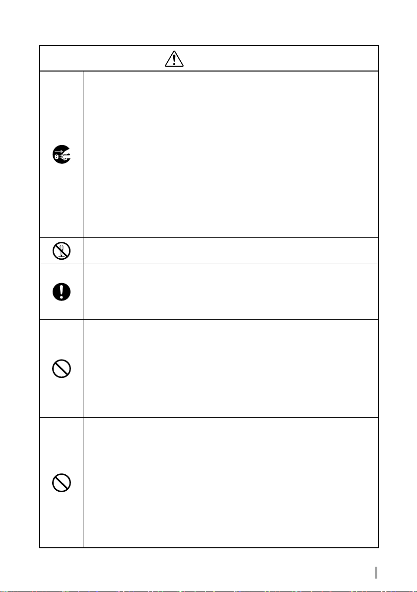
Meanings of pictorial symbols
Caution: Indicates directions that must be followed, and is used
to mark off a paragraph or illustration that provides detailed
instructions.
Prohibited: Indicates an action that is prohibited, and is used
to mark off a paragraph or illustration that provides detailed
instructions.
Mandatory: Indicates an action that must always be performed,
and is used to mark off a paragraph or illustration that provides
detailed instructions.
The use of this product inside a shower stall or bathtub could
result in re or electrical shock and cause serious damage. Refer
to the illustration for detailed instructions on prohibited actions.
Touching this product could result in fire or electrical shock
and cause serious damage. Refer to the illustration for detailed
instructions on prohibited actions.
Dissaembling this product could result in electrical shock or other
cause of personal injury. Refer to the illustration for detailed
instructions on prohibited actions.
Indicates that the user should unplug the AC adapter from the
wall socket or the USB cable from the computer. Refer to the
illustration for detailed instructions.
2
AV mixer A-PRO-4 Start Up Manual
Page 3
Precautions
Warning
■ In the event that any of the following were to occur, immediately unplug the
power cord from the wall socket and the USB cable from the computer.
In the event that the device emits smoke, a strange odor, or a strange sound:
Continued use of the device under these conditions could result in fire or electrical
shock. Please contact us to arrange for repairs, once the device no longer emits
smoke, strange odors, or sounds. Never attempt to repair the unit yourself. To do so is
dangerous.
In the event that water or other liquid seeps into the device:
Please contact us immediately. Using the device as it is could result in fire or electrical
shock.
In the event that foreign objects enter the device:
Please contact us immediately. Using the device as it is could result in fire or electrical
shock. (In particular, be careful when this device is used near children.)
In the event that an abnormality, a malfunction, or a failure is found in the device, its AC
adapter, or its electrical power cord:
Please contact us to arrange for repairs. Using the device as it is could result in fire or
electrical shock.
■ Do not disassemble or modify the machine.
Doing so might lead to a fire and/or electric shock.
■ Always use the AC adapter that came with the device.
Doing so might lead to a fire and/or electric shock.
■ Always use an electrical power cord and plug that are suitable for the area or
region where the device is being used.
Doing so might lead to a fire and/or electric shock.
■ Do not place heavy objects on top of the plug-in AC adapter, and be sure that
the device does not sit atop the electrical power cord.
Damage to the electrical power cord might lead to a fire and/or electric shock. If a carpet
or rug is spread over the cord, a heavy object might inadvertently be placed on it.
■ Do not damage, rework, apply heat, or apply excessive force in bending,
twisting, or pulling the plug-in AC adapter.
Damage to the electrical power cord could result in fire or electrical shock.
■ Do not connect many devices to a single power outlet.
Failure to do so might lead to fire.
■ Do not use the device in any of the following locations:
Places where the cause of fires, electrical shock, malfunction, discoloration, or
deformation is present.
• Places where the temperature is extremely high due to causes such as being subject
to direct sunlight or being in close proximity to a space heater or other device that
emits heat.
• Baths, sinks, wet floors, and other places with considerable moisture or high humidity.
• Places subject to steam or smoke.
• Places subject to salt corrosion.
• Places exposed to rainfall.
• Places where dust and sand accumulate easily.
• Places subject to constant vibration or movement.
• Tables, benches, or other places that are off-level, wobbly, or otherwise unstable.
AV mixer A-PRO-4 Start Up Manual
3
Page 4
Precautions
Warning
■ Do not place this device anywhere that water or foreign objects can penetrate it
or in a container that contains any kind of fluid.
Doing so might lead to a fire and/or electric shock.
■ Do not subject the device to strong impact.
To do so could result in damage or deformation of the device itself, in the device
rupturing, or in the emission of fluid, heat, smoke, or flame.
Caution
■ If the unit is not to be used for a long period of time, unplug the plug-in AC
adapter from the wall socket and the USB cable from the computer.
Failure to do so might lead to fire.
■ Be sure the electrical power cord is plugged securely into a wall socket.
Failure to do so could result in excessive heat or cause a fire if dust were to accumulate.
■ Connect and layout the cables properly.
Tripping on the cables or otherwise causing the device to fall over or fall to the floor could
result in personal injury.
■ When unplugging the plug-in AC adapter, do not pull on the electrical power
cord.
To do so could damage the electrical power cord and result in fire or electrical shock.
Always grasp the plug-in AC adapter itself to unplug it.
■ Keep the plug-in AC adapter away from hot objects.
The electrical power cord insulation might be melted, possibly resulting in a fire and/or
electric shock.
■ Never attempt to unplug the plug-in AC adapter with wet hands.
Doing so might lead to an electric shock.
■ Never use a wall socket that does not support the electric power plug securely
even when fully inserted.
To do so could cause heat and result in fire or electrical shock. In such a case, please
request that the retailer or an electrician replace the wall socket.
■ Remove all connections before moving the device.
Moving the device while external cables are connected could damage the electrical
power cord and result in fire or electrical shock.
■ Do not place your weight or heavy objects on the device.
In particular, be careful when using this device near children. Falling over or breaking
could result in personal injury.
■ Take care to avoid burns.
This device emits high heat, so take care to avoid burns.
4
AV mixer A-PRO-4 Start Up Manual
Page 5

Precautions
Precautions for Use
■ Power supply
• Never connect A-PRO-4 to any electrical outlet that is used to power inverter-controlled devices
or devices with an electric motor, such as refrigerators, washing machines, microwave ovens, or
air conditioners. The use of other electrical devices in close proximity to A-PRO-4 could result in
misoperation due to power noise or the generation of other electrical noise. In places where it would
be difficult to provide the A-PRO-4 with an exclusive power outlet, please use an electrical power noise
filter.
• The AC adapter will generate heat when used for long periods of time, but this is normal and does not
indicate a malfunction.
• To prevent misoperation or malfunction, be sure that all power is turned off when connecting A-PRO-4 to
other equipment.
■ Installation
• The installation of A-PRO-4 in close proximity to power amplifiers or other equipment with a large
transformer could induce hum. If this happens, increase the separation between the devices or change
their orientation to each other.
• The use of A-PRO-4 in close proximity to televisions or radios could interfere with the reception of audio
or video signals. If this happens, increase the separation between the devices.
• The use of A-PRO-4 in close proximity to mobile phones or other wireless devices could result in noise
or loss of image. If this happens, increase the separation between the devices or turn off the wireless
devices.
• Whenever A-PRO-4 are moved to a location where the ambient temperature differs to an extreme
degree, moisture (condensation) could form inside. Using an A-PRO-4 in this condition could result in
malfunctions. In which case, it is best to wait several hours for the condensation to evaporate before
use.
■ Maintenance
• Ordinarily, you should keep an A-PRO-4 clean by wiping it down with a soft, dry cloth or a tightly wrung
damp one. If the A-PRO-4 is heavily soiled, wipe it clean with a cloth dampened in a mild detergent and
then wipe it down with a soft, dry cloth.
• Never use benzene, paint thinner, or alcohol-based solvents to clean A-PRO-4. Doing so could result in
discoloration or deformation.
■ Repair
• We cannot warranty the performance of any device or AC adapter that has been disassembled or
modified by the user. Also, we reserve the right to refuse to repair devices or AC adapters.
• When repairing any device, the data stored in memory is sometimes lost. Be sure to back up your data
prior to repair. Please understand that we can neither restore nor provide compensation for lost data.
• We retain an inventory of the functional parts needed to repair A-PRO-4 for a period of six years after
discontinuation of manufacture. Repairs for A-PRO-4 are available only while repair parts are available.
Please feel free to inquire about repairs, however, even after this period is past, since some repairs are
still possible, depending upon the nature of the malfunction.
■ Other precautions
• Data stored in an A-PRO-4 memory could be lost due to malfunction or misoperation. Be sure to back
up your data prior to using an A-PRO-4. Please understand that we can neither restore nor provide
compensation for lost data.
• Never apply excessive force to the input and output connectors. To do so could result in malfunctions.
• Always adjust the volume settings so that you do not disturb people who are nearby.
• When transporting an A-PRO-4, wrap it in packing material and place it in its box or otherwise provide
equivalent protection.
• If you do dispose of the box and packing that came with the A-PRO-4, be sure to follow all local
regulations pertaining to the sorting of waste materials.
• Do not use this device to create video images that could adversely affect human health. Image switching
at extremely high speeds could cause headaches, nausea, or seizures in persons already susceptible to
illness. We cannot be held responsible for the effects of video images created with this device.
■ Intellectual property rights
• The names of products and companies shown in this manual are the trademarks or registered
trademarks of their respective owners.
• Never use A-PRO-4 for any application that violates the copyrights of a third party. We cannot be held
responsible for instances in which A-PRO-4 are used to violate the copyrights of a third party.
AV mixer A-PRO-4 Start Up Manual
5
Page 6

■Table of Contents
Introduction ---------------------------------------------- 7
1
Overview --------------------------------------------------------- 7
Checking the contents of the package ------------------ 7
Functionality and specifications ----------------- 8
2
Block Diagram -------------------------------------------------- 8
Program (PGM) output and preview (PVW) output --- 9
Product specifications ---------------------------------------- 9
Connection specifications ----------------------------------10
Names and functions of parts -------------------- 13
3
External View --------------------------------------------------13
Names and functions of top panel parts ----------------14
Names and functions of rear panel parts ---------------15
Onscreen menu names and functions of parts --------16
Connecting external devices ---------------------17
4
Connecting to a video input connector ------------------17
Connecting to a video output connector ----------------18
Connecting to an audio/GPI input/output connector
Other connections --------------------------------------------20
----19
5
6
7
8
6
AV mixer A-PRO-4 Start Up Manual
Basic operation ----------------------------------------21
Turning the power on and off. ----------------------------21
Change or verify the System Format --------------------22
Video and audio operation ------------------------23
Switching video ------------------------------------------------23
Switching audio -----------------------------------------------28
Troubleshooting --------------------------------------29
Support --------------------------------------------------- 31
Page 7
1
Introduction
Overview
• The A-PRO-4 is a video mixer that is capable seamlessly switching four separate video signals.
• It is also capable of switching and mixing audio embedded in video.
• It is equipped with input for two SDI channels and two HDMI channels, and one of the HDMI channels is
capable of being switched to analog video signal input.
• HDMI 1 has built-in scaler functionality and is capable of receiving input at resolutions that dier from other
input/output.
• It is equipped with input and output connectors for external audio and is capable of mixing audio from an
external source or outputting mixed audio to other devices.
• It is equipped with USB audio video output connectors and can be connected to a PC for live streaming,
teleconferences, or other similar uses.
• It is equipped with a REF IN connector and capable of operation with a GENLOCK system.
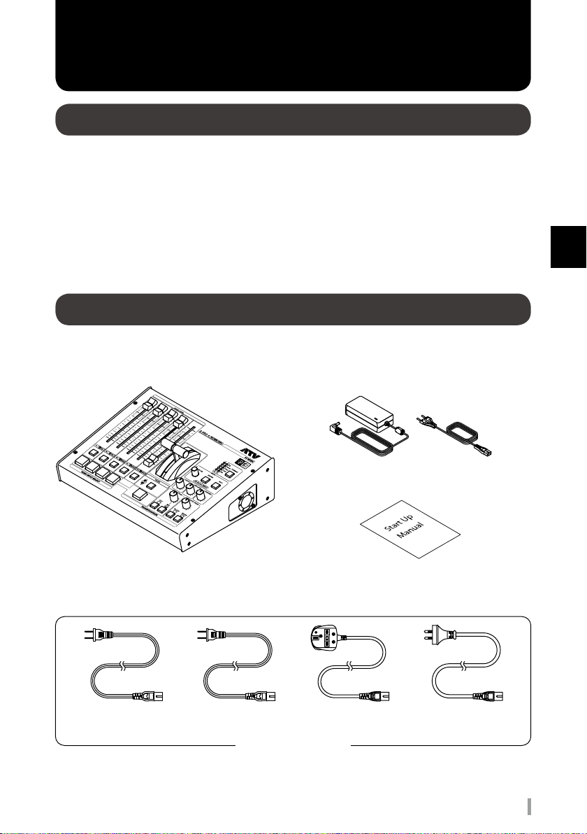
Checking the contents of the package
The following content is packaged with this product.
Please contact a retail seller should you find that any of the following items are not included with your
purchase.
AC adapter and EU two-prong electrical power cord
1
Introduction
PSE
for Japan
A-PRO-4
US
for North America
Electrical power cords x 4
Start Up Manual (this document)
UK(BSI 3A)
for UK
AV mixer A-PRO-4 Start Up Manual
AU(SAA 2pin)
for Australia
7
Page 8
2
Caution
Functionality and specifications
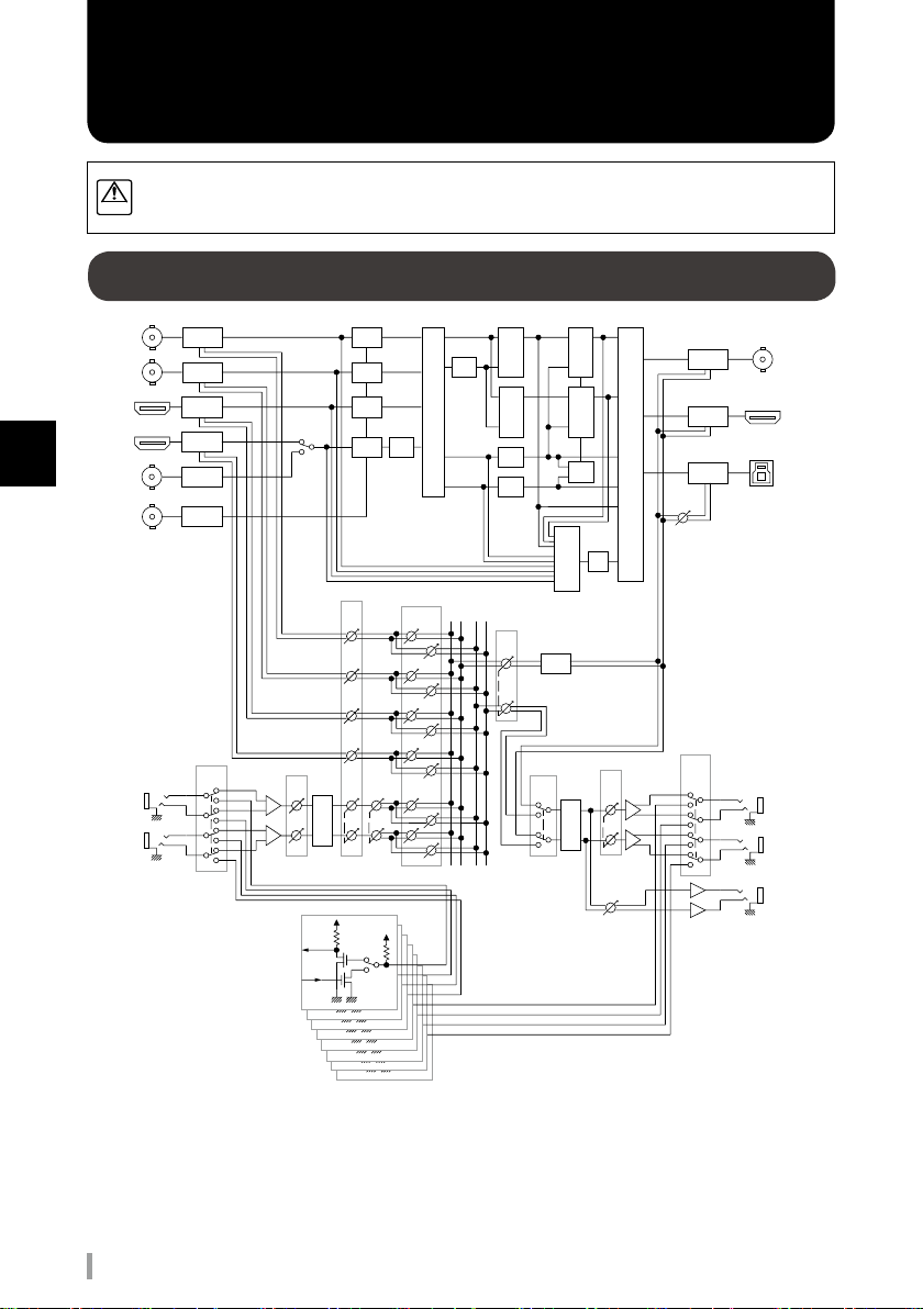
In the interest of product improvement, the specifications and/or appearance of this unit are
subject to change without prior notice.
Block Diagram
IN 1 SDI
IN 2 SDI
IN 3 HDMI
2
Functionality and specifications
IN 4 HDMI
IN 4 VIDEO
REF IN
GPI/AUDIO IN
L
R
Audio
De-embed
Audio
De-embed
Audio
De-embed
Audio
De-embed
Video
Decoder
Genlock
Audio In
Mode
FS
FS
MONO/
STEREO
GPI 1
+5V
GPI 2
+5V
GPI 3
Scaler
+5V
GPI 4
+5V
GPI 5
+5V
GPI 6
4x4
Matrix
Sw
Audio
Follow
+5V
+5V
+5V
GPI 7
GPI 8
FS
FS
Ch
Level
Input
Gain
A/D
Connect
to CPU
Connect
to CPU
Connect
to CPU
Connect
to CPU
Connect
to CPU
Connect
to CPU
Connect
to CPU
Connect
to CPU
PGM
Mix/
Wipe
Scaler
PVW
Mix/
Wipe
AUX1
AUX2
PGM
PVW
BUS
BUS
Out
Level
PGM
DSK
PVW
DSK
6x3
Matrix
Sw
Alpha
Gen
Multi
OSD
View
Audio
Delay
MON
SEL
Max
Out
Level
D/A
PHONES
Level
USB
Level
Audio
Out
Mode
Audio
Embed
Audio
Embed
Audio
Embed
SDI OUT
HDMI OUT
USB3.0 OUT
GPI/AUDIO OUT
L
R
PHONES
8
AV mixer A-PRO-4 Start Up Manual
Page 9
Functionality and specifications
Program (PGM) output and preview (PVW) output
Program (PGM) output
• The red VIDEO INPUT SELECT button outputs an input signal.
• PGM output default settings are SDI and USB output.
• No onscreen menu is displayed.
Preview (PVW) output
• In Direct mode, the red VIDEO INPUT SELECT button outputs an input signal.
( Refer to P.23 Toggling switching modes)
• In Preview mode, the green Video Input Select button outputs an input signal.
( Refer to P.23 Toggling switching modes)
• MultiView output default setting is HDMI output. (Multiview displays on one screen PGM and PVW outputs)
• Onscreen menu is displayed only MultiVIew output.
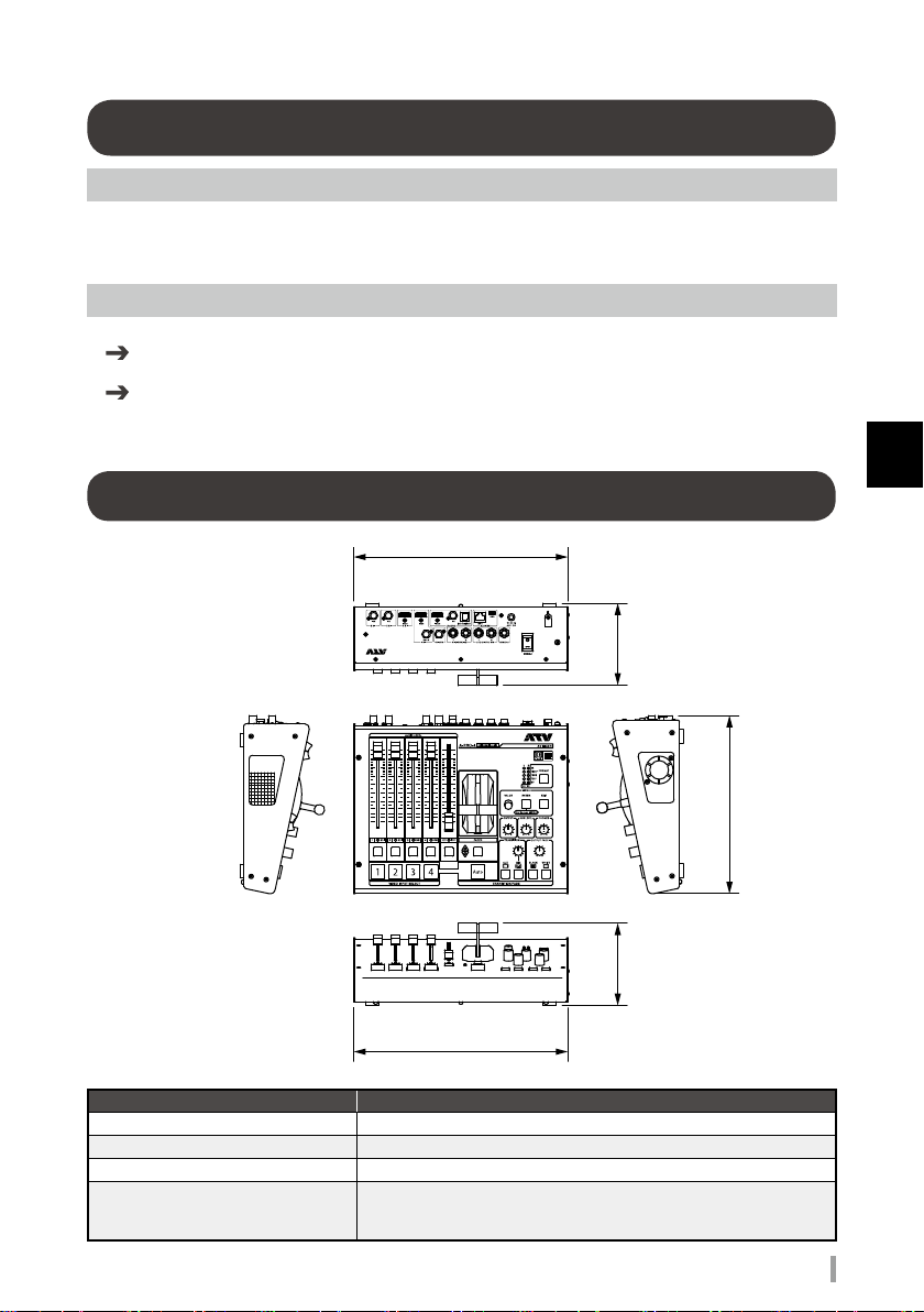
Product specifications
307
(12-1/8W)
119119
(4-11/16)(4-11/16)
2
Functionality and specifications
246
(9-11/16)
307
(12-1/8)
Item Description
Dimmensions
Weight 2.9 kg 6 lbs 7 oz (without AC adaptor & Electrical power cord)
Operation Temparature +0 to +40 degrees Celsius +41 to +104 degrees Fahrenheit
Accessories
307(W) x 246(D) x 119(H) [mm] 12-1/8(W) x 9-11/16(D) x 4-11/16(H) [inch]
AC adaptor
Electrical power cords x 5
Startup Manual
AV mixer A-PRO-4 Start Up Manual
9
Page 10
Functionality and specifications
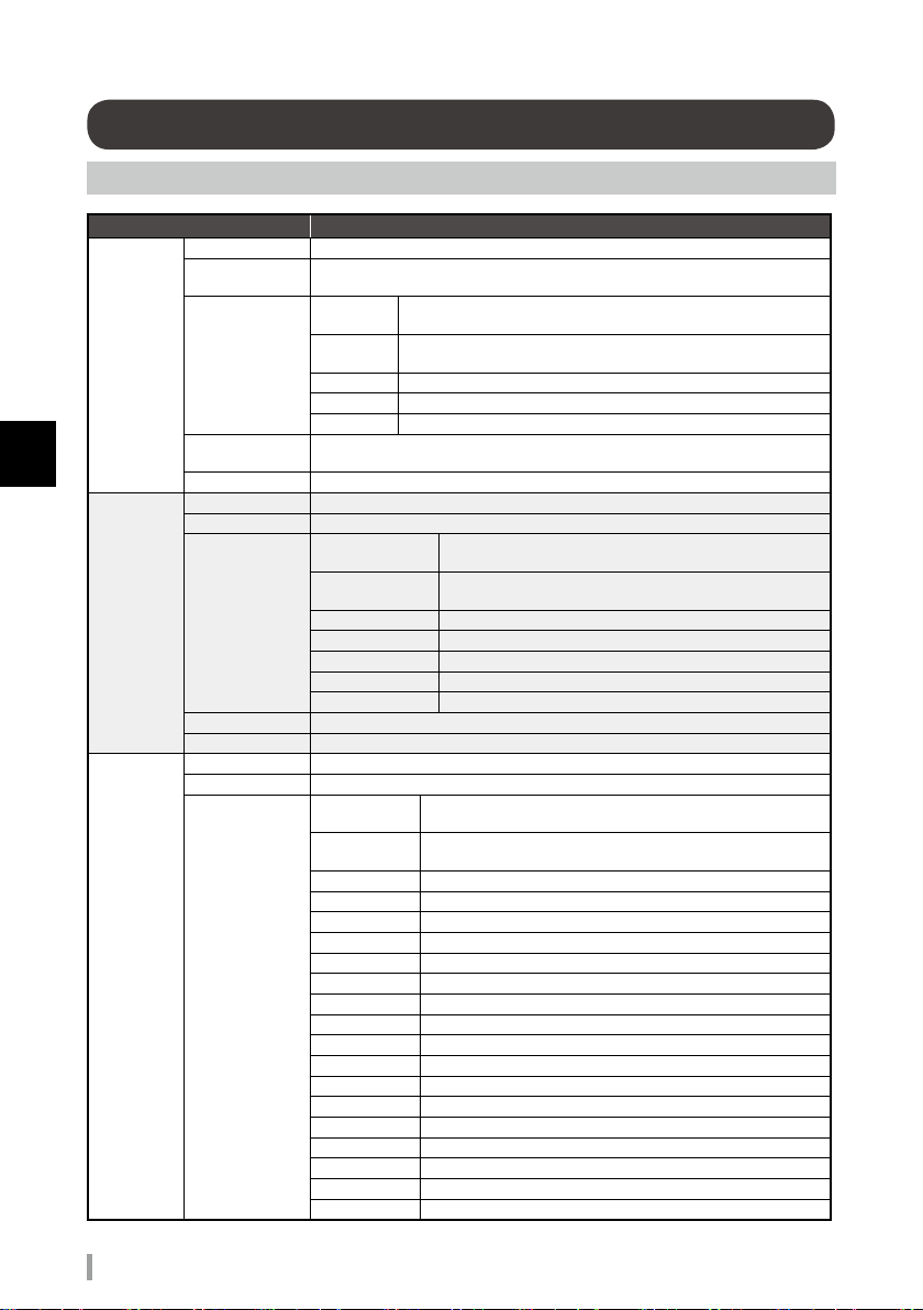
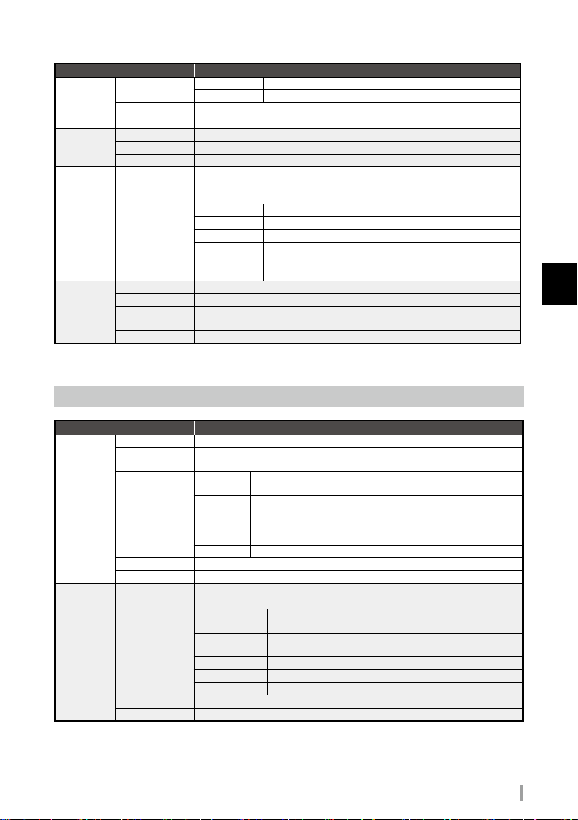
Connection specifications
Input Connectors
SDI IN
2
Functionality and specifications
HDMI IN
(IN3)
HDMI IN
(IN4)
Item Description
Connector BNC type x 2
Signal Standards
Video Format
Color Format
Audio Format
Connector Type A (19 pins) x 1
Signal Standards HDMI1.4
Video Format
Color Format 10/12 bits YCC4:2:2, 8/10/12 bits YCC/RGB4:4:4
Audio Format Linear PCM, 16 to 24 bits, 32 to 48 kHz, 2 to 8 ch
Connector Type A (19 pins) x 1
Signal Standards HDMI1.4
Video Format
SMPTE ST2081 SMPTE ST424 (SMPTE ST425-AB) SMPTE ST292 SMPTE
ST259-C
2048x1080
1920x1080
1280x720
720x480 59.94i (Conforms to ITU-R BT.656-3/5)
720x576
10 bits YCC4:2:2, 12 bits YCC/RGB4:4:4, 10 bits RGBA/YCCA4:4:4:4,
12 bits YCCA4:2:2:4
Linear PCM, 24/20 bits, 48 kHz, 16 ch (Conforms to SMPTE ST299, ST272-C)
2048x1080
1920x1080
1280x720 60p/59.94p/50p (Conforms to CEA-861-F)
720x480 59.94p (Conforms to CEA-861-F)
720x576 50p (Conforms to CEA-861-F)
720(1440)x480 59.94i (Conforms to CEA-861-F)
720(1440)x576 50i (Conforms to CEA-861-F)
2048x1080
1920x1080
1280x720 60p/59.94p/50p (Conforms to CEA-861-F)
720x480 59.94p (Conforms to CEA-861-F)
720x576 50p (Conforms to CEA-861-F)
720(1440)x480
720(1440)x576
640x480 60/72/75/85 (Conforms to VESA DMT)
800x600 56/60/72/75/85 (Conforms to VESA DMT)
1024x768 60/70/75/85 (Conforms to VESA DMT)
1152x864 75 (Conforms to VESA DMT)
1280x768 60/75/85 (Conforms to VESA DMT)
1280x800 60/75/85 (Conforms to VESA DMT)
1280x960 60/85 (Conforms to VESA DMT)
1280x1024 60/75/85 (Conforms to VESA DMT)
1360x768 60 (Conforms to VESA DMT)
1400x1050 60/75 (Conforms to VESA DMT)
1440x900 60/75/85 (Conforms to VESA DMT)
1600x1200 60 (Conforms to VESA DMT)
60p/59.94p/50p/48p/47.95p/30p/29.97p/25p/24p/23.98p/30PsF/
29.97PsF/25PsF/24PsF/23.98PsF (Conforms to SMPTE ST2048)
60p/59.94p/50p/30p/29.97p/25p/24p/23.98p/60i/59.94i/50i/30PsF/
29.97PsF/25PsF/24PsF/23.98PsF (Conforms to SMPTE ST274)
60p/59.94p/50p/30p/29.97p/25p/24p/23.98p (Conforms to SMPTE ST296)
50i (Conforms to ITU-R BT.656-3/5)
60p/59.94p/50p/48p/47.95p/30p/29.97p/25p/24p/23.98p
(SMPTE ST2048 Timings)
60p/59.94p/50p/60i/59.94i/50i/30p/29.97p/25p/24p/23.98p
(Conforms to CEA-861-F)
60p/59.94p/50p/48p/47.95p/30p/29.97p/25p/24p/23.98p
(SMPTE ST2048 Timings)
60p/59.94p/50p/60i/59.94i/50i/30p/29.97p/25p/24p/23.98p
(Conforms to CEA-861-F)
59.94i (Conforms to CEA-861-F)
50i (Conforms to CEA-861-F)
10
AV mixer A-PRO-4 Start Up Manual
Page 11
Functionality and specifications
Item Description
HDMI IN
(IN4)
VIDEO IN
REF IN
AUDIO IN
Video Format
Color Format 10/12 bits YCC4:2:2, 8/10/12 bits YCC/RGB4:4:4
Audio Format Linear PCM, 16 to 24 bits, 32 to 48 kHz, 2 to 8 ch
Connector BNC type x 1
Signal Standards ITU-R BT.470-6
Video Format NTSC, NTSC-J, PAL
Connector BNC type x 1
Signal Standards
Signal Format
Connector 1/4" TRS phone type (balanced) x 2
Input Level -50 to +4 dBu
Maximum Input
Level
Impedance 150 k / 600 ohms selectable
*0dBu=0.775Vrms
Output Connectors
Item Description
Connector BNC type x 1
Signal Standards
SDI OUT
HDMI OUT
Video Format
Color Format 10 bits YCC4:2:2, 10 bits YCC/RGB4:4:4
Audio Format Linear PCM, 24/20 bits, 48 kHz, 2 ch (Conforms to SMPTE ST299, ST272-C)
Connector Type A (19 pins) x 1
Signal Standards HDMI1.4
Video Format
Color Format 10 bits YCC4:2:2, 8/10 bits YCC/RGB4:4:4
Audio Format Linear PCM, 24 bits, 48 kHz, 2 ch
1680x1050 60 (Conforms to VESA DMT)
1920x1200 60 Reduced Blanking (Conforms to VESA DMT)
B.B. (SMPTE ST318), Bi-Level (ITU-R BT.1358-1), HD Tri-Level (SMPTE
ST274, ST296)
1920x1080 59.94p/50p/59.94i/50i (Conforms to SMPTE ST274)
1280x720 59.94p/50p (Conforms to SMPTE ST296)
720x480 59.94p (Conforms to ITU-R BT.1358-1)
720x576 50p (Conforms to ITU-R BT.1358-1)
720x480 59.94i (Conforms to SMPTE ST318)
720x576 50i (Conforms to SMPTE ST318)
+24 dBu
SMPTE ST2081 SMPTE ST424 (SMPTE ST425-AB) SMPTE ST292 SMPTE
ST259-C
2048x1080
1920x1080
1280x720 59.94p/50p (Conforms to SMPTE ST296)
720x480 59.94i (Conforms to ITU-R BT.656-5)
720x576 50i (Conforms to ITU-R BT.656-5)
2048x1080
1920x1080
1280x720 59.94p/50p (Conforms to CEA-861-F)
720(1440)x480 59.94p/59.94i (Conforms to CEA-861-F)
720(1440)x576 50p/50i (Conforms to CEA-861-F)
59.94p/50p/29.97p/25p/24p/23.98p (Conforms to SMPTE
ST2048)
59.94p/50p/29.97p/25p/24p/23.98p/59.94i/50i (Conforms to
SMPTE ST274)
59.94p/50p/29.97p/25p/24p/23.98p (SMPTE ST2048
Timings)
59.94p/50p/29.97p/25p/24p/23.98p/59.94i/50i (Conforms to
CEA-861-F)
2
Functionality and specifications
AV mixer A-PRO-4 Start Up Manual
11
Page 12

Functionality and specifications
USB3.0
OUT
AUDIO OUT
2
Functionality and specifications
PHONES
OUT
*0dBu=0.775Vrms
Other Connectors
USB2.0
LAN
DC IN
Item Description
Connector USB Type B (Super Speed USB) x 1
Standards
Video Format
(SS)
Video Format
(HS)
Color Format 8 bits YCC4:2:2
Audio Format Linear PCM, 16 bits, 48 kHz, 2 ch
Connector 1/4" TRS phone type (balanced) x 2
Output Level -20 to +4 dBu
Maximum Output
Level
Minimun Load
Impedance
Connector 1/4" TRS phone type (stereo) x 1
Item Description
Connector Micro USB Type B (Hi-Speed USB) x 1
Standards USB 2.0 High Speed (HS)
Connector RJ45
Standards 10/100Base-T
Power Voltage 12 to 20 V
Power Consumption 35 W
USB 3.0 Super Speed (SS) / USB 2.0 High Speed (HS)
USB Video Class 1.1, USB Audio Class 1.0
2048x1080 59.94p/50p/29.97p/25p/24p/23.98p
1920x1080 59.94p/50p/29.97p/25p/24p/23.98p/59.94i/50i
1280x720 59.94p/50p
720x480 59.94p/59.94i
720x576 50p/50i
720x480 59.94i
720x576 50i
+24 dBu
20k ohms
Processing
Video Processing 10 bits YCC4:4:4
Audio Processing 24 bits 48 kHz
12
AV mixer A-PRO-4 Start Up Manual
Item Description
Page 13

3
Caution
Names and functions of parts
External View
Top panel
Refer to P.14
Vents
Rear panel
Refer to P.15
3
Names and functions of parts
Vents
Do not block the vents.
AV mixer A-PRO-4 Start Up Manual
13
Page 14

Names and functions of parts
Names and functions of top panel parts
VIDEO fader
Switch video.
Refer to P.26 Use the VIDEO fader.
EXT INPUT indicator
Displays audio level input from AUDIO
IN connector.
Green: -48 dBFS or higher
Red: -6 dBFS or higher
Off: No input
AUDIO LEVEL fader
Adjust volume for each channel.
Refer to P.28 Adjust the audio volume.
3
Names and functions of parts
1 2 3 4
Auto
Level meter / format indicator
Displays audio output level.
Press the FORMAT button to light the
current System Format indicator.
FORMAT button
Change or verify the System Format.
Refer to P.22 Change or verify the
System Format
QR code
Read this QR code into
your smartphone or other
device to access our
product support website.
MENU
Operate the onscreen menu.
Refer to P.16 Onscreen menu
names and functions of parts
OUTPUT LEVEL knob
Adjust audio output level.
Refer to P.28 Adjust the audio volume.
USB LEVEL knob
Adjust USB audio output level.
Refer to P.28 Adjust the audio volume.
PHONES knob
Adjust headphone output level.
Refer to P.28 Adjust the audio volume.
Input indicator
Displays input status for each channel.
Green: normal input
Off: No input
VIDEO INPUT SELECT button
Switch video input.
Refer to P.23 Switching video
AUDIO INPUT SELECT button
Switch audio follow.
Refer to P.28 Synchronize the audio to the video
and switch. (Audio follow function)
FADER indicator
Displays switching direction for video fader.
Refer to P.26 Use the VIDEO fader.
FADER button
Toggle switching modes.
Refer to P.23 Toggling switching modes
14
AV mixer A-PRO-4 Start Up Manual
OUTPUT FADE knob
Adjust time needed for video fade out/fade in.
OUTPUT FADE button
Fade in or fade out the video.
BLACK: Fade to black.
WHITE: Fade to white.
Refer to P.27 Fade in or fade out the output video.
TRANSITION knob
Adjust time needed for switching video.
TRANSITION button
Select video switching effect.
CUT: Video switches instantly.
MIX: Current video fades out as next video fades in.
Refer to P.23 Switch video using the dissolve effect.
Refer to P.25 Switch video using the cut effect.
Auto button
Switch videos in TRANSITION settings.
Refer to P.23 Switch video using the dissolve effect.
Refer to P.25 Switch video using the cut effect.
Page 15

Names and functions of parts
Names and functions of rear panel parts
GPI/AUDIO OUT connector
Output analog audio signal.
Can be used as GPI connector.
Refer to P.19 Connecting to an audio/GPI
input/output connector
PHONES connector
Connect headphones.
Power switch
Switch electrical power on or off.
Refer to P.21 Turning the
power on and off.
Function ground
terminal
Connect to ground.
Cord holder
(Used to hold electrical power cord.)
DC IN connector
Connect the AC adapter.
REMOTE USB connector
Connect to the PC.
Refer to P.20 Other connections
REMOTE LAN connector
Connect to the network.
Refer to P.20 Other connections
GPI/AUDIO IN connector
Input analog audio signal.
Can be used as GPI connector.
Refer to P.19 Connecting to an audio/
GPI input/output connector
REF IN connector
Input a reference signal for frame
synchronization.
Refer to P.20 Other connections
VIDEO IN connector
Input a composite video signal.
Refer to P.17 Connecting to a video
input connector
SDI IN connector
Input 6G/3G/HD/SD-SDI signals.
Refer to P.17 Connecting to
a video input connector
HDMI IN connector
Input an HDMI signal.
Refer to P.17 Connecting to
a video input connector
HDMI OUT connector
Output an HDMI signal.
(Default setting: MultiView output)
Refer to P.18 Connecting to a video output connector
SDI OUT connector
Output 6G/3G/HD/SD-SDI signals.
(Default setting: PGM output)
Refer to P.18 Connecting to a video output connector
USB (UVC+UAC) connector
Output USB video and USB audio signals.
(Default setting: PGM output)
Refer to P.20 Other connections
3
Names and functions of parts
AV mixer A-PRO-4 Start Up Manual
15
Page 16

Names and functions of parts
Onscreen menu names and functions of parts
Output video: PVW output
MENU
Input ENTER
Input
Ext Audio Input ENTER
Output ENTER
Ext Audio Output ENTER
System ENTER
Parameter name
Display parameter groups and parameter names.
3
The selected item is highlighted.
Names and functions of parts
Top Panel
Parameter value
Display the parameter value.
ENTER: Press the Enter button to display menu for
that group.
RESET: Press the Enter button to reset the parameter
values for that group to default.
Operating the onscreen menu
MENU EXIT button
When at the top of the hierarchy: Hide the onscreen menu.
When a parameter name is selected: Move up one level.
When a parameter value is selected: Cancel editing.
MENU ENTER button
When the onscreen menu is hidden: Display the onscreen menu.
When a parameter name is selected: Edit the parameter value.
When a parameter group is selected: Move down one level.
When a parameter value is selected: Store the current value.
MENU VALUE button
When a parameter name is selected: Select an item.
When a parameter value is selected: Select the value.
16
AV mixer A-PRO-4 Start Up Manual
Page 17

4
Caution
Connecting external devices
Connecting to a video input connector
HDMI connectors on this device are not HDCP compliant.
VIDEO IN connector
Rear panel
Composite video signal
Standard definition video camera
Connection Name of connector Description
Connecting
SDI devices
Connecting
HDMI devices
Connecting
a composite
video device
and
video player
SDI IN connector
HDMI IN
connector
(IN 3)
HDMI IN
connector
(IN 4)
SDI IN connector
Consumer-use video cameras,
Connect to a professional-use video camera, video player, or other SDI
device.
Match the input format to the system format of this device.
Refer to P.22 Verify the System Format
Connect to a consumer-use video camera, PC, or other HDMI output device.
Match the input format to the system format of this device.
Refer to P.22 Verify the System Format
When connecting a plug-and-play device, the system format is automatically
specified by the device’s EDID information.
Connect to a consumer-use video camera, PC, or other HDMI output device.
Irrespective of the system format of this device, input is possible in the
format given the connection specifications.
Refer to P.10 Connection specifications
Connect to a standard definition video camera or video player.
When inputting a video signal, do not connect to HDMI connector IN 4. HDMI
connector IN 4 is prioritized.
For video devices with RCA connectors, use commercially available RCABNC conversion.
HDMI SDI
PCs, etc.
HDMI IN connector (IN 4)
HDMI IN connector (IN 3)
SDI IN connector
4
Connecting external devices
Professional-use video cameras,
video players, etc.
AV mixer A-PRO-4 Start Up Manual
17
Page 18

Connecting external devices
Connecting to a video output connector
SDI OUT connector
USB (UVC+UAC) connector
Rear panel
HDMI OUT connector
4
Connecting external devices
Connection Name of connector Description
Connecting
SDI devices
Connecting
HDMI devices
USB
(UVC+UAC)
connector
connection
USB
PC
SDI OUT
connector
HDMI OUT
connector
USB(UVC+UAC)
connector
SDI
Professional-use video display,
video recorder, etc.
Connect to a professional-use video display, video recorder, or other SDI
device. Use a device that is compliant with the system format of this device.
Refer to P.22 Verify the System Format
Connect to a consumer-use video display, TV, or other HDMI output
connector.
Use a device that is compliant with the system format of this device.
*This device is not Plug-and-Play compliant.
This device can be connected to a USB 3.0 connector to output audio and
video to a PC. It will be automatically detected as a USB camera and USB
audio device and will operate on standard drivers for both Windows and Mac
OS X operating systems, making it useful for a wide variety of applications.
* We recommend specifying a 1080p or 720p system format when using a
USB (UVC+UAC) connector.
Consumer-use video display,
HDMI
TV, etc.
18
AV mixer A-PRO-4 Start Up Manual
Page 19

Connecting external devices
Caution
Connecting to an audio/GPI input/output connector
In order to protect speakers and other devices from damage when connecting audio devices, turn
down the volume for all devices and turn o the electrical power before connecting.
GPI/AUDIO IN connectorGPI/AUDIO OUT connector
Rear panel
Balanced input/output or GPI input/output
Audio device or GPI device
Connection Name of connector Description
GPI/AUDIO OUT
Connecting
audio devices
Connecting GPI
devices
connetor
GPI/AUDIO IN
connetor
GPI/AUDIO OUT
connetor
GPI/AUDIO IN
connetor
This device features TRS-balanced I/O connectors.
Use a cable suitable for the device to be connected.
Default signal levels are +4dBu, which can be adjusted to match the
device to be connected.
See the reference manual for details on how to adjust this device.
GPI/AUDIO connectors can be used as GPI terminals based on internal
parameter settings. Also, GPI can be toggled between input and output.
See the reference manual for details on how to use this device.
4
Connecting external devices
AV mixer A-PRO-4 Start Up Manual
19
Page 20

Connecting external devices
Other connections
REMOTE LAN connector
REMOTE USB connector
Rear panel
REF IN connector
4
Connecting external devices
Connection Name of connector Description
Connecting
to REF IN
connectors
Connecting to
REMOTE LAN
connectors
Connecting to
REMOTE USB
connectors
USB
PC
REF IN connector
REMOTE LAN
connector
REMOTE USB
connector
LAN
Networks
This device is capable of operation with a GENLOCK system when a
synchronization signal is input. Input is possible for synchronization signals
described in the connection specifications. Input a reference signal with a
frame rate identical to that of the system format of this device.
Refer to P.10 Connection specifications
Refer to P.22 Verify the System Format
Connecting to a network will enable the user to control a wide range of this
device’s functionality from a browser.
See the reference manual for details on how to use this device.
Connecting the remote USB connector of this device to the USB 2.0 port of a
PC will enable the user to change parameter values and update software.
See the reference manual for details on how to use this device.
Synchronization signals
Device to be connected
20
AV mixer A-PRO-4 Start Up Manual
Page 21

5
Caution
Caution
Warning
Basic operation
Turning the power on and off.
Always use an electrical power cord that is suitable for the area or region where the device is being used.
Be sure to use only the electrical power cord and AC adapter that came with this device.
Turning on the power.
This device does require a brief amount
of time to boot up after turning on the
electrical power.
Connect the electrical power cord to
1
the AC adapter.
Connect the output connector of the
2
AC adapter to the DC IN connector
of this device.
Connect the electrical power cord to
3
a wall outlet.
Turn the power switch on (to the I
4
position).
Turning off the power.
Hide the onscreen menu before turning
off the power. The power is turned off
while the onscreen menu is displayed,
any changes made to parameter values
will not be saved.
Wall outlet
Electrical power
Power switch
Rear panel
DC IN connector
Output connector
of the AC adapter
3
cord
Power switch
Rear panel
DC IN connector
4
2
1
1
3
Turn the power switch off (to the O
1
position).
Remove the electrical power cord
2
from the wall outlet.
Wall outlet
2
AC adapter
Output connector
of the AC adapter
AC adapter
5
Basic operation
Remove the output connector of
3
the AC adapter from the DC IN
connector of this device.
Electrical power
cord
AV mixer A-PRO-4 Start Up Manual
1
21
Page 22

Basic operation
Change or verify the System Format
Verify the System Format
Press the FORMAT button.
1
5
Basic operation
The level meter/format indicator comes
2
on. (The current system format)
Press the FORMAT button a second
3
time.
Return to the level meter indicator.
Change the System Format
Press the FORMAT button and hold
1
for one second.
The level meter/format indicator comes
2
on, and the format button flashes. (The
current system format)
Press the Format button and select
3
the desired System Format.
Each time the button is pressed, a
different indicator comes on.
Press the MENU ENTER button.
4
Finalize the new system format.
To exit without finalizing, press the
MENU EXIT button.
Turn off the power and turn on the
5
power again.
Changing the system format needs
reboot the power.
2
2
4
Finalize
Power switch
Rear panel
1
3
1
3
Exit without
finalizing
5
22
AV mixer A-PRO-4 Start Up Manual
Page 23

6
Video and audio operation
Switching video
Toggling switching modes
There are two types of switching modes available: direct mode and preview mode.
Press the FADER button to toggle the switching mode.
Buttons to use
FADER
button
VIDEO INPUT SELECT
Auto
button
VIDEO fader Not available Switch video and audio manually.
Switching mode
/ Indicator Off On
Start switching PGM output video,
button
PVW output video, and audio.
Not available
Direct mode Preview mode
When the green light is on, switch the
PVW output video only.
Start switching PGM output video and
audio.
Switch video using the dissolve effect.
Press the MIX button.
1
The indicator change to orange and
the transition type change to MIX.
Specify a switching time using the
2
TRANSITION knob.
2
1
6
Video and audio operation
For direct mode
Example: For an original video [1] and an
3
4
alternate video [3]
Press the alternate video [3] button.
The output video slowly transitions
within the switching time specified with
the TRANSITION knob.
During the transition, the original video
[1] button and the alternate video [3]
button both flash red.
Once the transition is complete, the
alternate video [3] button stops flashing
and is a steady red.
Flashing red Flashing red
3
Output video
4
Steady red
AV mixer A-PRO-4 Start Up Manual
23
Page 24

Video and audio operation
For preview mode
Example: For an original video [1] and an
alternate video [3]
Steady green
Press the alternate video [3] button.
3
The indicator is steady green.
The PVW output video switches.
Press the Auto button.
4
The PGM output video slowly
transitions within the switching time
specified with the TRANSITION knob.
While at the same time, the PVW
output video slowly transitions to the
original video. During the transition,
the original video [1] button flashes
red and the alternate video [3] button
flashes green.
Once the transition is complete,
5
the original video [1] button stops
flashing and is a steady green, while
the alternate video [3] button stops
flashing and is a steady red.
6
Video and audio operation
Flashing red
5
3
Output video: PVW output
Flashing green
4
Output video: PGM output
Output video: PVW output
Steady red
Change video switching/mixing effect.
Press the MIX or CUT button
1
Each time you press and hold the button, the color of the button will change and the video
switching/mixing effect will change.
Orange : Dissolve
Green : Wipe
Red : Picture in picture
24
AV mixer A-PRO-4 Start Up Manual
and hold for one second.
Steady green
Page 25

Switch video using the cut effect.
Video and audio operation
Example: For an original video [1] and an
1
For direct mode
2
For preview mode
2
alternate video [3]
Press the Cut button.
The indicator comes on and the
transitions are cut.
Press the alternate video [3] button.
The output video switches.
The original video [1] button goes out
and the alternate video [3] button is
steady red.
Press the alternate video [3] button.
The PVW output video switches, and
the indicator is steady green.
Off
1
Steady red
2
Steady green
2
6
Video and audio operation
Press the Auto button.
3
The PGM output video switches.
The original video [1] button is steady
green and the alternate video [3]
button is steady red.
Steady red
3
Steady green
AV mixer A-PRO-4 Start Up Manual
25
Page 26

Video and audio operation
Use the VIDEO fader.
The VIDEO fader is available in preview mode. (
Example: For an original video [1] and an
1
alternate video [3]
Verify that the FADER button
indicator is on.
[If the indicator is not on]
Press the FADER button.
The indicator comes on.
Refer to P.23 Toggling switching modes)
1
Press the MIX button.
2
The indicator comes on and the
transitions are MIX or WIPE.
Press the alternate video [3] button.
3
The indicator is steady green.
The PVW output video switches.
Operate the VIDEO fader.
4
The PGM output video slowly
transitions per the position of the
VIDEO fader.
6
Video and audio operation
During the transition, the original video
[1] button flashes red and the alternate
video [3] button flashes green.
The switching direction can be verified
from the FADER indicator.
The original video [1] button is steady
5
green and the alternate video [3]
button is steady red. Switching is
complete.
Flashing red
Output video: PVW output
Output video: PGM output
4
FADER indicator
Steady red: PGM output
Steady green: PVW output
Flashing red
2
3
Flashing green
26
AV mixer A-PRO-4 Start Up Manual
Steady red
5
Steady green
Page 27

Fade in or fade out the output video.
Caution
For fade out
Video and audio operation
Specify the fade time with the
1
OUTPUT FADE knob.
Press the button to be set.
2
BLACK button: black video image
WHITE button: white video image
The output video slowly fades out to
the specified color within the specified
time.
During fade out, the specified button
indicator flashes red.
When the indicator stops flashing and
3
is steady red, the fade out is complete.
For fade in
Press the button with the lit
1
indicator.
The output video slowly fades in.
During fade in, the pressed button
indicator flashes red.
When the indicator goes out, the fade
2
out is complete.
1
2
3
1 1
2
2
Flashing red
Steady red
Steady red
6
Video and audio operation
Fade in or out effects PGM output only.
How to use OUTPUT FADE buttons for DSK.
The OUTPUT FADE button can also be used as a Down Stream Keyer (DSK).
For details, please refer to the reference manual.
Press the BLACK button
1
The indicator change to green and the PVW output change to key mixed signal.
Please adjust key parameters.
Press the WHITE button
2
The indicator change to red and the PGM output slowly change to key mixed signal.
.
.
AV mixer A-PRO-4 Start Up Manual
Off
27
Page 28

Video and audio operation
Switching audio
Synchronize the audio to the video and switch. (Audio follow function)
Press any of the AUDIO INPUT SELECT buttons to synchronize the audio to the video and switch.
Audio follow function AUDIO INPUT SELECT button
On
Off Steady orange
Other than the steady orange
indicators
Adjust the audio volume.
Adjust the audio volume for each video input.
Adjust the audio volume using the AUDIO LEVEL fader of each channel.
Adjust the audio volume for external audio input.
Adjust the audio volume using the AUDIO LEVEL fader.
Synchronize the audio to the video and switch.
Output the audio channel with the steady orange
indicator, irrespective of the video.
Adjust the overall audio volume.
Adjust the overall audio volume using the OUTPUT LEVEL
knob.
Turn the knob all the way to the right for unity gain (0dB).
Description
6
Video and audio operation
Audio output
AUDIO INPUT SELECT button
Steady red: Audio is being output.
Steady orange: Audio is being output.
Steady green: Audio is being output to PVW
Off: Audio is not being output.
28
AV mixer A-PRO-4 Start Up Manual
BUS.
Refer to P.8 Block Diagram
Adjust the audio volume to the headphones.
Adjust the headphone output audio volume using
the PHONES knob.
Adjust the USB output audio volume.
Adjust the USB audio output volume using the USB
LEVEL knob.
Turn the knob all the way to the right for unity gain (0dB).
Page 29
7
In many of the following cases, the problem is not due to a malfunction. Please double check before
requesting repairs to your device.
If you are unable to resolve the issue yourself, please visit the ATV website. ( Refer to P.31)
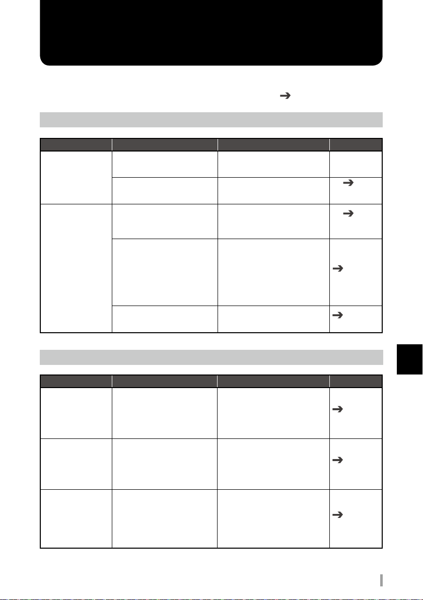
Troubleshooting
Video
What should you do if . . .
No HDMI input.
No SDI output video
is displayed.
Double check these items. Countermeasures Reference
Is the video signal being input
copyright protected?
Is the A-PRO-4 compliant with
the format being input?
Is the connected SDI device
compliant with 3G-SDI?
Have the 3G-SDI Out Type
settings been specified correctly.
Is the SDI Color set to RGB4:4:4
or YCC4:4:4?
Audio
What should you do if . . .
Analog audio input
volume is low.
Even after adjusting
the Input Gain, the
analog audio input is
distorted.
Analog audio output
volume is high.
Double check these items. Countermeasures Reference
Are the Input Impedance and
Input Gain settings correct?
Is the Input Impedance setting
correct?
Adjust the Maximum Output
Level.
A-PRO-4 are not compliant with
HDCP and does not accept input of
copyright-protected video signals.
Review the specifications and input
a format with which the A-PRO-4 is
compliant.
Either connect to a 3G-SDI-compliant
device or, if using an HD-SDIcompliant device, specify the System
Format as either 1080i or 720p.
Depending upon the connected
device, there are times when either
Level-A or Level-B can be used but
not both.
Specify the 3G-SDI Type settings to
match the connected device.
See the reference manual for
details on how to use this device.
There are few devices compliant
with RGB4:4:4 or YCC4:4:4, so you
should ordinarily specify YCC4:2:2.
When connecting to a consumer
product, it is necessary to specify
the Input Impedance as Hi-Z and
adjust the Input Gain.
See the reference manual for
details on how to use this device.
For certain types of professional
equipment , it is necessary to
specify the input impedance as 600
ohms.
See the reference manual for
details on how to use this device.
This device outputs at professional
levels. When connecting to an
ordinary consumer product, it is
necessary to adjust the Maximum
Output Level.
See the reference manual for
details on how to use this device.
P.10
Connection
specifications
P.22
Change the
System Format
Reference
manual
Reference
manual
Reference
manual
Reference
manual
Reference
manual
7
Troubleshooting
AV mixer A-PRO-4 Start Up Manual
29
Page 30

Troubleshooting
7
Troubleshooting
What should you do if . . .
Analog audio output
volume is low.
There is no sound
(embedded audio)
from the HDMI IN or
SDI IN connectors.
Double check these items. Countermeasures Reference
Have you connected to a device
with a low input impedance?
Is the audio data input from the
SDI or HDMI connectors in linear
PCM format?
Are the SDI or HDMI input audio
channel settings correct?
Other
What should you do if . . .
Touching the housing
produces a mild
electrical shock.
The reference signal
does not lock even
when a REF IN signal
is input.
The onscreen menu
is hidden for SDI
output.
Double check these items. Countermeasures Reference
Do the system format and the
REF signal frame rates match?
Is a composite signal that
incorporates the video signal
being input?
No onscreen menu is displayed
for output connectors set to PGM
output.
A-PRO-4 have an output load
impedance of 20 kΩ or greater.
Adjust the impedance as necessary
by connecting via a direct box or
other device.
A-PRO-4 are not compliant with
Dolby or other non-PCM data.
This device allows selection of any
two from 16 SDI and eight HDMI
channels.
See the reference manual for
details on how to use this device.
Depending upon the layout,
connected devices sometimes
impart a slight electrical charge to
the housing.
Attach a ground to the housing as
necessary to countermeasure this
problem.
Input a reference signal with a
frame rate identical to that of the
system format of this device.
Synchronization sometimes
becomes unstable, in which case
input a REF IN signal comprising a
BB, a two-value, or a three-value
signal that does not incorporate a
video signal.
Specify PVW output instead of SDI
output or use the onscreen menu
for HDMI output.
Reference
manualt
Reference
manualt
P.15
Names and
functions of rear
panel parts
P.22
Verify the
System Format
Reference
manualt
30
AV mixer A-PRO-4 Start Up Manual
Page 31

8
The latest support information is available at the ATV website shown below.
■ ATV Corporation website
http://www.atvcorporation.com/
■ Product page
http://www.atvcorporation.com/products/videos/a-pro-4/
Support
AV mixer A-PRO-4 Start Up Manual
8
Support
31
Page 32

NOTE:
This equipment has been tested and found to comply with the limits for a Class B digital device, pursuant to part 15 of the
FCC Rules.
These limits are designed to provide reasonable protection against harmful interference in a residential installation.
This equipment generates, uses and can radiate radio frequency energy and, if not installed and used in accordance with
the instructions, may cause harmful interference to radio communications. However, there is no guarantee that
interference will not occur in a particular installation. If this equipment does cause harmful interference to radio or
television reception, which can be determined by turning the equipment off and on, the user is encouraged to try to
correct the interference by one or more of the following measures:
—Reorient or relocate the receiving antenna.
—Increase the separation between the equipment and receiver.
—Connect the equipment into an outlet on a circuit different from that to which the receiver is connected.
—Consult the dealer or an experienced radio/TV technician for help.
This device complies with part 15 of the FCC Rules. Operation is subject to the following two conditions:
(1) This device may not cause harmful interference, and
(2) this device must accept any interference received, including interference that may cause undesired operation.
COMPLIANCE INFORMATION STATEMENT (DECLARATION OF CONFORMITY)
Model Name: A-PRO-4
Type of Equipment: AV mixer
Responsible Party: ATV Group Corp. USA
Address: 16901 S.Western Ave. #101 Gardena, CA 90247
Telephone: 424-329-3223
For US
For EU Countries
This symbol on the product means that used electrical and electronic equipment should not be mixed with general
household waste.
The correct disposal will help prevent potential negative effects on human health and the environment.
For proper treatment, recovery and recycling, please contact your city office, waste disposal servicer or the shop
which you purchased the product.
2016 7
This product contains a chemical known to the State of California to cause cancer, birth defects or other
reproductive harm.
 Loading...