

ATV 200 Service Manual
BRIEF INTRODUCTION TO FOUR-WHEELED
CROSS-COUNTRY VEHICLE MODEL 200 ATV
Four-wheeled cross -country vehicle, model 200 ATV is a full road condition vehicle
which can be driven on every kinds of road conditions such as sand beach, grassland, forest,
village,construction site country road , This maintenance manual of four-wheeled vehicle
model 200A TV (Hereafter called cross -country vehicle for short) compiled by Chongqing
Industries Co., Ltd is specially provided for saler and technical staff of our Group. This
manual mainly introduce the maintenance, removing and repairing method of cross-country
vehicle and provide some relative technology and performance data. Because this manual
can’t collect the whole content of cross-country vehicle, it can only help maintainer of our
group and it’s saler have a basic understanding on working principle, maintenance procedure
and repairing technology of cross-country vehicle. If you don’t have this knowledge, when
repairing cross-country vehicle, the condition of improper assembling and danger occurs after
assembling are easily happened. Proper operation and maintenance are the advance of your
safely driving cross-country vehicle, it also can reduce the troubles of cross-country vehicle
and keep the best performance of it. The specification, performance and explanation stated in
the manual are determined according to newly design of the vehicle, which are subject to
changes without notice.
In this manual, for specially important requirement, the words of “W arning ” “Caution ”
are labelled to prompt relative maintainer to abide it.
In the manual
Warning
Caution
Show that if the content of “W arning ”isn’t obeyed, the driver, maintainer ,
checker will be heavily injuried, even dead.
Show that you must be careful to prevent the vehicle from being damaged.
Maintenance manual of four-wheeled cross-country vehicle model 200A TV
First edition 2004
This manual is published by publishing factory. maintain the copyright of
publishing. Without permitted, publishing is prohibited.

Content
Content ...............................................................................................................................................I
Chapter I General description..............................................................................................................1
Section 1 Description ..........................................................................................................................1
Section 2 Special tools, instruments & meters .................................................................................... 2
(I) Special tools ........................................................................................................................2
(II) Instruments & meters.........................................................................................................3
Section 3 Identification code, and engine No. ...................................................................................4
Section 4 Points for attention in maintenance.....................................................................................4
Section 5 Specification........................................................................................................................ 8
I. How to use conversion table of unit ....................................................................................8
(1)How to use conversion table...............................................................................................8
(2)Definition of unit .................................................................................................................8
II. Basic specification...............................................................................................................9
III. A TV body...........................................................................................................................10
IV. Electric system ...................................................................................................................11
V. Maintenance specification of engine ..................................................................................13
Section 6 Wiring diagram of A TV........................................................................................................ 16
(I) Technical explanation and requirement, details of relative component. .............................. 16
(II) Wiring diagram(1)...............................................................................................................18
(III) Wiring diagram(2) .............................................................................................................19
(IV) Wiring diagram(3) .............................................................................................................20
Section 7 Requirements for torque of fastener.................................................................................... 21
(1)ATV body ............................................................................................................................21
(2) Engine.................................................................................................................................23
(3) General torque specification ...............................................................................................25
Section 8 Lubrication ..........................................................................................................................26
(1)Lubrication oil way ..............................................................................................................26
(2) Lubrication diagram ............................................................................................................27
Section 9 Lubrication point and type of lubricants .............................................................................29
(1) Lubrication point and type of lubricants(ATV body).........................................................29
(2) Lubrication point and type of lubricants(Engine)...............................................................30
Chapter II Maintenance and adjustment of vehicle ............................................................................31
Section 1 Periodic maintenance/ lubrication ....................................................................................... 31
Section 2 Disassembly and assembly of cushion, fender and fuel tank..............................................32
(I) Cushion............................................................................................................................... 32
(II) Rear fender......................................................................................................................... 33
(III) Fuel tank ...........................................................................................................................35
I

(IV) Front fender ...................................................................................................................... 37
Section 3 Maintenance and adjustment of vehicle body .................................................................... 39
(I) Wear inspection of front and rear brake.............................................................................. 39
(II) Adjustment of front brake..................................................................................................39
(III)Adjustment of free clearance of left lever and rear brake pedal ......................................... 40
(IV) Position adjustment of steering lever ...............................................................................42
(V) Lubricating oil level inspection of rear driving gearcase ...................................................42
(VI) Replacement of engine oil of rear driving gear case .........................................................43
(VII) Rubber sleeve inspection of rear wheel fork.................................................................... 44
(VIII) Inspection of steering system ........................................................................................ 44
(IX) Adjustment of toe-in of front wheel ................................................................................ 45
(X) Inspection of front/rear shock absorber ............................................................................ 46
(XI) Adjustment of rear shock absorber .................................................................................. 4 6
(XII) Inspect ion of t ire .............................................................................................................47
(XIII) Inspection of rim ............................................................................................................48
Section 4 Maintenance and adjustment of electrical appliance...........................................................49
(I) Inspection of battery...........................................................................................................49
(II) Inspection of fuse .............................................................................................................. 50
(III) Replacement of headlight lamp ......................................................................................... 51
Section 5 Maintenance and adjustment of engine ..............................................................................53
(I) Adjustment of clutch .......................................................................................................... 53
(II) Clean of air filter ................................................................................................................. 53
(III) Inspection of spark plug ...................................................................................................55
(IV) Adjustment of idle speed..................................................................................................56
(V) Adjustment of free clearance of throttle grip .....................................................................56
(VI) Adjustment of speed limitator ..........................................................................................57
(VII) Adjustment of valve clearance ........................................................................................ 58
(VIII) Adjustment of timing chain tension ...............................................................................60
(IX) Inspection of ignition timing ............................................................................................ 61
(X) Measuring of compressive force ....................................................................................... 62
(XI) Inspection oil quantity of engine ..................................................................................... 6 3
(XII) Replacement of engine oil and inspection of oil flow ......................................................64
Chapter III Repair and maintenance of vehicle body ..........................................................................67
Section 1 Rear driving gearcase and driving shaft.............................................................................. 67
(I) Trouble................................................................................................................................ 67
(II) Inspection .......................................................................................................................... 67
(III) Trouble-shooting table ..................................................................................................... 68
(IV) Disassembly .....................................................................................................................69
(V) Inspection .......................................................................................................................... 72
(VI) Pad choice of main driving gear and shift gear ................................................................. 73
II

(VII) Installation......................................................................................................................75
Section 2 Front wheel and front brake ...............................................................................................76
(I) Disassembly .......................................................................................................................76
(II) Inspecting procedures ......................................................................................................78
(III) Installation procedures ....................................................................................................81
Section 3 Rear wheel/Rear brake/Rear wheel axle...............................................................................84
(I) Removal steps ....................................................................................................................85
(II) Inspection steps ...............................................................................................................87
(III) Installment steps..............................................................................................................90
Section 4 Steering operation system..................................................................................................94
(I) Removal steps of steering bar ............................................................................................94
(II) Removal steps of steering vertical column welding ..........................................................95
(III) Inspection content...........................................................................................................96
(IV) Installment steps..............................................................................................................97
(V) Installation steps of steering bar ...................................................................................... 100
Section 5 Front shock absorber and front wheel fork ........................................................................101
(I) Disassembly .......................................................................................................................101
(II) Inspection steps ...............................................................................................................103
(III) Installment steps..............................................................................................................104
Section 6 Rear shock absorber and rear wheel fork............................................................................107
(I) Disassembling steps ..........................................................................................................107
(II) Checking steps ................................................................................................................. 109
(III) mounting steps ................................................................................................................111
Chapter IV Electrical appliance ..........................................................................................................114
Section 1 Inspect switch ....................................................................................................................114
(I) Inspect switch ....................................................................................................................114
Section 2 check lamp(headlight) ........................................................................................................115
Section 3 Troubleshooting the ignition system failure ......................................................................117
Section 4 Running of starting circuit .................................................................................................122
Section 5 Troublshooting electric starting system ............................................................................123
Section 6 Check starting motor ..........................................................................................................126
Section 7 No charging in the battery .................................................................................................129
Section 8 Troubleshooting ................................................................................................................132
Section 9 Inspection of lighting system.............................................................................................134
(I) If the headlight is out of work ............................................................................................134
(II) If the taillight is out of work ..............................................................................................135
Section 10 Troubleshooting...............................................................................................................137
(I) If indicated lamp is out of work .......................................................................................... 137
Section 11 Inspection of signal system.............................................................................................. 139
(I) If the neutral indicated lamp is out of work ........................................................................ 139
III

(II) If the reverse indicated lamp is out of work ...................................................................... 140
(III) If the HB indicated lamp is out of work............................................................................ 141
Chapter V Engine ............................................................................................................................... 142
Section 1 Disassembly of engine ....................................................................................................... 142
(I) Remove the engine from finished A TV .............................................................................. 142
(II) Disassembly of engine ...................................................................................................... 145
section 2 Inspection and maintenance of engine ............................................................................... 155
Section 3 Assembly and adjustment of engine .................................................................................. 179
(I) Closing assembly of left & right crankcase........................................................................ 179
(II) Assembly of right crankcase ............................................................................................ 180
(III) Assembly of left crankcase.............................................................................................. 180
(IV) Assembly of cylinder head .............................................................................................. 199
(V) Manual starting mechanism and others ............................................................................ 206
(VI) Mount the engine on the finished vehicle ....................................................................... 208
Chapter VI Vecicle ordinary trouble and its judgement ...................................................................... 213
(I) Starting trouble/difficulty................................................................................................... 213
(II) Poor idle speed performance............................................................................................. 214
(III) Poor middle and high speed performance........................................................................ 214
(IV) Shifting trouble ................................................................................................................ 214
(V) Clutch slips ....................................................................................................................... 215
(VI) Clutch is locked ............................................................................................................... 215
(VII) Engine is overheat .......................................................................................................... 215
(VIII) Brake trouble ................................................................................................................. 215
(IX) Shock absorber failure/improper operation ..................................................................... 215
(X) Lighting system ................................................................................................................ 216
IV
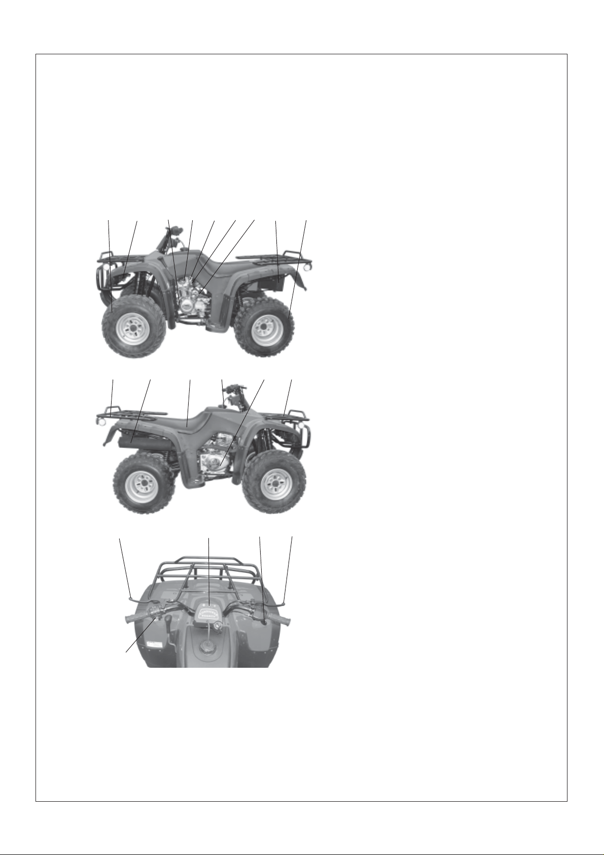
Chapter I General description
Section 1Description
1
10 11
16 17 18 19
3
2
4
12
6
5
13
7
14
8
9
1.Front wheel
2.Headlight
3.Drive select lever
4.Shift pedal
5.Fuel cock
6.Hand-operated lever
7.Air chock
15
8.T ail light
9.Rear wheel
10.Rear luggage carrier
11.Exhaust silencer
12.Cushion
13.Fuel tank cover
14.Rear brake pedal
15.Front luggage carrier
16.Clutch handle
17.Main switch lock
18.Throttle grip
19.Right lever of front brake
20. Left switch unit
20
Caution:
The ATV you purchased maybe slightly differ from the pictures in the manual due to
improvement or other changement.
- 1 -

Section 2 Special tools, instruments and meters
(I) Special tools
Special tools is the necessary tools used for accurately adjustment and assembly, it is
helpful to prevent the maintenance defects and components damage caused by using improper tools.
1.Wrench for valve adjustment mainly used for adjusting valve clearance. Specification:
3mm 90890-01311
2.Puller for piston pin, mainly used of removing piston pin.
3.Remover for rotator, mainly used for pulling magneto rotator from crank.
4. Clamp for rotator, mainly used for clamping magneto rotator when removing it to
prevent its rotation due to torque force.
5.Stop rotating meter for rotator, mainly used for removing and assembling rotator of
kick starter.
6.Puller for crank, mainly used for disassembling crank from crankcase.
7.Puller for rocker shaft, mainly used for removing rocker shaft.
8.Compressing tools for spring of valve, mainly used for fixing and compressing spring
when assembling valve lock clamp.
9. Assembling and disassembling tools for valve guide, mainly used for assembling and
disassembling valve guide.
10.Assembling buffer, mainly used for assembling crank and balancing gear.
11.Hollow sleeve, mainly used for assembling crank and balancing gear .
12.Assembling tools for crank, mainly used for assembling crank and balancing gear.
13.Assembling and disassembling joint for universal coupling, mainly used for assem-
bling and dismsembling universal coupling.
14.Assembling and disassembling disc, mainly used for assembling and disassembling
reverse gear.
15.Fixed puller for gear, mainly used for assembling and disassembling gear.
For the above tools, you can select with reference to special tools of the same
type of vehicle.
- 2 -
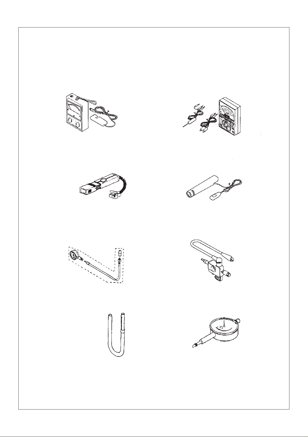
(II) Instruments and meters
The following instruments and meters can be selected with reference to the same type of
vehicle.
speedometer of engine
(90890-03113)
Ignition timing meter
(90890-03141)
multimeter
spark tester of spark plug
barometer ignition checker
measuring tool of gasolining
(90890-01312)
dial indicator
- 3 -
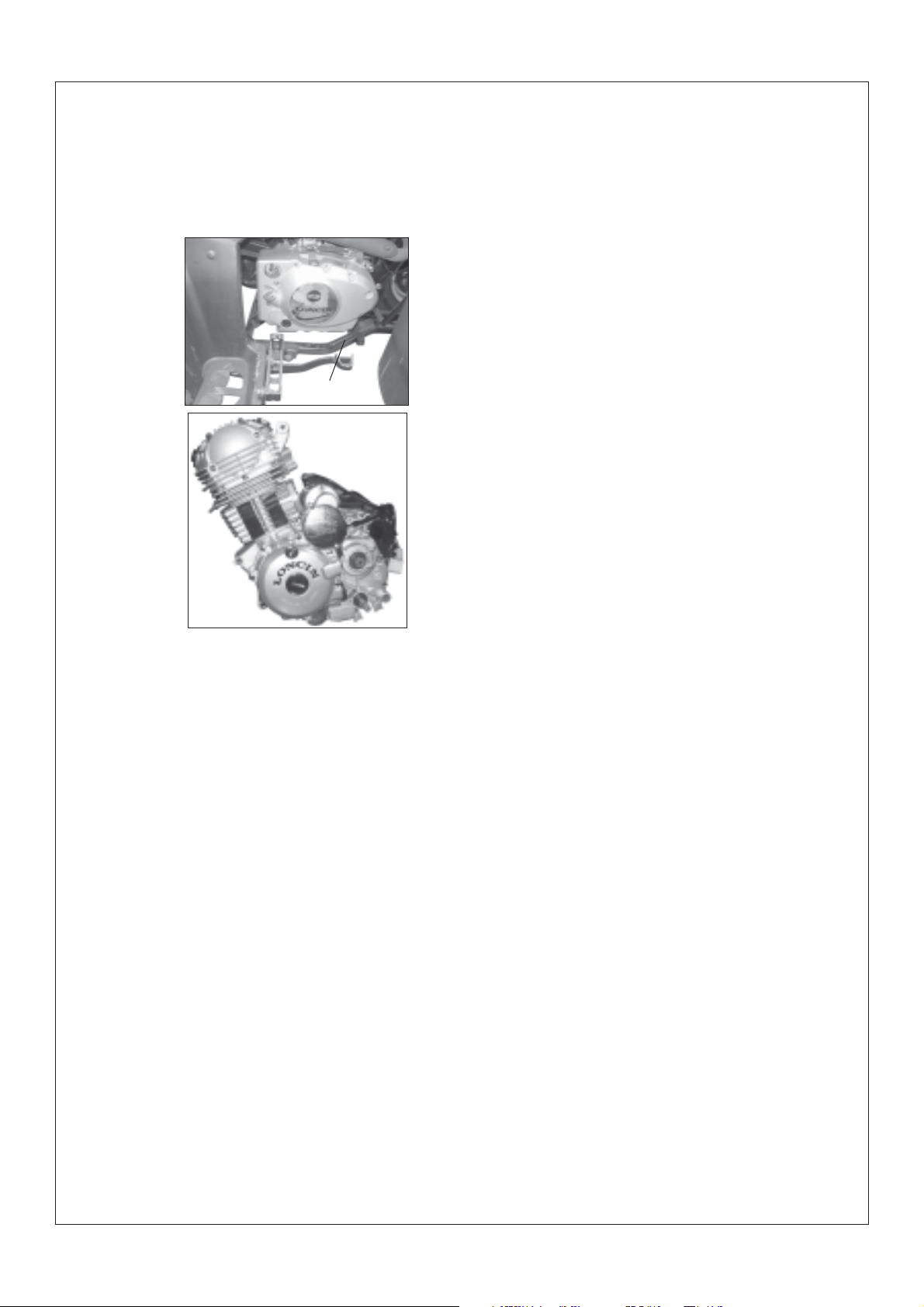
Section 3 Identification code, and engine N0.
Identification code
It is engraved in the left or right side of front
supporting main tube of engine of frame.
¢Ù
Engine N0.
It is engraved on the lug of top middle part of
right crankcases of engine.
Section 4 Points for attention in maintenance
1.Preparation when disassembling
1.1 First clean the dirt, mud and attachment on the vehicle before removing or
disassembling.
1.2 Use proper special tools cleaning device and means.
1.3 Keep all the components away from
fire source. Pay attention to the safety, Don’t
be burned by the high temperature portion of
engine, exhauster and silencer etc. Be sure to
take care of each other when operation with
other people.
1.4 When disassembling the ATV, put the
mated components, such as gear pairs,
cylinder, piston and other “mated” components
by normal running in together, When assembling or replacing these components, they should
be in pairs.
1.5 When disassembling the engine, clean
all the components and put in the tray in the
- 4 -
order of disassembly, this in assembling, can
not only increase the assembling speed, but also
ensure the rightness of assembling.
2.Replace the components
When replacing the components, be sure
to use qualified products provided by use lubricants and grease which brand is assigned by
lubricate.
3.Oil seal, shim, o-ring, clip, split pin,
elastic washer.
3.1 When disassembling to maintain the
engine, in order to ensure that the reassembled
engine have good sealing and connecting part
is fixed and reliable, all the oil seal, shim, oring, clip, split pin and elastic washer should be
replaced, be sure to keep lip of oil seal surface
of shim and o-ring in cleaning condition.
3.2 When reassembling, apply lubricants
to lubricate all the mated components and
bearing, apply grease for oil seal.
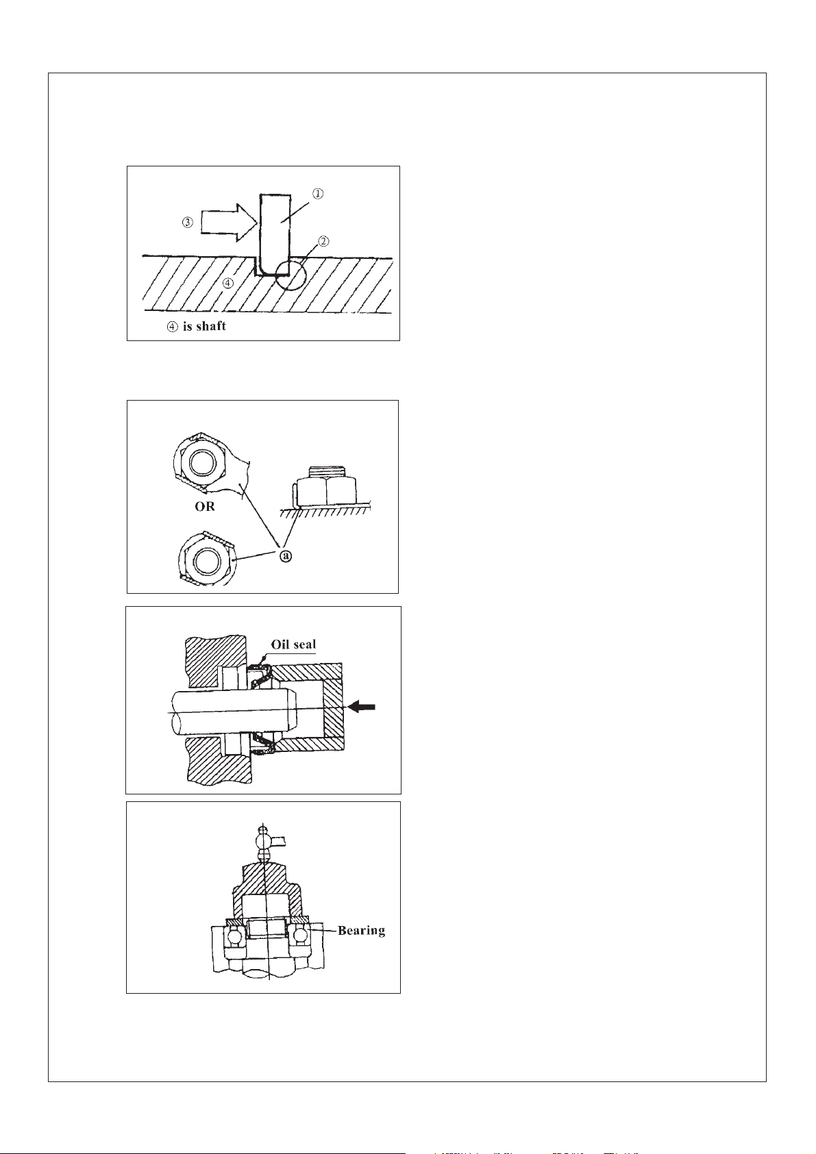
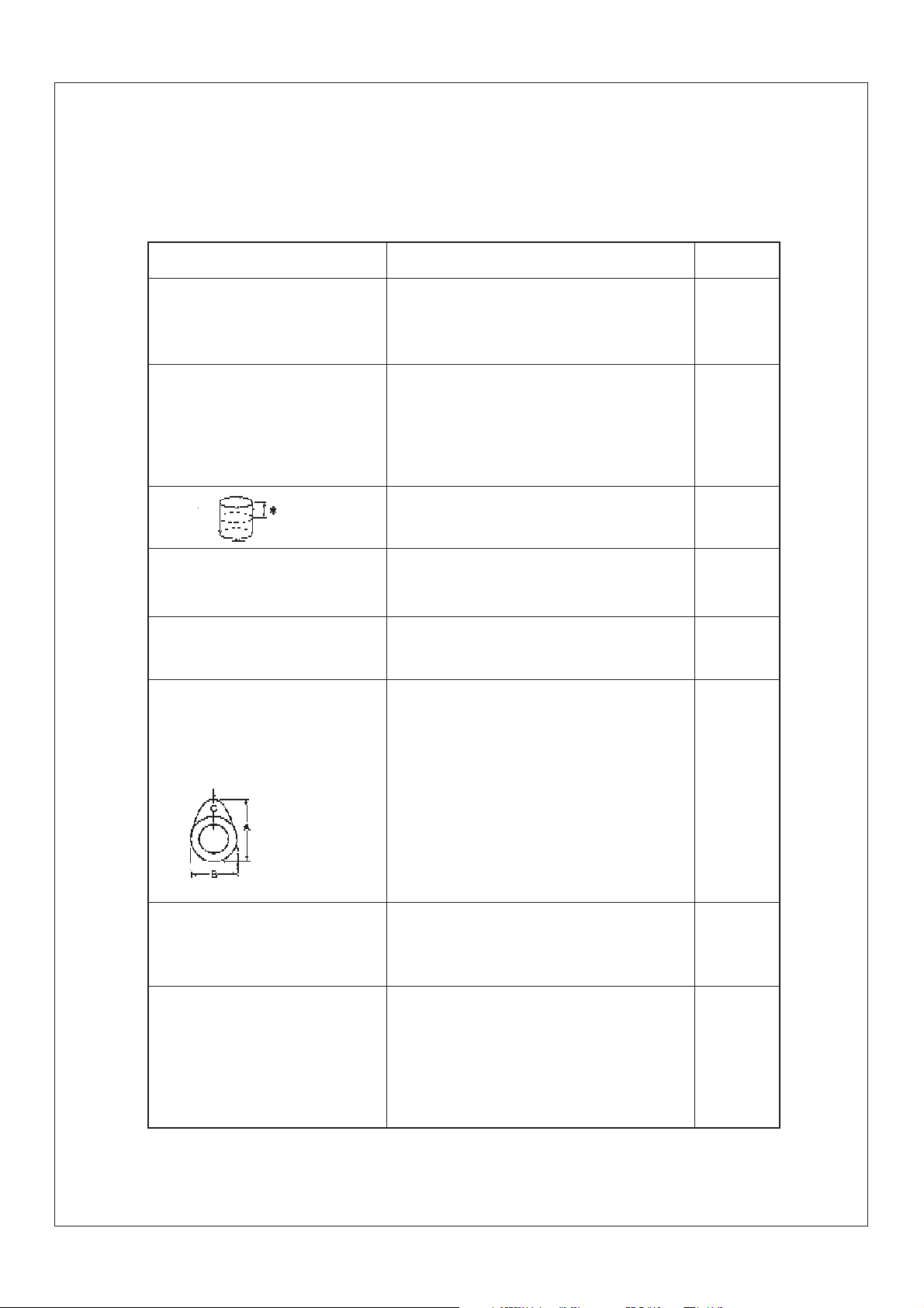
4. Clip
4.1Before assembling, be sure to check
all the clips carefully.Use a new one after removing the clip of piston pin. When mounting
clip ring ¢Ùmake the sharp face ¢Úon the opposite position of impacted face ¢Ûof clip.
(see left fig)
5.Locking washer /shim and location pin
5.1When reassembling after
disassembling. be sure to replace all the locking washer /shim and location pin @ After
bolt or nut is fixed on the locking position. be
sure to bend and fix both ends of locking shim
along head of bolt or direction of nut.
6.Bearing and oil seal
6.1 When assembling bearing and oil seal
put the mark or specification of manufacturer
outside, When assembling oil seal apply a thin
film of lithium-base grease on the lip of oil
seal.
Caution:
Don’t blow to dry the inside of bearing
with compressed air, this would damage the
surface of bearing.
- 5 -
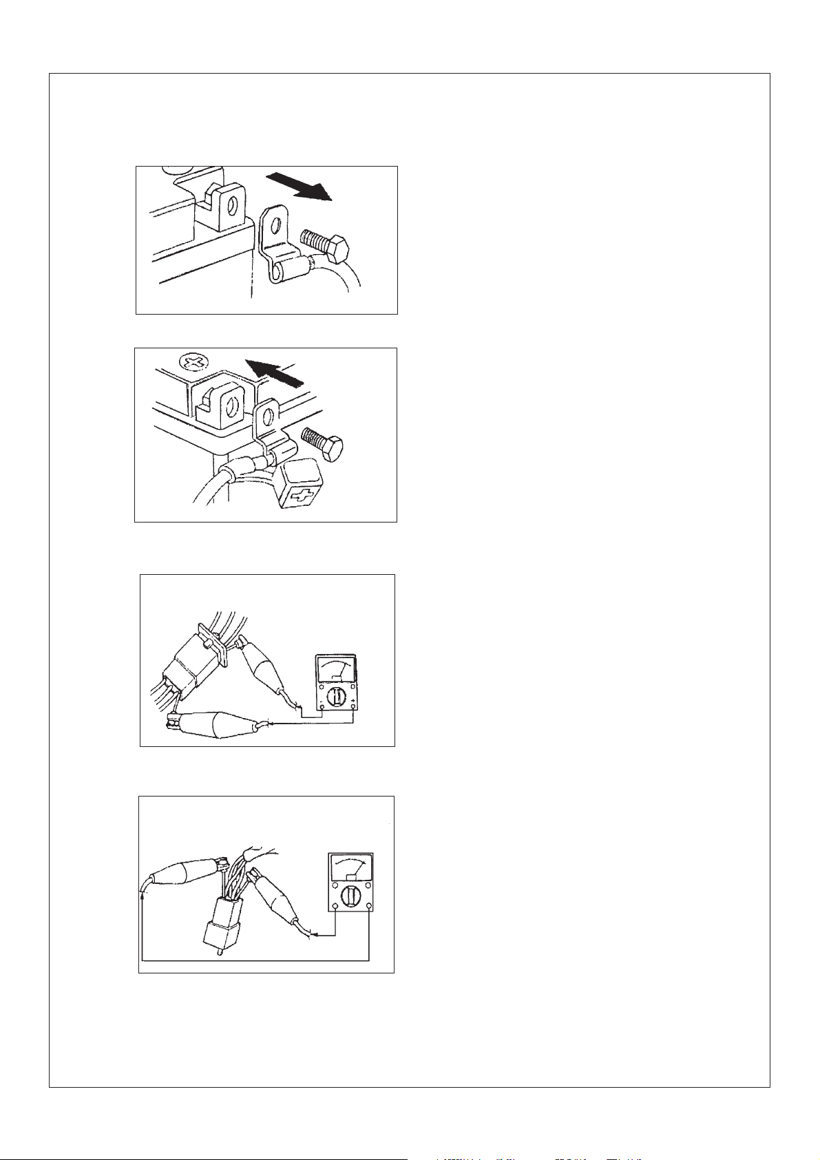
Fig.7.1Removal of negative pole wire of battery
Fig.7.2 Connection of positive pole wire of battery
7.Check of electric parts
7.1 Check the rust, dirt and moisture etc.
of connector, if there is moisture, please blow
it dry and clear the rust and dirt.
7.2 The electrolyte inside the battery is a
kind of corrosive, when operating exercise shall
be taken not to let the electrolyte splash on the
body.
7.3 When repairing wire on electric parts,
first remove the wire on the terminal of negative pole of battery(see fig.7.1).When tightening or loosening bolt of terminal of big capacity battery, don’t let the wrench contact with
engine or other metal parts of vehicle body to
avoid the electric shock.
7.4 When connecting the wire of battery,
first connect the opositive pole wire of battery,
then connect the negative pole wire. After connecting the wire, apply clean grease on the terminal to avoid the increasing of resistance due
to rust.
- 6 -
7.5 Check the terminal of connector
a Grip two terminals of connector together,
check with the multimeter.(see fig.7.3,fig.7.4)
Fig.7.3
Fig.7.4
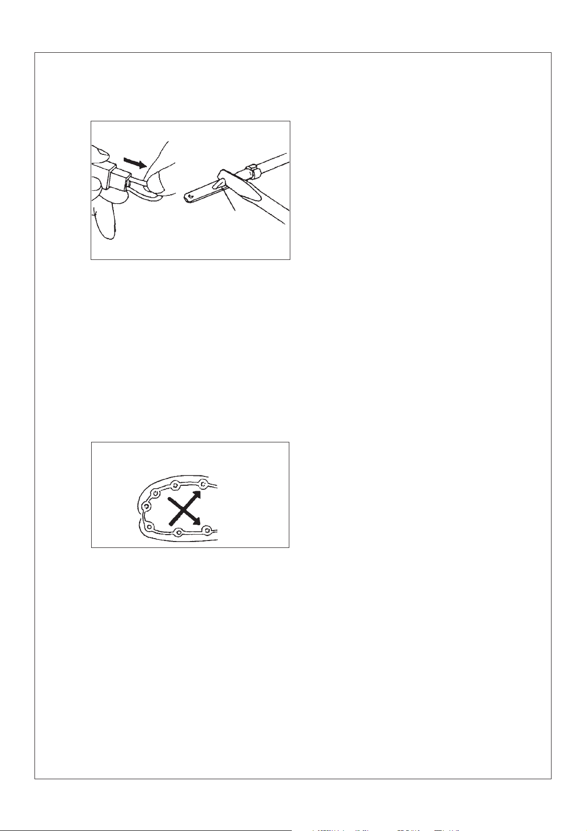
Fig.7.5
b. If joint is slack, bend the plug pin
upward, then connect with connector plug(see
fig7.5)
7.6 Before mounting new fuse, check if
the load of fuse of components is right, especially for the portion being burned broken
regularly, then mount the fuse having proper
current value.
7.7Wire connector have two kinds, one
is single-head connector, another is multi -head
one.
Before connecting single-head connector
,check if there is broken on the housing of
joints, the joint is fixed and if there is a broken
phenomenon on it. When inserting the joint, it
should be fixed, then put in plastic coating after inserting.
In general, multi-head connector is plastic one, and locking catch is designed. When
disassembling the connector, first open locking catch when connecting again, first check
if all the joint is in good condition, if there is
bent or twist on them. After connecting, align
the locking catch and lock them.
Fig.8.1Tightening method of screw and nut.
8. Use torque spanner to tighten screw
and nut, and as per specified torque to tighten
them. It should be tightened in steps from big
ones to small ones, from inside to outside and
along the direction of diagonal line to intersect.
A s shown in fig.8.1.
- 7 -
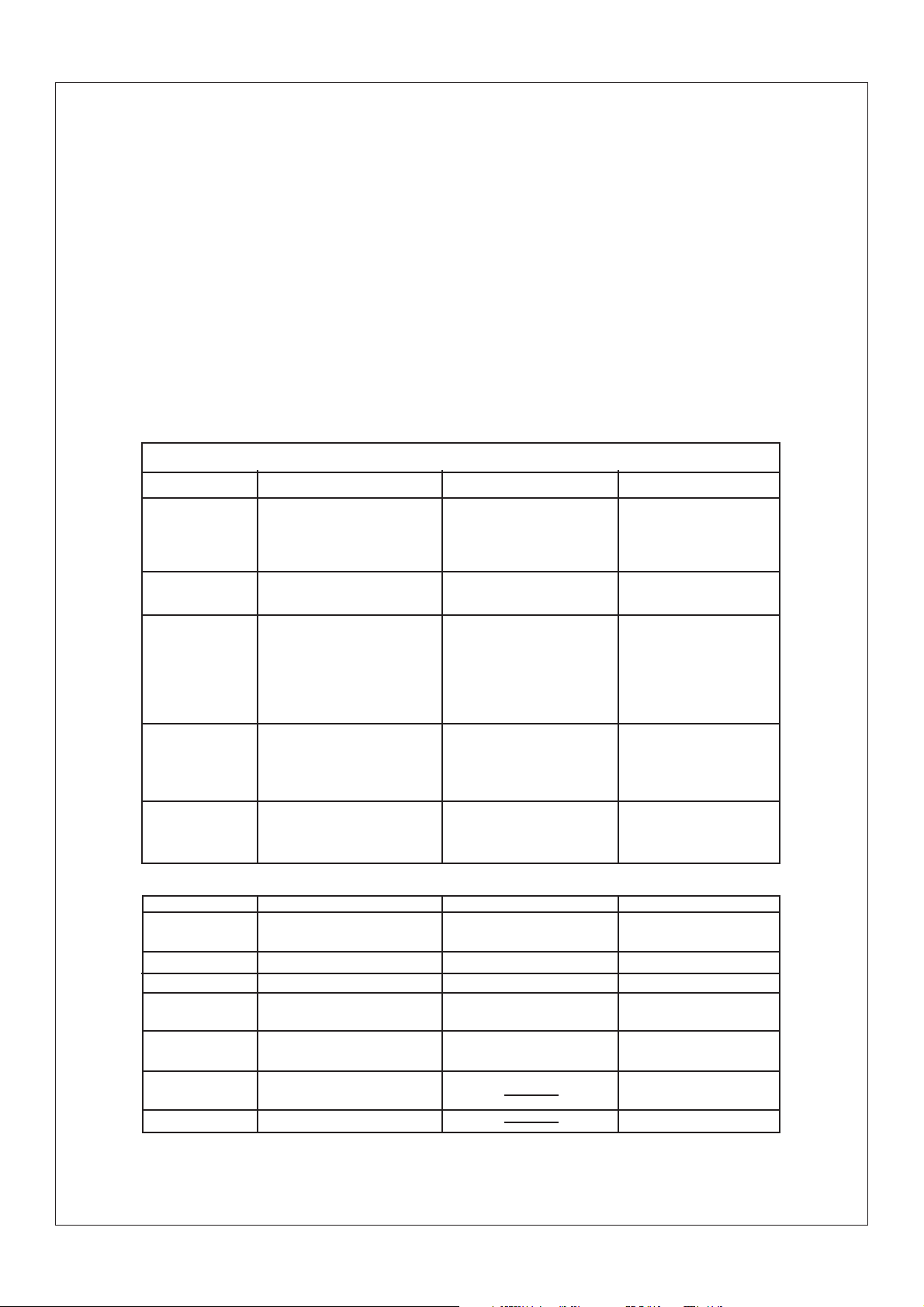
Section 5 Specification
(I) How to use conversion table of unit
(1)How to use conversion table
All the specified documents in this manual are taken SI and Metric as unit. W ith the
following conversion table, metric unit could be conversed into imperial unit.
METRIC MUL TIPLY IMPERIAL
m m 0.03937 in
2mm ¡À 0.03937 = 0.08in
Conversion table
Conversion between metric and imperial
Torque
Weight
Length
Volume/capacity
Others
Known unit
m.kg
m.kg
cm.kg
cm.kg
kg
g
km/hr
km
m
m
cm
mm
cc(cm3)
cc(cm3)
lit(liter)
lit(liter)
kg/mm
2
kg/cm
Centigrade
Multiply
7.233
86.794
0.0723
0.8679
2.205
0.03527
0.6214
0.6214
3.281
1.094
0.3937
0.3937
0.03527
0.06102
0.8799
0.2199
55.997
14.2234
9/5(¡æ)+32
product
ft.lb
in.lb
ft.lb
in.lb
lb
oz
mph
mi
ft
yd
in
in
oz(IMP liq)
cu.in
qt(IMP liq)
gal(IMP liq)
1b/in
psi(1b/in2)
Fahrenheit(0F)
(2)Definition of unit
Unit
mm
cm
kg
N
Nm
m.kg
Pa
N/mm
L
3
cm
r/min
- 8 -
Read
Millimetre
Centimetre
Kilogram
Newton
Newton meter
Meter kilogram
Pascal
Newton per millimeter
Liter
Cubic centimeter
Revolutions per minute
Definition
10-3Meter
10-3Meter
103Gram
1 lilo ¡Ámeter /second
Newton ¡Ámeter
Meter ¡Ákilo
Newton/meter
Newton/centimeter
2
Measurement
Length
Length
Weight
Force
Torque
Torque
Pressure
Rigid of spring
Volume or capacity
Rotational speed
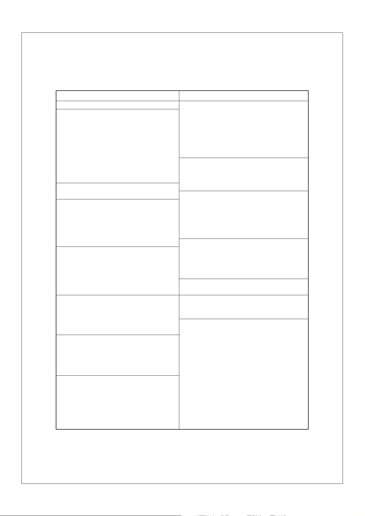
II.Basic specification
Item
Specification
Dimension:
Overall length 1940mm
Overall width 1050mm
Overall height 1160mm
Height of cushion 810mm
Axle base 1160mm
Front wheel distance 785mm
Rear wheel distance 770mm
Min.ground clearance 155mm
Min.turning radius 2900mm
Basic weight:
Engine oil(with full tank) 220kg
Engine Single-cylinder,air-cooled four stroke
Displacement 193.2ML
Cylinder borestroke 6 3 ¡Á62mm
Compression ratio 9.0:1
Starting system Electric starter or handoperated starter
Lubrication system Pressure splash
Engine oil SAE20W/40,SAE15W/40
Classfication of recommendedengine oil Model SE,SF,SG or above model
Periodic oil replacement 1.0L
Replace filter 1.1L
Overall capacity 1.1L
Oil capacity of gearbox 0.27L
Model: SAE80API¡°GL-4”Gear oil of
standard double curved face
Capacity of main fuel tank 12L.Non-lead gasolining No.90#
Capacity of reserved fuel tank 1.6L
Carburetor:
Type PZ30(INJECT PZ30)
Type of spark plug D8EA
Clearance of spark plug 0.6-0.7mm
Type of clutch Wet hand centrifugal type
Output
Primary reduction system Gear driving
Reduction ratio 3.333
Secondary reduction system Axle driving
Reduction ratio 3.742
Output type
Operation Left-foot operation
Non-cycle,five gear forward,gear back
Item
Shifting type
1st speed 2.769
2nd speed 1.882
3rd speed 1.400
4th speed 1.130
5th speed 0.960
Reverse gear 34.427
Frame
Bracket Steel tube
Caster angle 13¡ã
Toe-in of tire 0-5mm
Tire
Type Vacuum
Specification of front wheel AT23 ¡Á7-10
Specification of rear wheel AT22 ¡Á10-10
Pressure of front wheel 20Kpa
Pressure of rear wheel 25Kpa
Brake:
Type of front brake Drum brake(full-closed type)
Operation type Right-hand operation to brake
Type of rear brake Drum brake(full-closed type)
Operation type Right-foot to brake
Front suspension Independent suspension device
Rear suspension Rear centering shock absorbing type
Specification of shock absorber
Front shock absorber spring
Rear shock absorber spring
Electric system:
Ignition system C.D.I
Magneto system A.C magneto
Battery/capacity Free of maintenance,
12V,14AH
Headlight 12V,30W/30W ¡Á2
Taillight 12V,10W¡Á1
Neutral indicator 12V,3W ¡Á1
Reverse indicator 12V,3W ¡Á1
High-beam indicator 12V,3W ¡Á1
Specification
- 9 -
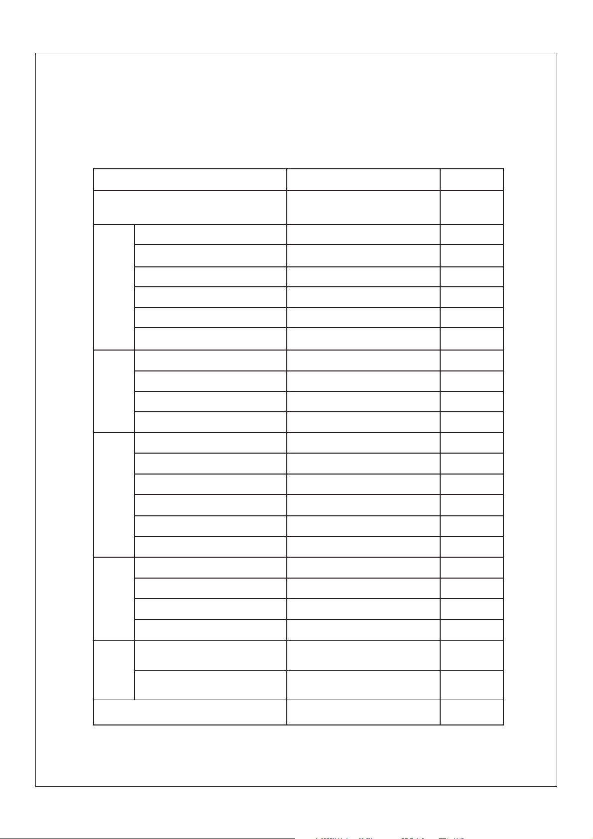
III.ATV body
Steering system
Type of steering bearing
Type
Material of rim
Front
wheel
Front
brake
Size of tire
Size of rim
Radial runout of rim
Lateral swing of rim
Type
Inside diameter of brake drum
Thickness of friction piece
Free length of back spring of brake shoe
Type
Material of rim
Item
Standard Limit
Powder metallurgic sliding bearing
Spoke rim, tubeless tire
Steel plate
AT 23 ¡Á7-10
AT 10 ¡Á5.5
Drum type
160mn
4.0mm
71.0mm
Spoke rim, tubeless tire
Steel plate
2.0mm
2.0mm
161mm
2.0mm
Rear
wheel
Rear
brake
Brake
lever and
brake
pedal
Free play of throttle grip
- 10 -
Size of tire
Size of rim
Radial runout of rim
Lateral swing of rim
Type
Outside diameter of brake drum
Thickness of friction piece
Free length of back spring of brake shoe
Free play of brake lever (right)
Free play of rear brake pedal
AT 24¡Á10-10
AT 10 ¡Á8.0
Drum type
160mm
4.0mm
71.0mm
5-7mm
20-30mm
3-5mm
2.0mm
2.0mm
161mm
2.0mm
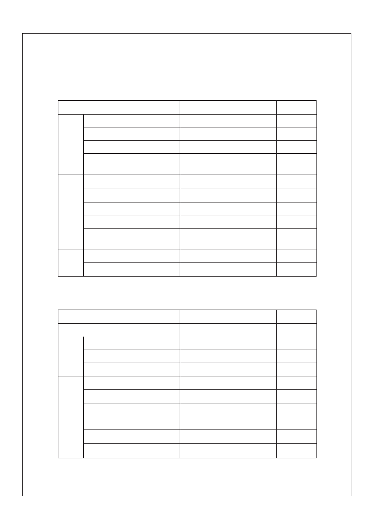
Item
Standard Limit
Elastic coefficient of spring K1
Front
suspen-
sion
system
Rear
suspen-
sion
system
Rear
wheel
Free length of suspending spring
Stoke of shock absorber
Pre-tension force of spring is
adjsutable or not
Elastic coefficient K2
Free length of suspending spring
Assembling length
Stroke of shock absorber
Pre-tension force of spring is adjustable of not
Assembling free play(left-end)
Assembling free play (right-end)_
fork
IV.Electric system
10N/mm/0-117mm
293mm
117mm
Can’t adjustable
49N/mm/0-85mm
263mm
244mm
85mm
Adjustable
1.0mm
1.0mm
Spark
plug
Ignition
coil
Ignition
system
Item
Voltage of electric system
Type
Resistance
Clearance of spark plug
Resistance of primary coil
Resistance of secondary coil
Clearance of min. spark
Ignition timing (Before upper stop point)
Advancing angle of ignition (Before upper stop point)
Type of ignition advance
Standard Limit
12V
D8EA
10¦¸
0.6-0.7mm
At 20¡æ(680F),0.5-1.5¦¸
At 20¡æ(680F),4.6-7.6¦¸
6mm(0.24in)
10/2300r/min
5500¡À200r/min
Electric type
- 11 -
Item
Standard Limit
Magneto
Rectifier
Charging
system
Battery
Broken
circuit of
circuit
system
Relay of
cut-off
current
Resistance of induction coil/colour
Resistance of source coil /colour
T ype of C.D.I
No-loading adjusting voltage
Voltage-resisting value
Type
Rated ouput voltage
Coil resistance/colour
Specific gravity
Capacity
Type
Main fuse
Reserved fuse
Coil resistance
Diode
At 20¡æ(680F),189-231¦¸ Blue black
At 20¡æ(680F),470-530¦¸ Yellow/green-red
Electric capacity contactless type
14.1-14.9V
200V
A.C magneto
At 2000r/min 14-15V
At 20¡æ(680F),1.0-1.2¦¸ White -white
1.28
12V.14Ah
Fuse
20A
20A
At 20¡æ(680F),72-88¦¸
Yes
Electric
starting
system
Electric
starting
system
- 12 -
Type
Starting
motor
Starting
relay
Output power
Resistance of armature coils
Ampere
Coils resistance
Constant mesh type
0.35KW
At 20¡æ(680F),0.004-0.005¦¸
100A
At 20¡æ(680F),4.8-5.3¦¸
V.Maintenance specification of engine
Item
Axle drive
Meshing clearance of last end gear
Meshing clearance of middle gear(forward)
Meshing clearance of middle gear(backword)
Lubrication system:
Type of filtering oil
Type of oil pump
Clearance of side
Endface clearance”A”or “B”
Releasing pressure of safety valve
Cylinder
Bore size
Cylinder head
Flatenss of lower endface
Timing chain
Type of timing chain
Tension type of timing chain
Camshaft:
Driving method
Roundness tolerance of camshaft
Outside diameter of camshaft
Cam size
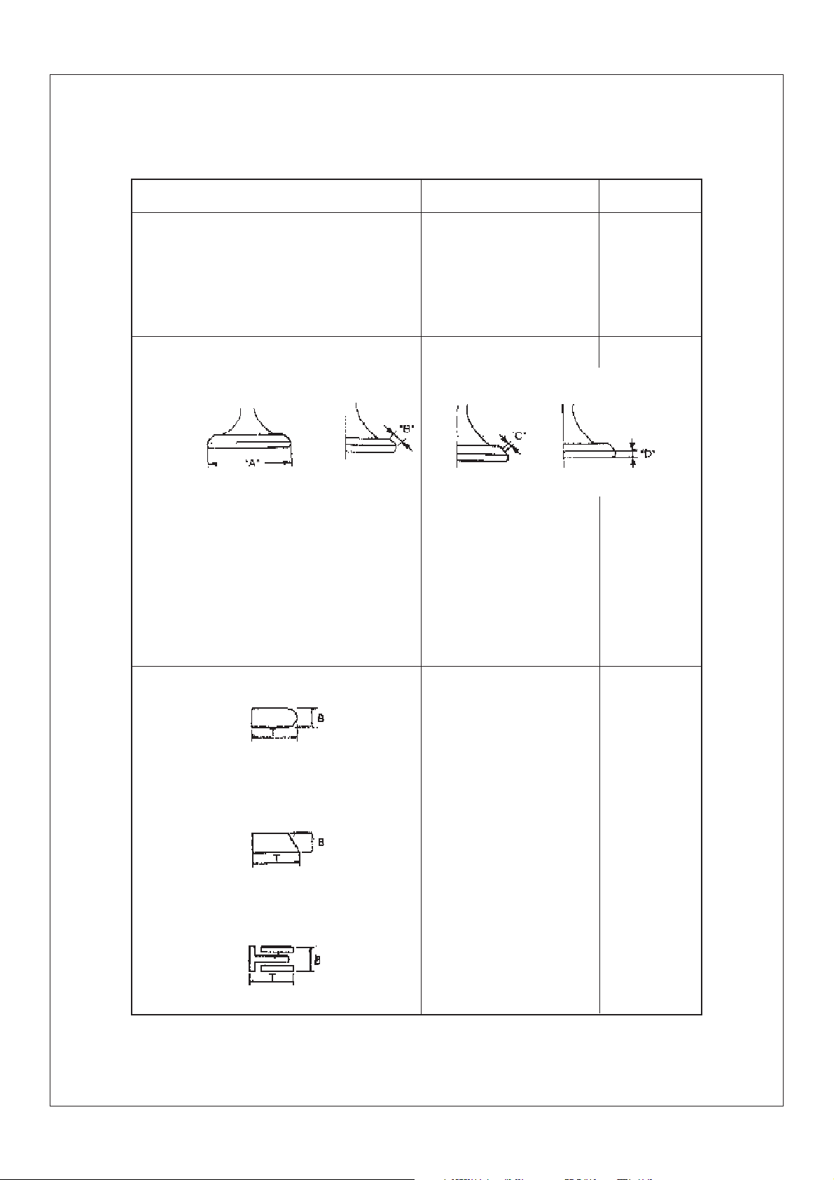
Exhaust:¡°A”
¡°B”
“C”
Intake:“A”
“B”
“C”
Rocker arm/Rocker arm shaft
Outside diameter of shaft
Inside diameter of rocker arm
Clearance between arm and shaft
Standard
0.1-0.2mm
0.1-0.2mm
0.10-0.25mm
Wire filtering net
Rotor type,pressure splash type lubrication
0.05mm
0.20mm
80-120Kpa
§¶63.025mm
(Distance between measuring point and upper endface
of cylinder is 40mm)
Measure the surface warp of every portion on the
lower endface of cylinder head with rule.
Roller chain
Free adjustment
Shaft driving(left)
§¶25mm
31.365mm
25mm
6.365mm
31.532mm
25mm
6.532mm
-0.006
§¶12
-0.024
+0.018
§¶12
-0
0.006~0.042
Limit
0.10mm
0.50mm
§¶63.03
§¶63.02mm
0.10mm
0.02mm
¡À0.04
¡À0.01
¡À0.06
¡À0.04mm
¡À0.01mm
¡À0.06mm
Valve spring
Inside spring
Free length:intake/exhaust
Setting length when valve is closed:intake/exhaust
Compressing pressure when assembling:intake/exhaust
Limit value of squareness:intake/exhaust
Twisting direction of spring(top view):intake/exhaust
35.5mm
30.5mm
82.4-100.0N
2.5¡ã/1.6mm
Counterclockwise
- 13 -
Valve spring
Outside spring:
Free length:intake/exhaust
Setting length when valve is closed:
Compressing pressure when asembling:intake/exhause
Limit value of squareness:intake/exhaust
Twisting direction of spring(top view):intake/exhaust
Valve,Valve seat,valve guide
Valve clearance(it s cold):intake
exhaust
Size of valve
StandardItem
37.2mm
32.0mm
162.8-200.1N
Clockwise
0.05-0.09mm
0.11-0.15mm
Limit value
2.5¡ã/1.6mm
“A”diameter of valve head
“B” width of valve face
“C” width of valve seat
“D”limit thickness
Outside diameter of valve stem
Inside diameter of valve guide
Clearance between valve stem and guide:exhaust
Roundness of valve seen
Piston ring
First ring
Type
Size(B ¡ÁT)
Clearance of endface(in assembling)
Clearance of side(in assembling)
Second ring
Type
Size(B ¡ÁT)
Clearance of endface(in assembling)
Clearance of side(in assembling)
Oil ring
exhaust
intake
intake/exhaust
intake/exhaust
intake/exhaust
exhaust
intake
intake/exhaust
intake
28.4-28.6mm
33.9-34.1mm
1.7-2.8mm
0.9-1.1mm
0.8-1.2mm
5.960-5.975mm
5.975-5.990mm
6.000-6.012mm
0.025-0.052mm
0.10-0.037mm
Bucket-shaped back round
1 ¡Á2.5mm
0.25mm
0.035mm
Flat type
1 ¡Á2.6mm
0.25mm
0.035mm
1.6mm
0.10mm
0.08mm
0.03mm
0.35mm
0.05mm
0.35mm
0.05mm
Size(B¡ÁT)
Clearance of endface(in assembling)
- 14 -
2 ¡Á1.78mm
0.4mm
0.7mm
Item
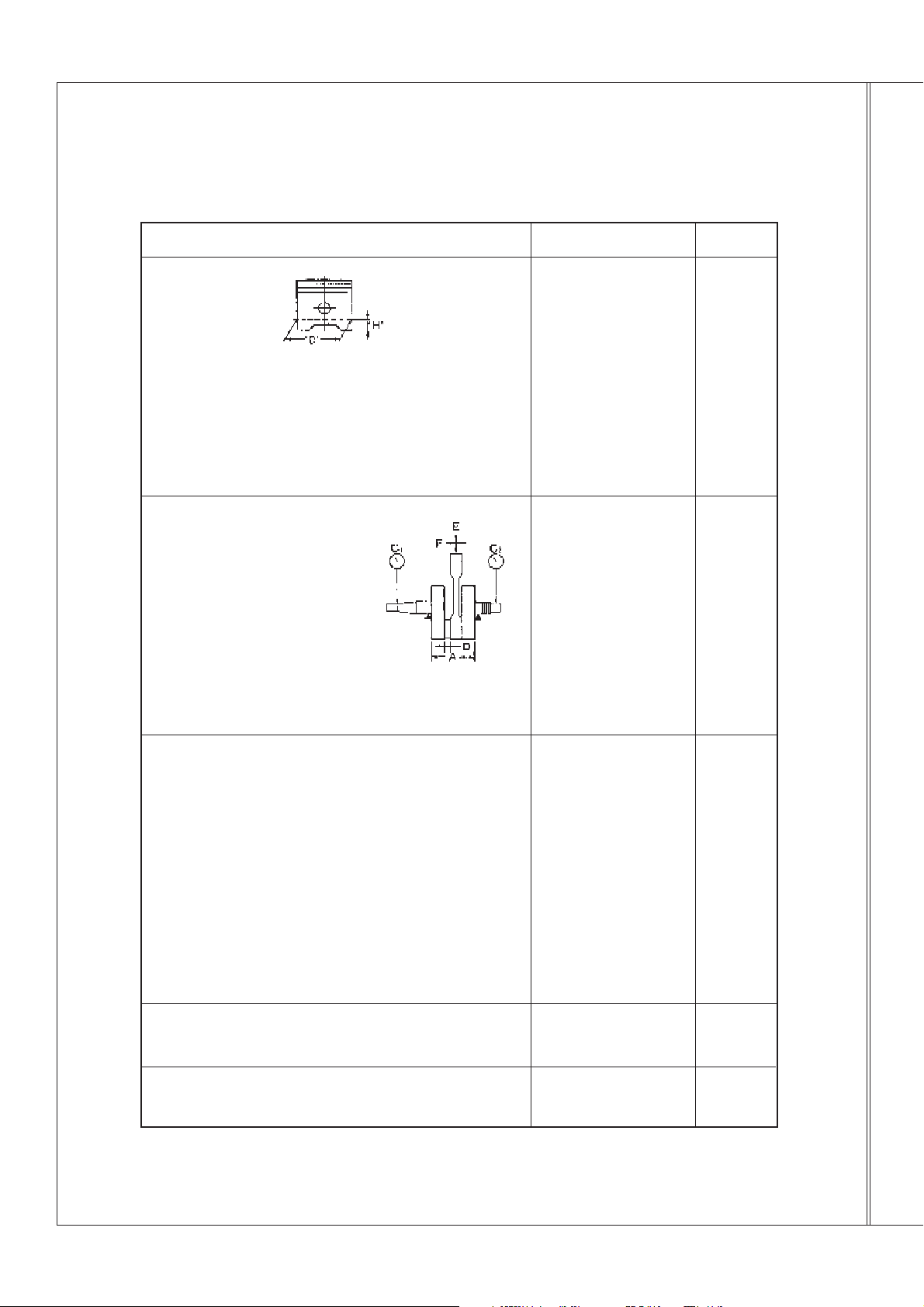
Piston
Piston size”D”
Measuring point’H”(from bottom line of piston’s lower portion)
Piston offset
Direction of piston offset
Clearance between piston and cylinder
Outside diameter of piston pin
Inside diameter of pin hole
Connecting rod of crank
Standard
-0.01
§¶63
-0.03
11.5mm
0.5mm
Inward
0.035mm
0
§¶15
-0.006
16.002-16.013mm
+0.01
§¶15
-0.002
Limit value
0.06mm
Limit value of runout:C1
C2
Width of crank¡°A”
Small end free play of connecting rod “F”
Big end free play of connecting rod “D”
Big end radial clearance of connecting rod“E”
Hand
Revolution
Clutch:
Action method of clutch
Clutch piece:quantity
thickness
Friction piece:quantity
thickness
Spring of clutch:quantity
free length
Shifting method
Bending limit of fork guide
Transmission device
Offset limit of spindle
Offset limit of transmission output shaft
+0.05mm
55
-0mm
0.30~0.70mm
0.1~0.35mm
0.008~0.012mm
Outside pushing type
5 pieces
1.2mm
6 pieces
2.9mm
6
35.3mm
Shift gear cam drum and
fork
0.03mm
0.03mm
0.8mm
0.08mm
0.08mm
- 15 -
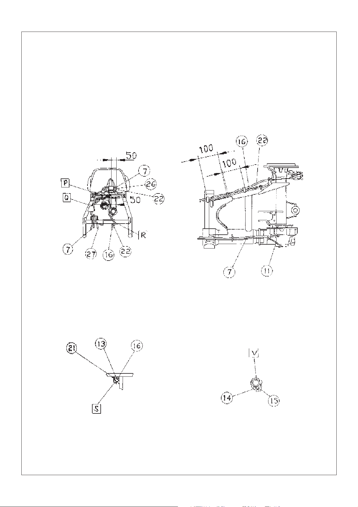
Section 6 W iring diagram of ATV
(I)T echnical explanation and requirement, details of relative component.
1.Technical explanation
A Main switch wire, indicator wire, mile-
age meter wire (mounting digital mileage
meter) must be put throught the guide grip of
holding seat of steering bar. (see fig.1)
B Rear brake vent-pipe, carburetor vent-
pipe and vent-pipe of rear driving gearbox must
be inserted into the hole of supporting pad of
vent-pipe.(see fig.1, also see view D)
C Neutral and reverse switch wire,
mileage meter wire(mounting with digital
mileage meter) should be fixed with bands
here.(see fig.1)
D After putting overflowing pipe of car-
buretor through two rear fixing part of engine
(on the frame), then put it in the proper position between engine and rear arm. Note: Overflowing pipe be unblocked.(see fig.1)
S After putting rear brake cable, throttle
cable, wire of starting motor and mileage meter
(mounting with digital mileage meter )through
wire hook2, wire hook 2should be bent according to the method of view A.
P In this position, starting motor wire
and mileage meter wire(mounting with digital
mileage meter)must be put through the hole of
plastic grip in the fuel tank support of frame..
(see view B-B)
R In here, rear brake cable, rear brake
vent-pipe and mileage wire(mounting with digital mileage meter)must be first put through wire
hook 2, then connect with respective matching unit.(see fig. B-B)
Q In here, wire of reverse switch neutral
switch, and mileage meter (mounting with digital mileage meter)must be fixed with bands.
(see fig.B-B)
T When assembling the wire of ser. No.
14 and No.15.don’t need to put through the
guide clip of holding seat of steering bar.(see
fig.E-E)
W After putting the vent-pipe of tank
through the hole of main switch, lead it to the
lower of right side of steering bar, then put it
through the wire hook on the frame.
Note: Hose must be unblocked.(see fig.
E-E)
V The leading wire on the switch units of
steering bar, must be bound with band,(see fig.
G-G)
E After the vent-pipe of front brake is put
through plastic clip hole on the frame, surplus
portion should be put in the proper position of
frame.(see fig.2)
G After the vent-pipe of battery is checked
and no twist is found here, then insert it in the
presetting hole of rear fender.(If free of maintenance battery is used, then this item of requirement doesn’t need.)(see fig.3)
H Wire of rear brake cable, rear brake
vent-pipe and mileage meter(mounting with digital mileage meter)should be put through the cable
frame welded on the frame in here.(see fig.3)
F In here, wire of starting motor must
be first put through the plastic clip on the
frame, then connect with the matching units.
(see fig.3)
L Vent-pipe of battery should be put
through the plastic clip fixed on the frame.(see
fig..)(If free of maintenance battery is used,
then this item of requirement doesn’t need.)
K In here, wire of throttle cable, rear
brake cable and mileage meter(mounting with
digital mileage meter )should be put through the
cable guide frame welded on the frame.
(Throttle cable
- 16 -
should be mounted on the inner side of guide
frame direction).(see fig.4)
J Insert the starting relay into the inserter
preset by the rear fender, the direction should be
ensured the convenience of inserting.(see fig.4)
M After putting the vent pipe of battery
through the plastic clip mounted on the rear
fender, insert it into the hole preset by the rear
fender, (Combine with G)(see fig.4)(If free of
maintenance battery is used. then this item of
requirement doesn’t need).
U When assembling, mounting supporting
pad of vent-pipe shouldn’t be leaked, and pay
attention to let the direction of mark upward.
(see view D )
N In here, the wire of taillight must be put
through the slot hole preset by tool kit from the
bottom of tool kit.(see view F)
2.Technical requirement
¢ÙIn the drawing, the wiring condition and
position for all kinds of wires on the ATV body
is marked. When assembling the finished ATV,
wiring should be done as per the drawing in
principle.
¢ÚFor the wiring and fixing method which
can’t be marked in the drawing , necessary technical explanation has been made, you should abide
to execute in assembling.
¢ÛFor the place of using plastic clip stipulated in the drawing, if can’t be used temporarily,
you can use band to fix it.
¢ÜThe dimension in the drawing is only used
for reference in operation, while not be used as
checking data. In the details of marking the code
No. of component, the self-carrying component
(wire etc.)of units only be marked with name.
3.Details of relative component
33
SSA0-000512-0
32
SSA0-000511-0
31
SSA0-000510-0
30
SSA0-000509-0
29
28
27
26
25
24
SSA5-320000-0
23
SSA0-000516-0
22
21
20
19
SSA0-000515-0
18
SSA4-230000-0
17
16
SSA4-230000-0
15
14
13
SSA4-210000-0
12
SSA4-220000-0
11
10
9
8
7
SSA0-000517-0
6
5
4
3
2
SSA5-510000-0
1
SSA0-012000-0
Ser.No.
150.00-0.39
150.00-03
150.00-06
FG-802000-0
SS45-630000-0
FG-803000-0
FG-805000-0
Code
Wire clip 4
Wire clip 3
Wire clip 2
Wire clip 1
Cable band
band of steering bar
C.D.I magneto wire
Vent-pipe of carburetor
Cut-off relay
Starting relay
Cable
Ven-pipe of rear brake
Wire of starting motor
High voltage coils and wire
Vent-pipe of battery
Vent-pipe of front
Wire of headlight
Rear brake cable
Wire of handle bar switch
Wire of clutch wire
Throttle cable
Front brake cable units
Wire of mileage meter
Wire of neutral switch
Wire of reverse switch
Overflowing hose of carburetor
Vent-pipe of gearbox
Taillight unit
C.D.I
Rectifier
Vent-pipe of gearbox
Main switch lock
Wire clip unit
Name
3
2
3
2
6
2
1
1
1
1
1
1
1
1
1
1
1
1
1
1
1
1
1
1
1
1
1
1
1
1
1
1
1
Q’ty
Remark
- 17 -
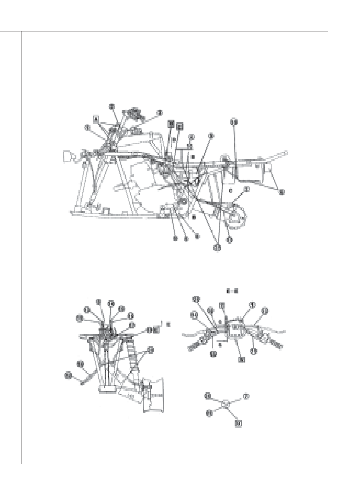
(II)Wiring diagram(1)
E L
Fig.1
- 18 -
Fig.2
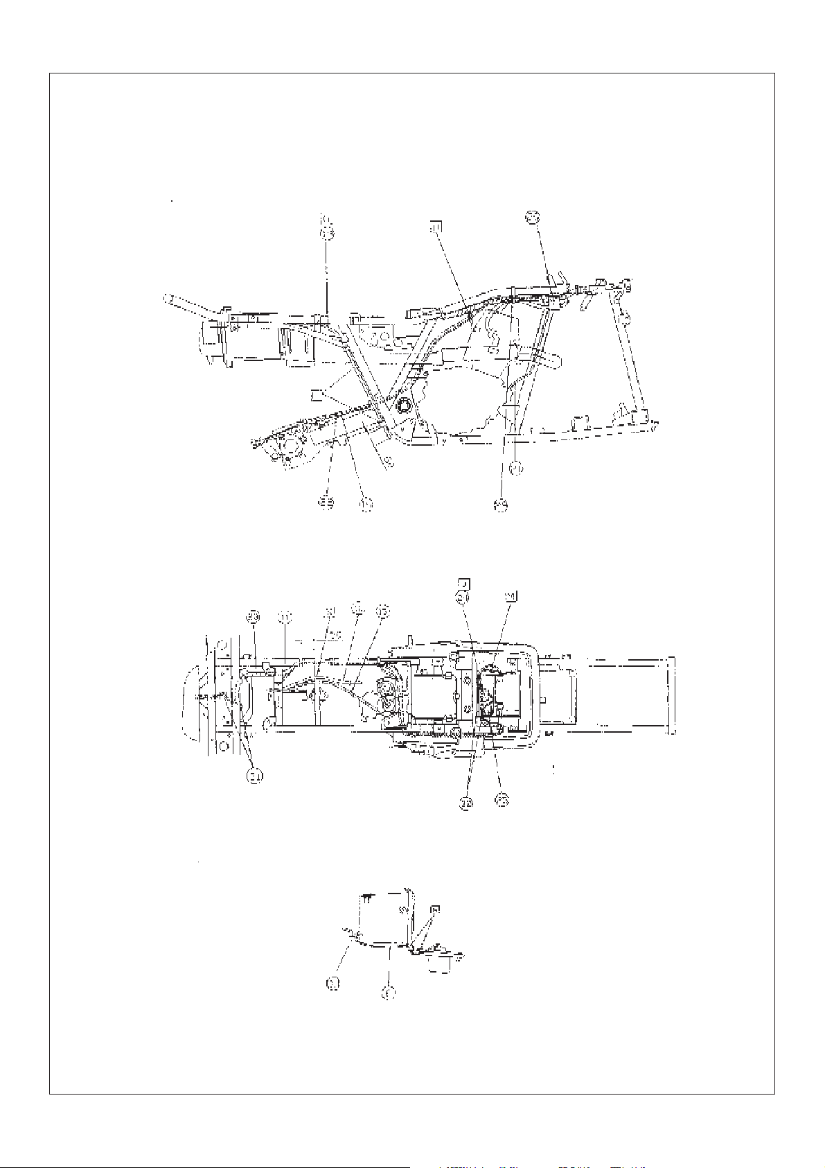
(III)Wiring diagram(2)
Fig.3
Fig.4
F
View F
- 19 -
(IV)Wiring diagram(3)
B-B
View C
- 20 -
View A
G-G
Section 7 Requirements for torque of fastener
(I)A TV body
Torque value of fastener
Locking component and
location of ATV body
Name of
component
Size of
thread
Q’ty
Tightening torque of
fastener of ATV body
Nm
m.kg
ft.lb
Remark
Front wheel rim and front brake hub
Front brake hub and steering vertical post units
Fornt brake cam arm and cam shaft
Front brake and front shock absorber
Front shock absorber and frame
Steering vertical post and pulling rod
pulling rod and nut
Steering vertical post and pulling rod
Steering vertical post(lower)and frame
Holding seat of steering vertical post and frame
Steering vertical post and upper & lower holding seat of steering bar
Front wheel fork and frame
Front wheel fork and brake
Engine upper connection plate unit and frame(upper )
Engine assy and engine upper connecting plate unit
Engine assy and frame(front)
Nut
Nut
Nut
Bolt
Nut
Nut
Nut
Nut
Nut
Bolt
Bolt
Bolt
Nut
Bolt
Bolt
Bolt
M10¡Á1.25
M12¡Á1.25
M6 ¡Á30
M12¡Á50
M35¡Á1.5
M12¡Á1.25
M12¡Á1.25
M12¡Á1.25
M10
M8 ¡Á60
M8 ¡Á50
M10¡Á70
M12¡Á1.25
M8 ¡Á6
M8 ¡Á55
M8¡Á105
8
55
5.5
40
2
25
2.5
18
2
9
0.9
6.5
4
78
7.8
56
2
55
5.5
40
2
25
2.5
18
4
30
3
22
2
25
2.5
18
1
30
3
22
2
23
2.3
17
4
20
2
14
4
45
4.5
32
2
25
2.5
18
2
33
3.3
24
1
33
3.3
24
1
48
4.8
35
Engine assy and frame(rear upper)
Engine assy and frame(rear lower)
Front fender and frame
Front fender flap and front fender supporting rod
Bumper and frame
Front luggage carrier and bumper
Front luggage carrier and frame
Front fender and front luggage carrier
Rear fender and frame
Rear luggage carrier and frame
Bolt
Bolt
Bolt
Screw
Bolt
Bolt
Bolt
Bolt
Bolt
Nut
M8¡Á105
M6 ¡Á16
M6 ¡Á16
M6 ¡Á16
M8 ¡Á16
M6 ¡Á16
M8 ¡Á16
M6 ¡Á20
M6 ¡Á16
M6 ¡Á40
1
33
3.3
24
1
33
3.3
24
2
7
0.7
5.1
2
7
0.7
5.1
4
11
1.1
8
2
11
1.1
8
2
34
3.4
25
2
7
0.7
5.1
2
7
0.7
5.1
2
7
0.7
5.1
- 21 -
Locking component and
location of ATV body
Name of
component
Size of
thread
Q’ty
Tightening torque of
fastener of ATV body
Nm
m.kg
ft.lb
Remark
Rear fender and rear luggage carrier
Left&right foot rest and frame
Left&right foot rest and frame
Supporting weldment in foot rest and bracket weldment
Rear rim and hub
Rear wheel axle and nut
Rear brake cam arm and cam shaft
Rear brake shoe and rear axle housing
Rear wheel fork and frame(left)
Rear wheel fork and frame(right)
Rear arm shaft and nut(right)
Rear wheel fork unit and rear driving gearbox units
Rear wheel axle bushing and driving gearbox units
Rear shock absorber(upper)and frame
Lower cover of gearbox
Bolt
Bolt
Bolt
Bolt
Bolt
Nut
Nut
Nut
Bolt
Bolt
Bolt
Nut
Nut
Bolt
Bolt
Bolt
M8 ¡Á16
M6 ¡Á20
M10¡Á22
M8 ¡Á16
M8 ¡Á16
M10¡Á1.25
M16
M6 ¡Á30
M8¡Á1.25
M22¡Á1.25
M22¡Á1.5
M22¡Á1.5
M22¡Á1.5
M12 ¡Á1.25 ¡Á25
M12¡Á75
M8 ¡Á12
2
34
3.4
25
2
7
0.7
5.1
4
65
6.5
47
2
30
3
22
4
30
3
22
8
55
5.5
40
2
150
15
110
1
9
0.9
6.5
4
28
2.8
20
1
130
13
94
1
6
0.6
4.3
1
130
13
94
4
55
5.5
40
4
55
5.5
40
1
50
5
36
2
17
1.7
12
Rear wheel axle bushing and rear wheel fork unit
Fuel tank and frame
Oil draining bolt of rear driving gearbox
Oiling bolt of rear driving gearbox
- 22 -
Bolt
Bolt
Bolt
Bolt
M12 ¡Á1.25 ¡Á25
M6 ¡Á35
M12¡Á1.25
M12¡Á1.25
4
103
10.3
74
2
10
1
7.2
1
23
2.3
17
1
23
2.3
17
(II) Engine
Torque value of fastener
Locking component and
location of ATV body
Name of
component
Size of
thread
Q’ty
Tightening torque of
fastener of ATV body
Nm
m.kg
ft.lb
Remark
Observing screw hole of cylinder head
Cylinder head
Cylinder head and cylinder
Sprocket cover
Valve cover
Bearing stop plate of camshaft
Spark plug
Cylinder
Balancing shaft gear
Starting ratchet disc
Locking nut(adjusting screw of valve clearance)
Cam timing sprocket
Chain tensioner
Chain tensioner cover
Upper guide plate of chain
Oil pump
Cap shaped nut
Flange bolt
Bolt
Screw
Bolt
Bolt
Nut
Bolt
Nut
Bolt
Nut
Bolt
Bolt
Bolt
Bolt
Screw
M6
M8
M8
M6
M6
M6
M12
M6
M14¡Á1.0
M10¡Á1.25
M6
M10
M6
M6
M6
M6
1
7
0.7
5.1
4
22
2.2
2
22
2.2
2
7
0.7
5
10
1
2
8
0.8
1
17.5
1.75
2
10
1
1
50
5
1
50
5
2
14
1.4
1
60
6
2
10
1
1
7
0.7
2
8
0.8
3
7
0.7
16
16
5.1
7.2
5.8
12.5
7.2
36
36
10
43
7.2
5.1
5.8
5.1
Apply oil
to washer
Apply oil
to washer
Apply oil
to washer
Oil draining screw plug
Fine filter cover of engine oil(drainingoil)
Fine filter cover of engine oil
Carburetor seat and cylinder head
Carburetor and carburetor seat
Carburetor and carbuetor connecting pipe
Air filter box and carburetor connecting pipe
Air filter box and intake pipe
Silencer and frame
Silencer and exhaust pipe
Plug
Bolt
Bolt
Bolt
Bolt
Hose clip
Hose clip
Hose clip
Bolt
Bolt
M35
M6
M6
M6
M6
M5
M5
M5
M8
M8
1
43
4.3
31
1
10
1
7.2
2
10
1
7.2
2
12
1.2
2
12
1.2
1
2
0.2
1
2
0.2
1
2
0.2
2
34
3.4
1
20
2
8.7
8.7
1.4
1.4
1.4
25
1.4
Twist with cable
guide part
- 23 -
Locking component and
location of ATV body
Name of
component
Size of
thread
Q’ty
Tightening torque of
fastener of ATV body
Nm
m.kg
ft.lb
Remark
Exhaust pipe
Crankcase(closing case)
Left side cover
Left crankcase cover
Right crankcase cover
Bearing clamp of right crankcase cover
Bearing clamp of left crankcase cover
Right connecting box
Main clutch
Assistant clutch spring
Assistant clutch hub
Shift cam star-shaped gear
Locking nut
(clutch releasing adjustable screw)
Starting surpassing clutch
Connecting plate of starting motor
Output
Left case bearing clamp of driving shaft
Rear cover bearing
Rear cover bearing
Reverse gear
Rear cover
Front joint
Reverse gear lever unit
Bolt
Screw
Screw
Screw
Screw
Screw
Screw
Screw
Nut
Bolt
Nut
Screw
Nut
Bolt
Screw
Nut
Screw
Inner-hexagonal
screw sleeve
Inner-hexagonal
screw sleeve
Special-shaped
nut(L.H)
Bolt
Nut
Bolt
M6
M6
M6
M6
M6
M6
M5
M6
M22
M5
M14
M6
M8
M8
M16
M16
M8
M8
M12
M6
11
2
1
1
7.2
7
0.7
5.1
6
7
0.7
5.1
8
7
0.7
5.1
9
7
0.7
5.1
3
7
0.7
3
7
0.7
3
7
0.7
1
78
7.8
4
6
0.6
1
50
5
1
12
1.2
1
15
1.5
3
30
3
2
7
0.7
1
60
6
3
25
2.5
1
50
5
1
50
5
1
50
5
4
23
2.3
1
60
6
2
12
1.2
5.1
5.1
5.1
56
4.3
36
8.7
11
22
5.1
43
18
36
36
36
17
43
8.7
Apply tightening
agent
Apply tightening
agent
Use locking
washer
Use locking
washer
Apply tightening
agent
Apply tightening
agent, rivent to
prevent loosen
Rivel to prevent
loosen
Apply tightening
agent
Apply tightening
agent
Apply tightening
agent
Apply tightening
agent
Reverse gear lever unit
Locking nut of length adjuster of connecting rod
(Reverse gear operation bar assy)
Locking nut of length adjuster of connecting rod
(Reverse gear operation bar assy)
Reverse gear operation rod and reverse gear lever mechanism
- 24 -
Bolt
Nut
Nut
Flange nut
M14
M8
M8
M6
1
15
1.5
11
1
15
1.5
11
1
15
1.5
11
1
10
1
7.2
 Loading...