

Attwood 4137, 4138 User Manual
®
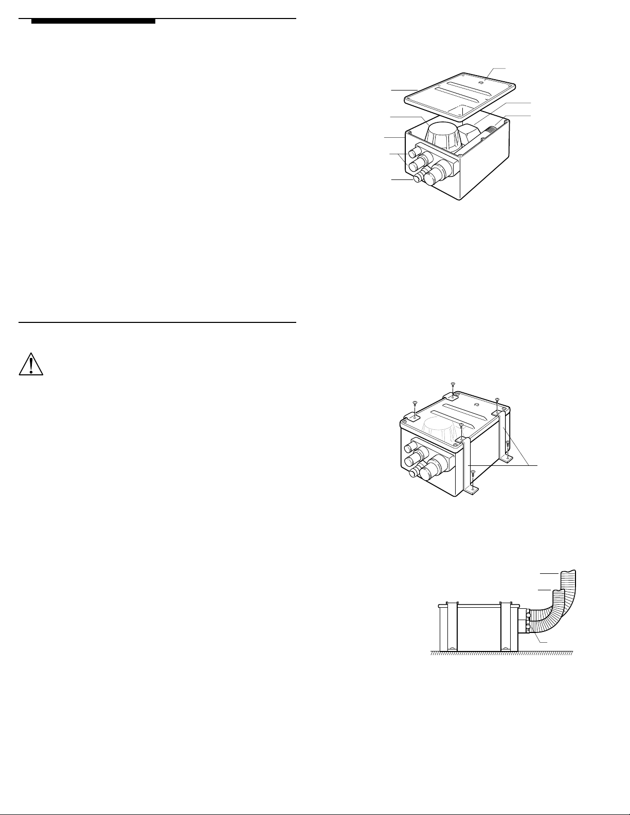
Cover
Optional 1/4" Vent
Hole Location
Float Switch
FilterPump
Box
Inlets
Outlet
•
•
•
•
•
•
•
•
•
3
Deluxe Shower Sump System
4137, 4138 Mounting Instructions
Attwood marine hardware, navigational lighting, bilge pumps, and other
marine accessories are specified more than any other brand by America’s
best-known boat manufacturers as original equipment. Look to Attwood
for quality replacement parts and marine accessories.
SAVE THESE INSTRUCTIONS
Form Number 69274 Rev. K 98-08
2. For hook-up to multiple inlets/hose sizes, determine opening sizes needed
and saw ends off the correct fittings (sizes and cut locations are marked
on the fittings). File around the fitting inside diameter to remove burrs and
rough edges. Figure 1
Figure 1
The Attwood Deluxe Shower Sump System is an efficient, low cost system
incorporating an Attwood 750 GPH Pump and an Attwood Automatic Float
Switch. This system is designed to satisfy the needs of the boater for a
functional means of transferring “gray” water from the shower, or other
water drains. Multiple inlets can be hooked up to more than one drain with
different hose size options. The see-through top on the box allows you to
see when the filter needs cleaning.
Refer to the chart below to ensure that you have selected the proper shower
sump for your boat application:
Shower Sump D.C. Voltage D.C. Amps Max Fuse
Model Amperages
4137 12.0 2.7 4
4138 24.0 1.8 2
WARNING:
To prevent personal injury, never use 120/240 VAC power tools while
working in water or a wet environment.
To prevent personal injury, always disconnect the power source before
servicing or installing this product.
Always use the fuse amperage rating specified for this shower sump model.
Failure to do so could result in serious personal injury or fire hazards.
To prevent possible injury and water damage, shut off all water before servicing.
REQUIRED FOR INSTALLATION
• Fine-tooth hacksaw or
band saw
• File
• Drill and suitable drill bit
• Four #8 screws for
hold-down clamps
Optional:
• Attwood model 7615 switch or equivalent
Note:
Switch is recommended to allow the pump to be turned off in
an emergency
The following materials are needed if no sump pump mounting pad is in place:
• 1/2" (1.27) thick marine plywood
block large enough to mount
sump pump
• Hand-held roller
INSTALLATION INSTRUCTIONS
1. Determine location of sump system, making sure system is lower than the
shower drain. Ensure there is enough structure and room to accommodate the sump system before drilling.
Note:
For correct operation of the automatic float switch, the box should be
mounted level. If the box cannot be mounted level, the end without fittings
can be raised up to 1/2" from level.
Note:
Because sailboats tend to heel, install sump system parallel lengthwise
with the bow-to-stern line. Fitting end can face either fore or aft.
• Phillips screwdriver
• One hose clamp for each
hose used
• Wire connectors for
16-gauge wire
• See amperage in chart above
• Fiberglass—18 oz. mat or woven
roving
• Polyester resin and catalyst
3. To install mounting pad:
Locate mounting pad area according to guidelines in Step 1.
4. Sand gelcoat or paint off the mounting surface to create an area that
is 3" wider than the mounting pad on each side.
Completely cover the mounting pad with fiberglass. Saturate the
fiberglass with resin, and press the fiberglass edges down against
the hull to adhere the pad in place. Roll out the fiberglass to remove
any uneven surfaces, air bubbles, or excess resin.
5. Place the box in desired location. Position the hold-down clamps (two
on each side) so the top of the clamps are between the two raised ribs.
Figure 2
Mark the screw hole locations and drill the pilot holes.
the hull!
Note:
If possible, pre-wire the sump system before fastening clamps down. See
wiring diagram. Figure 4
Figure 2
•
•
6. Connect 3/4" I.D. outlet hose from thru-hull connector to the outlet fitting.
Secure the connection with a hose clamp.
Note:
The outlet hose must rise smoothly from the fitting, up to the thru-hull.
Any downward dip will trap water and air inside the pump. Figure 3
Figure 3
For correct operation, outlet
hose must continually rise
above pump outlet to
prevent air-lock
Inlet Hose(s)
Outlet Hose
Do not drill through
Hold-Down Clamps
•
•
•
Hose Clamp
7. Connect inlet hoses from the drains to the inlet fittings. Secure each
connection with a hose clamp.
Note:
The inlet hoses must rise smoothly from the fitting, up to their Drains.
Also, using a shower drain with a trap will not allow air to vent out of the
box, and the rising water will not activate the float switch.
If the hose cannot be routed upward, or a drain with trap is desired:
Vent the sump system box by removing the system cover and drilling a 1/
4" hole where indicated. File away any rough edges, and replace the
cover (position hole toward the box end with no fittings). See Figure 1
8. Fasten sump system in place with the four hold-down clamps and four screws.
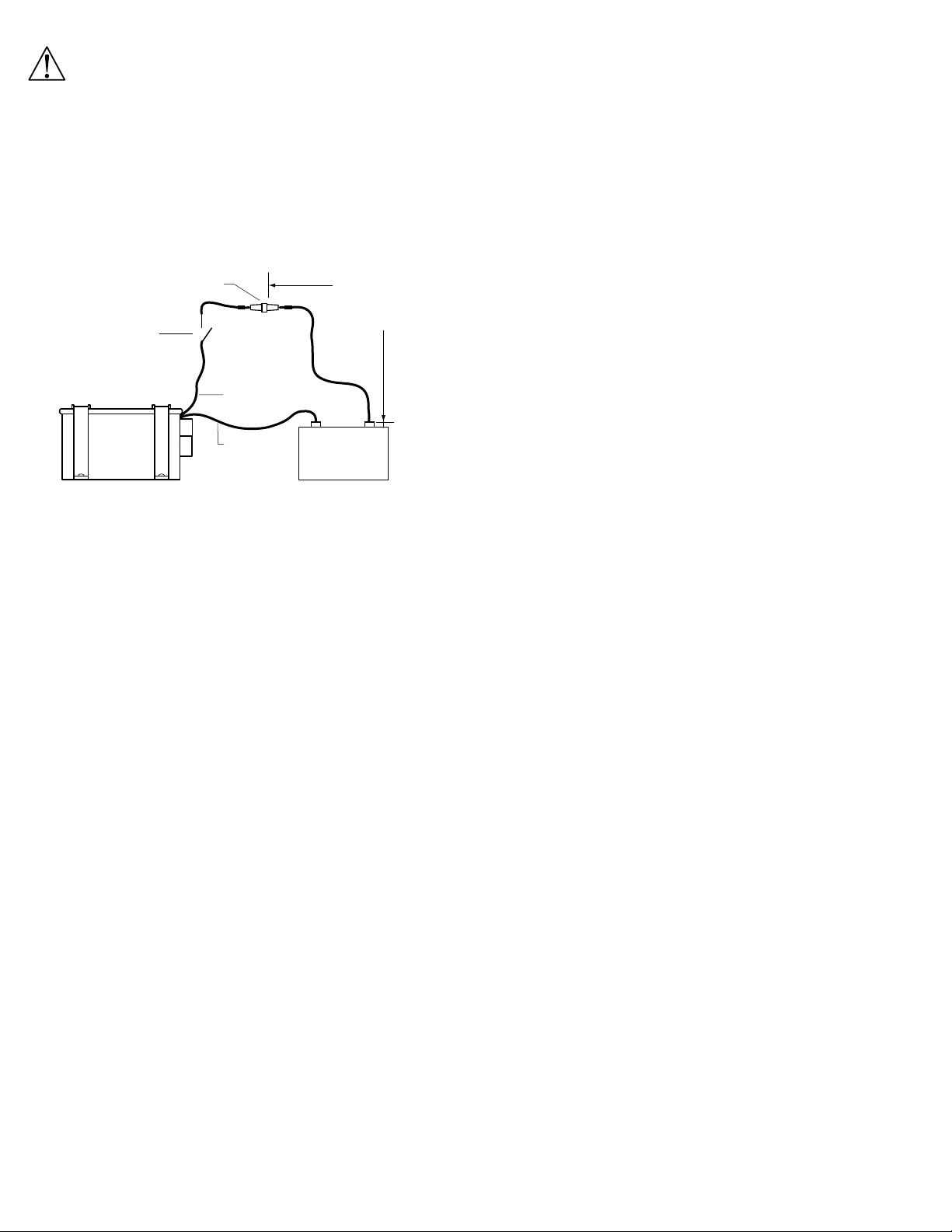
WIRING INSTRUCTIONS
WARNING:
Model 4137: Use 12-volt DC power source. Model 4138: Use 24-volt DC
power source. Higher DC voltage or AC voltage may cause serious damage
and/or personal injury.
Circuit must be properly fused to prevent possible fire hazard and/or damage
to pump and switch should the pump become jammed.
Caution:
All connections should be made using crimp-on connectors.
1. Electrical connections should be made as shown in Figure 4.
Figure 4
4-Amp. Model 4137
2-Amp. Model 4138
Two-Terminal, “On-Off” Type
Switch Can Be Attwood
Rocker, Push-Pull, or
Toggle Type
Sump System
•
•
•
•
Brown Wire
•
Black Wire
•
72" (183 cm)
Maximum Length
From (+) Terminal
to Fuse Holder
–
DC Battery
+
Problem Probable Cause
Pump will not turn off • System improperly wired
• Float switch is jammed in
“on” position
• Box not mounted level
• Air is trapped in box—cover
needs to be vented
Pump output is low • System wired backwards
• Line is plugged/restricted
System leaking at top • Air is trapped in box—cover
System is leaking at
inlet/outlet connection
Pump turns on but does not pump • Line is plugged
Water returns to sump from
outlet hose
needs to be vented
• Hose clamp is missing
• Hose clamp is loose
• Pipe connection is loose
• Outlet hose does not rise
continuously to thru-hull
• Check value plugged
or damaged
12-Volt DC Model 4137
24-Volt DC Model 4138
2. Using butt connectors for 16-gauge wire, splice fuse holder into positive
lead (brown) in a location easily accessible for changing fuses. Install
the specified fuse.
3. Run brown wire from sump system directly to the positive (+) battery
terminal. If using manual on/off switch, run brown wire from sump system
to the switch, then to the positive (+) battery terminal.
4. Connect black wire from the sump pump system to the negative (-)
battery terminal to complete the circuit.
5. Re-connect power and water, and test unit for proper installation.
Feed water into the sump; if the flow appears to be too low, check
wire connections.
Note:
Reversed connections will result in opposite impeller rotation, which
drastically reduces capacity and can cause premature pump failure.
MAINTENANCE INSTRUCTIONS
Drain the unit during the winter months when not in use. Disconnect and
drain all lines to the unit. Remove hold-down clamps and empty the unit.
In some installations, it may be impossible to completely drain the system.
Add a non-toxic RV/marine antifreeze to the shower drain and circulate it
throughout the system.
For improved performance, periodically clean the filter. Remove the
cover and slip the filter out for easy cleaning. Re-install the filter and
cover when finished.
TROUBLE SHOOTING
Problem Probable Cause
Pump will not turn on • Line is plugged
• Line is broken
• No power to the pump
• Fuse is blown
• System improperly wired
• Manual switch is not turned on
• Air is trapped in box—cover
needs to be vented
• Float Switch is jammed in
“off” position
ATTWOOD LIMITED WARRANTY
ATTWOOD CORPORATION, 1016 North Monroe, Lowell, Michigan 49331
(“Attwood”) warrants to the original consumer purchaser that Attwood brand
products will be free from defects in materials and workmanship under normal
use and service for one year from the date of original consumer purchases.
This limited warranty is not applicable if the product has been damaged by
accident, improper installation, unreasonable or improper use, lack of proper
maintenance, unauthorized repairs or modifications, normal wear and tear,
or other causes not arising out of defects in materials or workmanship.
Attwood products are warranted for use on pleasure boats. Any other
use — including but not limited to commercial, racing, or non-marine
use — are not covered under this warranty. Attwood’s obligation under this
warranty is limited to repair of the product at Attwood’s plant or replacement
of the products at Attwood’s option without expense to the original consumer
purchaser. Any expenses involved in the removal, reinstallation or transportation
of the product are not covered by this warranty.
The product must be returned to Attwood’s plant at the address above,
postage prepaid, and insured with proof of original purchase including date.
If Attwood is unable to replace the product and repair is not commercially
practical or cannot be timely made, or if the original consumer purchaser is
willing to accept a refund in lieu of repair or replacement, Attwood may refund
the purchase price, less an amount for depreciation. The acceptance by
Attwood of any product returned or any refund provided by Attwood shall not
be deemed an admission that the product is defective or in violation of any
warranty. Products that are replaced or for which a refund is issued become
the property of Attwood.
THIS WARRANTY IS ATTWOOD’S ONLY EXPRESS WARRANTY OF
THIS PRODUCT. NO IMPLIED WARRANTY SHALL EXTEND BEYOND
ONE (1) YEAR FROM THE DATE OF ORIGINAL CONSUMER PURCHASE.
ATTWOOD SHALL NOT BE LIABLE FOR ANY DAMAGES FOR LOSS OF
USE OF THIS PRODUCT, NOR FOR ANY OTHER INCIDENTAL OR
CONSEQUENTIAL DAMAGES, COSTS OR EXPENSES.
Some states do not allow limitations on how long an implied warranty lasts
or the exclusion or limitation of incidental or consequential damages, so the
above limitations and exclusions may not apply to you. This warranty gives
you specific legal rights, and you may have other rights which vary from
state to state.
© 1998
Attwood
Subsidiary Steelcase Inc.
1016 N. Monroe Street, Lowell, MI 49331-0260
 Loading...