

Page 1

ATTO Technology, Inc.
155 CrossPoint Parkway
Amherst, New York 14068 USA
www.attotech.com
Tel (716) 691-1999
Fax (716) 691-9353
Sales support: sls@attotech.com
Technical support: Monday -- Friday, 8am-6pm EST
techsupp@attotech.com (716)691-1999 ext. 242
© 2014 ATTO Technology, Inc. All rights reserved. All brand or product names are trademarks of their respective holders.
No part of this document may be reproduced in any form or by any means without the express written permission of ATTO
Technology, Inc.
09/2014 PRMA-0465-000MD
FibreBridge™ 7500
Getting Started Guide
Thank you for purchasing an ATTO FibreBridge. This guide gives you the basics for installing
and configuring your FibreBridge. For more information, refer to the FibreBridge Installation
and Operation Manual located at attotech.com/downloads
Examine the contents of your FibreBridge
packing box. If any of the items listed below
are missing, contact your ATTO
representative.
• The FibreBridge. Note the serial number of
your FibreBridge unit:
________________________
• Power cords
• “L” brackets for mounting in a 19” rack
• Ethernet cable
• RS 232 cable
1 Install the FibreBridge
1.1 Place the FibreBridge on a stable flat
surface, install it into a standard rack
or into your device.
If installing the FibreBridge 7500
into a rack, see Exhibit 1 and follow
these instructions:
a. Attach “L” brackets so that the
front side with the LEDs face front
and the connector side is at the
back.
b. Install the FibreBridge horizontally
within the rack so it does not reduce
the air flow within the rack.
1.2 Connect and power up Fibre Channel
devices from your SAN to the
FibreBridge using SFPs and multimode
fiber optic cables for the Fibre Channel
ports. Keep cable lengths as short as
possible to ensure the highest signal
quality and performance. Refer to
Cabling in the FibreBridge Installation
and Operation Manual.
1.3 Connect and power up SAS/SATA target
devices. Refer to Cabling in the
FibreBridge Installation and Operation
Manual.
1.4 Connect the Ethernet port to your
network.
1.5 Connect power:
a. Connect the AC power cords from the
FibreBridge to the proper AC source
outlets.
Power is automatically supplied to the 7500 when plugged
into an AC outlet.
Note
The power source must be connected to a protective
earth ground and comply with local electrical codes.
Improper grounding may result in an electrical shock
or damage to the unit.
If you are using a rack:
a. Properly ground the FibreBridge to the
rack equipment. The earth ground
connection must be maintained.
Page 2
b. The power requirements plus the power
draw of the other equipment in the rack
must not overload the supply circuit and/
or wiring of the rack.
1.6 Wait up to two minutes for the FibreBridge
Ready LED to light indicating the
FibreBridge has completed its power-on
self test sequence.
2 Discover the IP address
Note
The FibreBridge is initially configured with DHCP
enabled. It is best if you have access to a DHCP server.
2.1 Work from the computer attached to the
FibreBridge Ethernet port on the same
domain.
Note
To find the IP address you need the ATTO QuickNAV
TM
tool.
.
Go to attotech.com/downloads, sign in or register for an
account, then select FibreBridge 7500 on the Downloads page
to download QuickNAV.
2.2 Install QuickNAV and launch the program
to identify the FibreBridge.
2.3 Locate the FibreBridge with the serial
number recorded earlier.
2.4 Highlight the serial number.
2.5 Click Next.
If a DHCP server is available on your network,
an address is assigned automatically by the
server. Note the assigned address:
____________________________________
If you do not have a DHCP server, get an IP
address and subnet mask from your network
administrator, type it into the area provided,
and click on Next.
2.6 Click on Launch Browser
Your browser points to the ATTO
ExpressNAV splash screen. If you use
Internet Explorer as a browser, continue on to
Internet Explorer setup below. If not, continue
on to Begin initial configuration .
3 Internet Explorer setup
3.1 Open your browser
3.2 Select Internet Options.
3.3 In the Internet Options screen, select the
Security tab.
3.4 Click on the Trusted Sites icon.
3.5 Click on the Sites button.
3.6 In the text box Add this Web site to the
zone, add the IP address of the appliance.
You may use wild cards.
3.7 Click on Add
3.8 Uncheck the Require server verification
check box.
3.9 Click OK.
3.10 At the bottom of the Internet Options box,
click on OK and close the box.
4 Using FTP
4.1 Establish an FTP link to the bridge that is to
be flashed.
Note
The FibreBridge does not support passive mode. The FTP
connection must be set up for both active mode and binary
mode for the transfer to complete.
4.2 Use the PUT command to download the
firmware file to the bridge. For example:
PUT c:\bridge_firmware\at750100.zbd
4.3 Once the download is complete, cycle
power on the FibreBridge to implement the
new firmware.
5 Begin initial configuration
5.1 The ExpressNAV System Manager
welcome screen appears. Click on Enter
Here
5.2 Type in the user name and password.
Note
The default values are user name
root
and password
Password
. The user name is case insensitive and the
password is case sensitive.It is best practice to change
the default user name and password.
5.3 You are now ready to configure the
FibreBridge for use. For more information,
refer to the Installation and Operation
Manual.
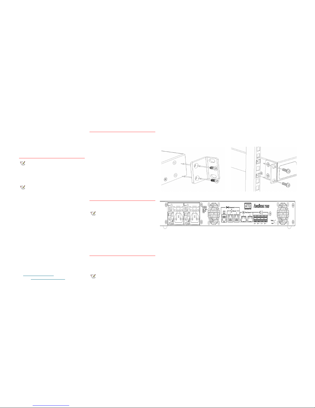
Exhibit 1 Brackets to install the FibreBridge into a rack
Exhibit 2 FibreBridge 7500D, LEDs, power receptacle
and ports
 Loading...