

ATTO Technology FibreBridge 6500N Installation And Operation Manual

ATTO FibreBridge
™
Installation and Operation Manual
ATTO FibreBridge 6500N
8-Gigabit Fibre Channel to 6-Gigabit SAS bridge

ATTO Technology, Inc.
155 CrossPoint Parkway
Amherst, New York 14068 USA
www.attotech.com
©
2012 ATTO Technology, Inc. All rights reserved. All brand or product names are trademarks of their respective
holders. No part of this manual may be reproduced in any form or by any means without the express written
permission of ATTO Technology, Inc.
2/2012
........................................................................................................................................................
PRMA-0402-000

Contents
1.0 ATTO FibreBridge Overview .........................................................................1
ATTO FibreBridge 6500N features, benefits
1.1 ATTO FibreBridge 6500N ....................................................................2
Dimensions
Cooling and airflow
Power
Fibre Channel ports
SAS ports
Management ports
LED indicators
2.0 Install the FibreBridge ...................................................................................4
Unpack the packing box; verify contents
Install the FibreBridge
Configure an Ethernet Management Port
Internet Explorer setup
3.0 Configure the FibreBridge ............................................................................6
Preliminary steps
Port configurations
Modify passwords
Time & Date
4.0 Interface options ............................................................................................8
Using ExpressNAV System Manager
Opening an ExpressNAV session
Optimizing ExpressNAV in Internet Explorer
Using the serial port
Using Telnet
5.0 Update Firmware ............................................................................................10
Using ExpressNAV
Using FTP
Using the zModem command
Appendix A Cabling ..............................................................................................i
Serial port connections
Ethernet connections
Appendix B CLI provides ASCII-based Interface ...............................................ii
CLI error messages
CLI summary reference
Command explanations

Appendix C Standards and Compliances ...........................................................ix
Regulatory Notices
FCC Notices (US only)
Compliance with ICES-003
Compliance with EN Regulations
Bureau of Standards, Metrology, and Inspections Notice (BSMI, Taiwan Only)
Voluntary Control Council for Interference by Information Technology Equipment (VCCI, Japan)
Japan Electronics and Information Technology Industries Association (JEITA) Power Cable
Statement
Compliance Statement, Korea
Appendix D Warranty Information .......................................................................xi
Manufacturer limited warranty
1.0 ATTO FibreBridge Overview
The ATTO FibreBridge™ is a performance tuned intelligent protocol translator which allows upstream initiators
connected via Fibre Channel to communicate with downstream targets connected via SAS. FibreBridge products
are fitted for rack mount integration.
Fibre Channel is a serial communications technology
designed to transfer large amounts of data between a
variety of hardware systems over long distances. It is
a key technology for applications that require shared,
high bandwidth access to storage.
Fibre Channel provides a logical point-to-point serial
channel for the transfer of data between a buffer at a
source device and a buffer at a destination device. It
moves buffer contents from one port to another,
without regard to the format or meaning of the data, so
different upper level protocols are able to run over
Fibre Channel hardware.
Serial Attached SCSI (SAS) is an industry standard
specification whose architecture consists of a multilayer definition including three transport protocols for
supporting initiator communication with end-point
ATTO FibreBridge 6500N features, benefits
devices and SAS expanders. The SAS connection
model enables aggregation of physical links forming a
logical point-to-point serial channel for transfer of data
between SAS initiators and target end-point devices.
The physical layer supports data rates of 3 and 6
Gbps.
The ATTO FibreBridge 6500N bridges upstream
initiators connected via FC to downstream end-point
devices connected via SAS. On the upstream side,
direct attachment to vendor specified host system FC
HBAs and fabric attachment to vendor specified FC
switches are supported. On the downstream side, the
FibreBridge 6500N supports vendor specified disk
shelves attached via the SAS interface.
.
The ATTO FibreBridge 6500N is an 8-Gigibit Fibre
Channel to 6-Gigibit SAS bridge.
The FibreBridge 6500N is a customized version of
ATTO’s standard Fibre Channel to SAS bridge.
• Two independent 8Gb Fibre Channel ports
which auto-negotiate to 2Gb, 4Gb or 8Gb Fibre
Channel
• SFP+ FC connectors included
• 6Gb QSFP connector which auto-negotiates to
3Gb or 6Gb
• ExpressNAV
configuration, management and diagnostic
capabilities
• Supports SAS expanders
™
System Manager for remote
1

1.1 ATTO FibreBridge 6500N
CAUTIONCAUTION
Note
Note
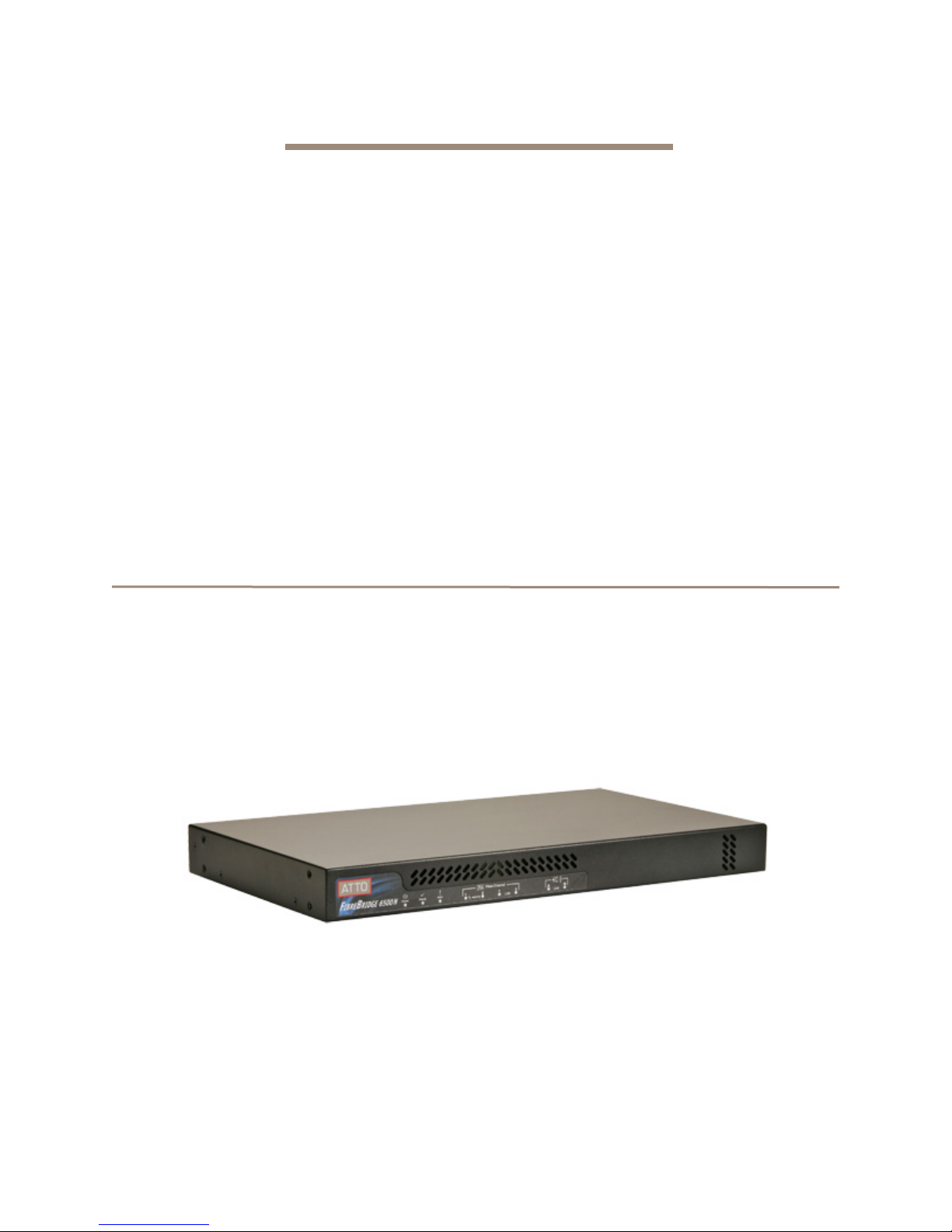
The ATTO FibreBridge 6500N is a high performance bridge which adds 8-Gigabit Fibre Channel connectivity to
6-Gigabit SAS storage devices.
The FibreBridge 6500N is available in an industrystandard 1U form factor for easy integration into racks
and cabinets.
Dimensions
Width:
Rackmount units have mounting hardware that will
extend the width to fit a 19" rack.
Length:
Height:
Weight:
(unboxed), 12.4 pounds (boxed).
17.31 inches
9.90 inches
1.69 inches (1U)
Rackmount units weigh 8.75 pounds
Cooling and airflow
Operating temperature:
BTU:
205 BTU per hour
Humidity:
Airflow:
Air enters from the front and is exhausted out the rear
(connector side). Ambient air near the inlets should not
exceed 40°C. The unit automatically stops operation if
the temperature goes beyond this threshold.
10-90% non-condensing
150 LFM
Do not block the enclosure’s vents. The
FibreBridge does not allow data transfer if
overheating occurs.
5-40 °C external; 10,000 ft.
Fibre Channel ports
The dual independent 8Gb/s Fibre Channel ports
connect the FibreBridge 6500N to Fibre Channel hosts
using optical SFP+ connectors and multimode fiber
optic cable. Make sure all cables are anchored
securely at both ends with the proper connectors.
SAS ports
Two (x4) wide 6Gb/s capable SAS connectors are
present on the 6500N however only the 'A' labelled
connector may be used to connect disk shelves.
Shelves/devices connected to the 'B' port will not be
recognized by the bridge.
Management ports
Management is provided using the dual 100/1000
base T Ethernet ports accessible from two right angle
RJ-45 connectors, or the RS-232 serial header
console port accessible from the serial RJ-45
connector.
Ethernet ports 1 & 2 are functionally equivalent
and connection to at least one is
recommended.
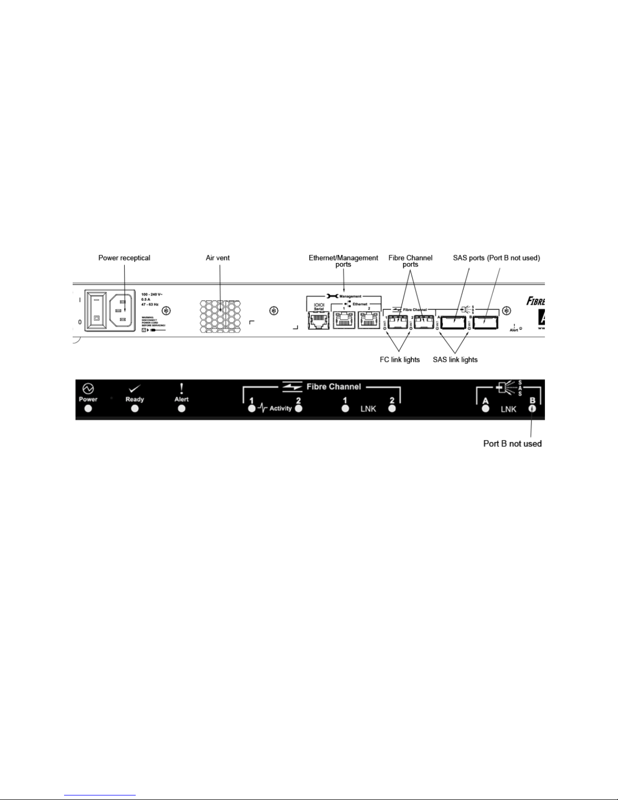
LED indicators
The LED indicators can be viewed from the connector
side and the front side of the FibreBridge 6500N.
Thermal monitoring of the bridge available.
Power
The power supply circuit is permanently mounted
within the enclosure and is not hot swappable. It has
one standard IEC320 power receptacle and switch.
The universal power supply provides power for the
bridge board and cooling fan.
The power requirements of the ATTO FibreBridge
6500N plus the power draw of the other equipment in
the rack must not overload the supply circuit and/or
wiring of the rack.
Input voltage:
Power Consumption:
Power Consumption:
2
ATTO Technology Inc. FibreBridge Installation and Operation Manual
85-264 VAC; .5A; 47/63Hz.
0.5A for 110V (55 watts)
0.25A for 220V (55 watts)
LEDs on the connector side are:
Yellow Alert LED:
status, and is off when the bridge is not faulted
Ethernet port connectors:
the upper right of each Ethernet port connector
indicates Link/Activity, where green solid indicates
link, blinking indicates activity and off means no link is
present. There is also a green LED located to the
upper left of the Ethernet connectors that indicates
100/1000 MbE speed as follows: green steady
indicates 100MbE and off indicates 1000MbE.
Fibre Channel port:
link, and off means no link.
lights yellow to indicate Faulted
a green LED located to
A lighted green LED indicates
SAS device:
indicates a link has been established on at least one
PHY, and off means there are no links or the port is
disabled (SAS port B LED will always be off).
A lighted green LED on each connector
Fibre Channel port:
two discrete LEDs per port
indicate activity and link. The first green LED of each
port indicates activity, where on means there is activity
and off means no activity on the port. The second
green FC port LED indicates link, where a lighted
LEDs on the faceplate are:
Power:
A lighted green LED indicates power has been
turned on to the bridge.
A Ready LED
is lighted green to indicate ready and off
to show not ready.
An Alert LED
is lighted yellow to show an alert
green LED indicates link and off means no link.
SAS device:
A lighted green LED for each SAS
connector indicates a link has been established on at
least one PHY in the connector, and off means there
are no links or the port is disabled (SAS port B LED will
always be off).
condition.
Exhibit 1.1-1 Connectors, LEDs and power receptacle on the connector side and LEDs on the faceplate.
3
2.0 Install the FibreBridge
CAUTIONCAUTION
Note
Note
CAUTIONCAUTION
Use the following instructions to install the FibreBridge.
Unpack the packing box; verify contents
• The FibreBridge. Note the serial number of your
FibreBridge unit: ________________________
• “L” brackets for mounting in a 19” rack
(pre-installed)
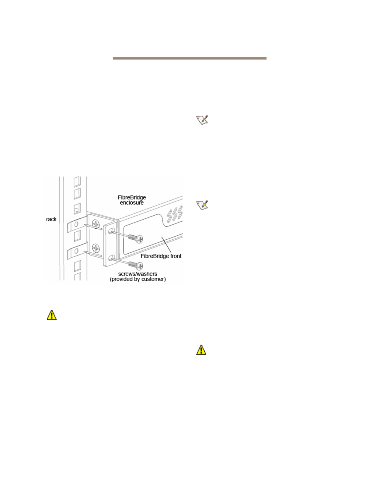
Install the FibreBridge
1 Mount the FibreBridge into a standard 19” rack
or cabinet ensuring air flow through the unit is
unobstructed. Mount horizontally only.
Exhibit 2.0-1 Install the FibreBridge 6500N into a
rack or
2 Refer to cabling and power-up sequencing
cabinet.
provided by the Storage Solutions vendor.
The power source must be connected to a
protective earth ground and comply with
local electrical codes. Improper grounding
may result in an electrical shock or damage
to the unit.
a. Properly ground the FibreBridge to the rack
equipment. The earth ground connection
must be maintained.
b. The power requirements plus the power
draw of the other equipment in the rack
must not overload the supply circuit and/or
wiring of the rack.
Configure an Ethernet Management Port
The FibreBridge is initially configured with
DHCP enabled. It is best if you have access to
a DHCP server. If you do not have a DHCP
server, get an IP address, subnet mask and
Gateway IP address from your network
administrator.
1 To configure an Ethernet Management Port
using the Command Line Interface (CLI) and
the serial port connection, skip to step 9.
When connecting to a Management Port
(Ethernet 1 or 2), in the absence of network
connectivity an Ethernet cable can be used to
connect the Ethernet port directly to a laptop or
other computer.
2 The proper QuickNAV utility must be
downloaded and resident on the setup
computer before configuring the FibreBridge.
Download either QuickNAV-windows.exe for
Windows or QuickNAV-Mac for Mac OS X,
depending on your operating system. The
QuickNAV utility must be at version 3.3 or later.
3 Work from the computer attached to the
FibreBridge Ethernet port on the same
broadcast domain. Run the QuickNav Utility
QuickNAV-windows.exe for Windows or
QuickNAV-Mac for Mac OS X.
Active VPN clients on the setup computer
will cause QuickNAV to fail and not find the
FibreBridge. VPN must be shutdown
before using the QuickNAV utility.
4 Locate the FibreBridge with the serial number
recorded earlier.
5 Highlight the serial number.
4
ATTO Technology Inc. FibreBridge Installation and Operation Manual
 Loading...