

ATTO Technology FibreBridge 1190E Installation And Operation Manual

ATTO Technology, Inc.
ATTO
TM
FibreBridge
TM
1190E
Installation and Operation Manual
© 2001 ATTO Technology, Inc. All rights reserved. All brand or product names are trademarks of their respective
holders. No part of this manual may be reproduced in any form or by any means without the express written
permission of ATTO Technology, Inc.
8/2001 Document Control Number: PRMA-0268-000


Table of Contents
Chapter 1
Fibre Channel is a key technology for storage ...................................1
Chapter 2
ATTO FibreBridge supports diverse SAN needs ................................3
Chapter 3
ATTO FibreBridge 1190E characteristics ............................................5
Chapter 4
How to connect SCSI devices to SCSI ports .......................................7
Chapter 5
How to connect the Fibre Channel port ...............................................8
Chapter 6
ATTO FibreBridge addressing ..............................................................9
Chapter 7
How to access ATTO FibreBridge Services ........................................11
Chapter 7.1
Command Line Interface use and guidance .............................13
Chapter 7.1.1
General use commands ...................................................15
FibreBridgeName
Info
Help
Reserve
RestoreConfiguration
SaveConfiguration
VerboseMode
Chapter 7.1.2
Mapping commands .........................................................16
AutoMap
DispFcPortDB
FcHard
FcHardAddress
FibreBridgeTargetLUN
RouteChange
RouteDisplay
RouteOffline
RouteOnline

Chapter 7.1.3
Diagnostic commands .....................................................19
ClearEvent
DispEvent
DisplayEvent
EccLog
ErrorLog
IdentifyFibreBridge
LogEvent
ParityLog
Performance
Chapter 7.1.4
SCSI configuration commands .......................................21
ScsiInitID
ScsiPortBusSpeed
ScsiPortList
ScsiPortResetOnStartup
ScsiPortSelTimeout
ScsiPortSyncTransfer
ScsiPortTaggedQueuing
ScsiPortUltra2
ScsiPortWideTransfer
ScsiTargets
ScsiTermination
Chapter 7.1.5
Fibre Channel configuration commands .......................23
FcAck0
FcClass2
FcConnMode
FcFairArb
FcFrameLength
FcFullDuplex
FcInitiator
FcPortList
FcSCSIBusyStatus
FcTargets
FcWWName
FibreBridgeTargetLUN
Chapter 7.1.6
Serial Port configuration commands .............................25
SerialPortBaudRate
SerialPortEcho
SerialPortHandshake
SerialPortStopBits
Chapter 7.1.7
Ethernet configuration commands .................................26
EthernetSpeed
IPAddress
IPDHCP
IPGateway
IPSubnetMask

Chapter 7.1.8
Maintenance commands ..................................................27
FibreBridgeModel
FirmwareRestart
SerialNumber
MaxEnclTempAlrm
MinEnclTempAlrm
ScsiPortReset
Temperature
Zmodem
Chapter 7.2
In-band CLI using SCSI over Fibre Channel port .....................29
Chapter 8
Serverless backup support ...................................................................31
Chapter 9
Updating firmware .................................................................................33
Index
Command Line Interface commands....................... ......... i
Appendix A
Examples of command usage ............................. ..........iii
Appendix B
Standards and compliances ................................ ..........vii
Appendix C
Fibre Channel Accessories .................................. ..........ix
Appendix D
How to Contact ATTO Technology, Inc. .............. ..........xi

1 Fibre Channel is a key technology for storage
Fibre Channel is a serial communications technology designed to transfer large amounts of data
between a variety of hardware systems over long distances. It is a key technology for applications that
require shared, high bandwidth access to storage.
Fibre Channel provides a logical point-to point
serial channel for the transfer of data between a
buffer at a source device and a buffer at a
destination device. It moves buffer contents from
one port to another, without regard to the format
or meaning of the data, so different upper level
protocols are able to run over Fibre Channel
hardware.
The Fibre Channel architecture is structured as a
hierarchica l set of pro tocol laye rs. Def ined with in
these layers are rules for signal interfaces, serial
encoding and decoding, error control, frame
format and communications protocols.
All A TTOTM FibreBridgeTM models can be used in
A SAN is a shared storage architecture connecting
computers and storage devices for online data
access. Each connected system can directly access
any attached storage device. Storage devices
could include RA ID , ta pe ba c k up , tape libr a ry,
CD-ROM library or JBOD.
SANs maintain greater fault tolerance and load
balancing by supporting server clustering and
failover (the ability for one server to take over for
another in the event of a failure).
ATTO FibreBridge models provide the interface
between SCSI and Fibre Channel resources in
SANs. Possible configurations depend upon your
current hardware and what you need to do.
a SAN (Storage Area Network) to connect a
variety of Fibre Channel and SCSI devices to
meet your needs.
Glossary
Some terms used in the Fibre Channel industry are defined below . More information is available through
the F ibre C hannel Industry Assoc iation
Association
(www.snia.org)
and the Fibre Channel Consortium
(www.fibrechannel.com)
, the Storage Area Networking Industry
(www.iol.unh.edu)
.
Term Definition
fabric A Fibre Channel s witch or two or m ore Fibre Channe l s witche s interconnec ted to
physically transmit data between any two N_Ports on a switch or switches.
failover The substitution of a working system for one which has failed.
FC-AL Fibre Channel Arbitrated Loop: A Fibre Channel network in which up to 126
systems and devices are connected in a loop topology, with each transmitter
connecting to the receiver of the device to its logical right. The Fibre Channel
Arbitrated Loop protocol used for transmission is different from Fibre Channel
switche d and point to point prot ocols. Multiple FC-A L loops can be conn ected via
a fabric switch to extend the network.
firmware Software stored in read-only memory (ROM) or programmable ROM (PROM).
Firmware is often resp onsible f or the beha vior of a sy stem when it is fi rst switc hed
on.
AT TO Technology FibreBridge 1190E Installation and Operation Manual
1

Term Definition
F_port A port in the Fibre Channel fabric where a N_port may attach
FL-port A port in the Fibre Channel fabric where a NL_port may attach in an arbitrated
loop
hot swapping Components are removed and replaced while the unit is running, with power to
either the component or a device connected to the unit. Not all components are
hot swappable: please read installation and maintenance instructions carefully.
initiator device A component which originates a command
JBOD Just a Bunch Of Disks: a storage subsystem using multiple independent disk
drives with or without RAID configuration.
LED Light-emitting diode , a type of dio de that emits li ght when current pas ses through
it. Visible LEDs are used as indicator lights on all sorts of electronic devices.
LUN Logical Unit Number: a SCSI or Fibre Ch annel identifier of a device
NL port a port attached to a node in Fibre Channel arbitrated loop or fabric loop
configurations
N_port a port attached to a node used with point to point or fabric configurations
RAID Originally Redundant Array of Inexpensive Disks, now Redundant Array of
Independent Drives: a storage system spanning multiple disk drives.
The following standard RAID specifications will be used here:
Glossary
RAID 0: disk striping in which fixed-length sequences of data are mapped to
member disks in a regular rotating pattern.
RAID 1: Mirrored arr ays: inf ormation written to on e disk is a lso written to ano ther
simultaneously. Also known as disk shadowing, real-time copy, and t1 copy.
RAID 10: Striped array with mirroring
SCSI Small Computer Systems Interface: a processor-independent standard for
system-le v el interf ac e betw een a compute r and in telligent d e vices i ncluding hard
disks, floppy disks, CD-ROM, printers, scanners, etc.
topology logical layout of the parts of a computer system or network and their
interconnections
2

2 ATTO FibreBridge supports diverse SAN needs
The ATTO FibreBridge
TM
family of products provides a Fibre Channel-to-SCSI bridg e av ail ab le as a
embedded boa rd , a stand alone e nclosur e that c an be fitted for rac kmount int e gration, o r a desktop unit ,
depending on the model and your needs.
The ATTO FibreBridge family of products share
common configuration options and functions to
provide the most versatile connectivity options
available. Each product has been engineered to
address specific customer needs. New capabilities
are integrated into products throughout the
have the most up-to-date version of the firmware,
visit the ATTO Technology website,
www.attotech.com.
All A TTO FibreBridge models include full duplex
mode, Class 2 transfers, Intermix transfers and
direct fabric connect capabilities.
FibreBridge family as much as possible, requiring
only an upgrade of firmware to incorporate them
into your SAN (see Chapter 9). To make sure you
Please refer to the Technical Specifications for
complete information about your FibreBridge
model.
Quick start instructions for the FibreBridge 1190E
The ATTO FibreBridge 1190E offers a variety
of ways to connect into a SAN. The following is
a quick start description:
1 Place the FibreBridge 1190E where you
want it. (See Chapter 3)
2 Connect the SCSI devices to the
FibreBridge . (See Chap ter 4)
3 Connect the FibreBridge to your SAN:
attach short wave optical cables into the
Fibre Channel port on the FibreBridge. (See
Chapter 5)
4 Connect to the management (services) port
via the RS-232 serial port or Ethernet. (See
Chapter 7)
5 Map your devices to the appropriate
FibreBridge Fibre Channel port. (See
Chapter 6 and Chapter 7.1.2)
6 Boot the computers on the SAN and
configure the devices connected to the
FibreBridge.
AT TO Technology FibreBridge 1190E Installation and Operation Manual
3

Exhibit 2-1 The following chart provides an overview of the features and capabilities for the newest FibreBridge
models. Contact your authorized ATTO representative or visit ATTO Technology’s website, www.attotech.com, for
additional information.
Introduction
ATTO FibreBridgeTM feature availability matrix
1180E 1190E 2200R/D 3200R 4500C/R/D
FC Ports 1 1113
FC port number
0
0000, 1, 2
(fp)
FC interface DB9/SC
DB9/SC GBIC GBIC SC
Data transfer 1 Gigabit 1 Gigabit 1 Gigab it 1 Gi gab it 1 Gi gab it
SCSI ports 1
SCSI bus number
0
2224
0, 1 0, 1 0, 1 0, 1, 2, 3
(sb)
Maximum data
80 MB/sec.
100 MB/sec. 100 MB/sec. 100 MB/sec. 300 MB/sec.
transfer rate
Configuration Board
(embedded)
Error checking &
Yes
Board
(embedded)
Yes No No Yes
Rackmount/
Desktop
Rackmount Board/Desktop/
Rackmount
correction
memory
Serial port
Yes
Yes Yes Ye s Yes
management
interface
Management via
No
Yes Yes Ye s Yes
Telnet/FTP
In-band SCSI
Yes
management
interface
Menu interface No
BridgeTools
No
management
interface
In-band CLI Yes
Serverless backu p Y es Yes Yes Ye s Yes
Yes Yes Ye s Yes
No Yes Ye s Yes
No Yes Ye s Yes
Yes Yes Ye s Yes
4
3 ATTO FibreBridge 1190E characteristics
The A TTO FibreBridge
TM
1190E is a 1 x 2 (one Fibre Channel port with two SCSI ports) Fibre Channel
to SCSI bridge for high throughput enterprise environments designed for mission-critical applications.
The FibreBridge 1190E features a small form
factor for standard embedded applications such as
tape drives, hard disk drives and other SCSI
devices and includes serverless backup support
and support for manual and auto LUN mapping
Dimensions
4.2 inches wide
➔
SCSI ports
The two SCSI ports on the FibreBridge 1190E
connect storage devices into the Fibre Channel
Storage Area Network (SAN). Each port is totally
independent from the others.
The FibreBridge 1190E SCSI port is an Ultra 2
(LVD) SCSI with 80 MB/sec. maximum per bus,
downward compatible with all forms of single-
7.6 inches long
➔
Cooling
Environmental requirements
o
0-40
➔
➔
➔
C
Ambient air should not exceed 70oC.
10-90% humidity non-condensing
ended SCSI.
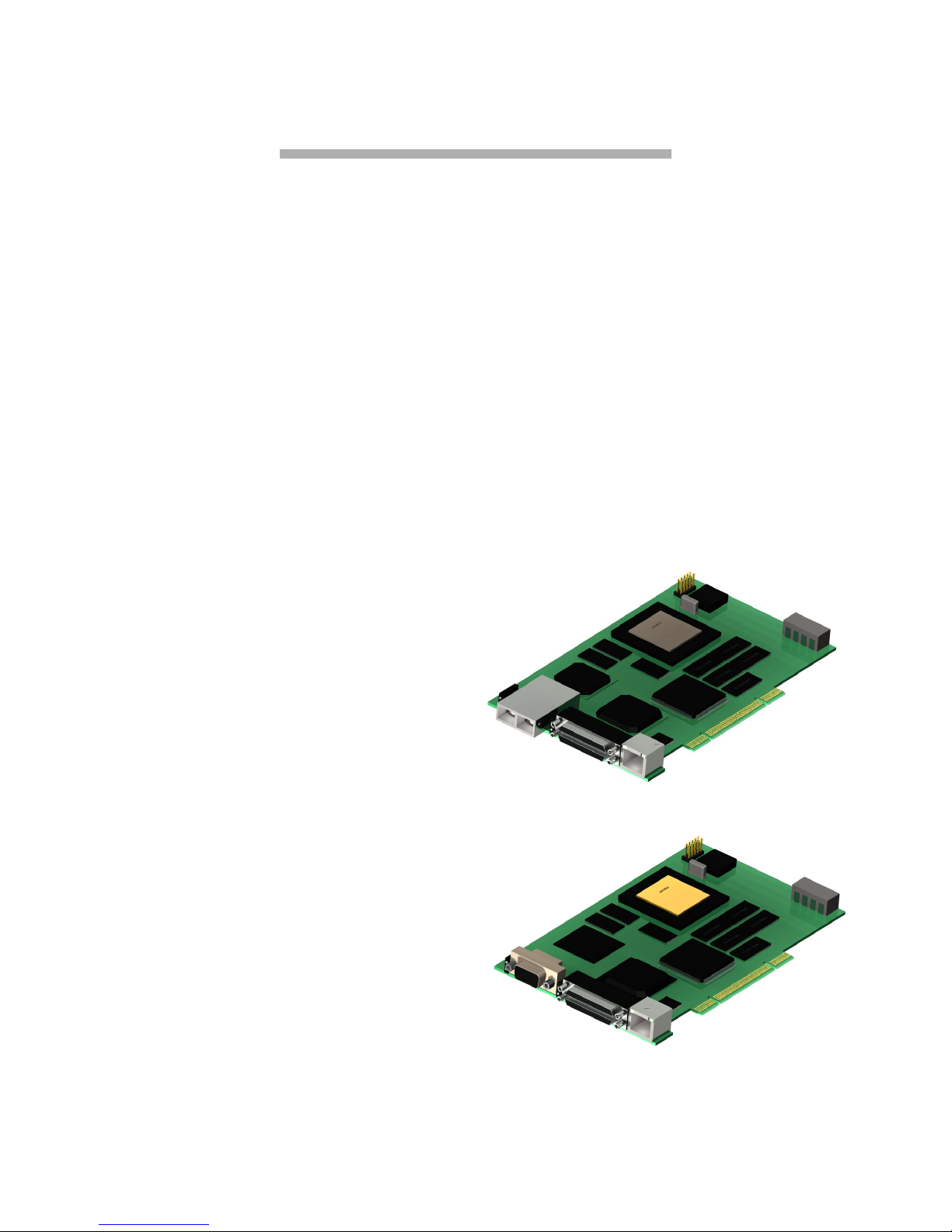
Exhibit 3-1 Graphical representation of the
FibreBridge 1190E with ShortWave fiber optic SE
connector (top) or MIA compliant DB-9 connector
(bottom).
Power
Power (+5 V and +12V) is supplied to the
FibreBridge 1190E through a standard PCI
connector or a 4-pin connector, the default: Amp
Part no: 641737-1. The 1190E is designed to have
5% tolerance to the power supply. A switching
±
regulator generates 3.3V from either 5V or 2V,
requiring 0. 75 A at 1 2V. Jumper-e n abl e d power
from a PCI connector is also possible.
Fibre Channel port
The Fibre Channel port can connect the
FibreBridge to either a Fabric or Arbitrated Loop.
1.0625 gigahertz (100 MB/sec.)
➔
Class 2, Class 3 and Intermix ANSI Fibre
➔
Channel specifications support
PLDA, Public Loop Login (NL_port) and
➔
Fabric Direct Connect (N_port) support
Full Duplex transmission support
➔
MIA compliant DB-9 or Short Wave fiber
➔
optic SE connector
AT TO Technology FibreBridge 1190E Installation and Operation Manual
5
Ethernet port
The 10/100 Base T Ethernet port supports SNMPand Telnet-based monitoring and management
through a command line interface or menu
system.
Serial port
The RS-232 serial port provides support for
remote monitoring and management through a
command line interface or menu system.
Serial/Ethernet RJ45 port
The RJ45 port may be used for either
serial or Ethernet connections depending
on the jumper settings and cable. The
factory sets the jumpers in a serial
configuration across the top and middle
rows of the selector header.
To enable an Ethernet configuration,
Serial/Ethernet
RJ45 port
selector head er
move all the jumpers in the selector
header to the middle and bottom rows.
Attach a standard Ethernet cable.
If using the RJ45 in a serial
PCI
Connector
configuration, create a serial cable
connection with the following pin outs:
(numbered 0). During very high activity,
the LED appears to be steadily lit.
SCSI Activity: shows activity on the SCSI
➔
bus (numbered 0).
Ready: should light after power has been
➔
applied; indicates the board has completed
the initialization process without any
failures and is ready to handle data
transfers.
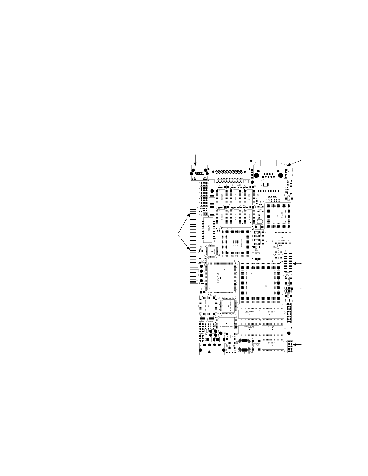
Exhibit 3-2 FibreBridge 1190E board layout.
Ethernet / Serial
Port Connector
Dual stacked
SCSI Connector
SCSl activity
LED
Fibre Channel
Connector
Fibre Channel
activity
and Ready/Faul t
LED
FibreBridge 1190E
Signal Name RJ45 Pin
TX 1
RX 2
Ground 6
LED indicators
FC Activity: LED blinks to show
➔
activity on the Fibre Channel port
4 Pin Power
Connector
JTAG
Header
Reset
Jumper
RS232 Serial
port header
6

4 How to connect SCSI devices to SCSI ports
ATTO FibreBridgeTM SCSI ports are used to connect SCSI storage devices into the Fibre Channel
Storage Area Network (SAN).
A FibreBridge may have the following types of
SCSI ports:
Ultra 2 (LVD) SCSI– 80 MB/sec. max per
➔
bus
Single Ended Ultra SCSI – 40 MB/sec.
➔
max per bus
A FibreBridge with an LVD SCSI personality
module is downward compatible with Single
Ended Ultra SCSI as well as Fast, Wide, or
Narrow SCSI devices.
Each SCSI port is totally independent from the
any other SCSI port. This means that each bus is
capable of supporting 15 devices and each bus is
capable of 40 or 80 MB/sec. (Ultra or Ultra2).
However, you may use externally provided
software striping to create a RAID 0 group that
includes devices from both SCSI busses to
increase overall performance.
Another advantage of independent SCSI ports is
that each SCSI bus auto-negotiates the
appropriate sync rates with the connected devices.
If slower devices are mixed with faster Ultra2
devices, the bus will communicate at the rate of
the slowest device, thus wasting the performance
capabilities of the faster devices. You should
connect slower devices to one SCSI port and
connect faster devices on the other port on your
FibreBridge.
The FibreBridg e su pp or ts a wide var iet y of SC SI
storage devices including stand-alone drives,
removable drives, JBODs, RAIDs, tape, CD and
DVD drives, changers, libraries and magneto
optical drives.
To connect SCSI devices to the ATTO
FibreBridge:
onnect a VHDCI SCSI connector from the
1C
SCSI device to a port on the FibreBridge
1190.
Check the type of cable, cable length limit and
number of devices recommended for each port. It is
important to keep cable lengths as short as possible
to ensure the highest signal quality and
performance.These cable lengths include the wiring
inside the devices.
Device type Number of
devices
Ultra SCSI Single Ended
(SE)
Ultra SCSI Single Ended
(SE)
UltraSCSI High Voltage
Differential (HVD)
Ultra2 SCSI Low Voltage
Differential (LVD)
2 Set the IDs of the SCSI devices connected to
the bridge to a value other than 7. It is
recommended to use a sequential ID
starting at 0 for each device. Each SCSI port
in the ATTO FibreBridge has an internal
factory setting ID of 7, typical for a SCSI
initiator device.
NOTE
The entire SCSI bus will operate at the speed of
the slow est device. If you wish to mi x devices o f di fferent
SCSI speeds on the bridge, it i s best to place them on
separate busses. That is, put the slower devices on
bridge SCSI bus 0, and th e faster d evices on bridge SCSI
bus 1. Each bus is independent so each can operate at
different speeds.
less than 4 3 meters
4 or more 1.5 meters
15 25 meters
15 12 meters
Cable limit
AT TO Technology FibreBridge 1190E Installation and Operation Manual
7
3 Terminate each SCSI bus after the last
device. The bridge is terminated internally.

5 How to connect the Fibre Channel port
The Fibre Channel port(s) on the ATTO FibreBridgeTM connect the bridge into either a Fabric or
Arbitrated Loop.
Fibre Channel technology offers a variety of
cabling options including standard copper,
equalized copper, multimode
fiber optic, and single mode
fiber op ti c.
The FibreBridge 1190E uses
an MIA compliant DB-9 or
Cable length Cable type Cable size Connector
<15 meters unequalized copper DB-9
≥
15 meters
≤
30 meters
Up to 175 meters multi mode fiber optic 62.5 micron SC optic connector
Up to 500 meters multi mode fiber optic 50 micron SC optic connector
equalized copper DB-9
Short Wave fiber optic SE connector.
The type of cable to use varies depending upon
the application, environment and distance. The
following tables illustrate the different cable
options available.
Make sure all cables are anchored securely at both
ends with the proper connectors.
Initial configuration
The FibreBridge can be configured to support
connectivity to arbitrated loop or fabric
topologies. (See Chapter 6 of this manual.)
When connecting these bridges to an F-Port
device, set the Port Connection Mode to “Pointto-Point.”
When connecting to a FL-port device, set
➔
the Port Connector Mode to “Loop” mode.
The FibreBridg e use s pu bl ic lo o p logi n to
➔
log into a FL-Port on a fabric switch.
The FibreBridge Port Connection Mode
➔
can be set using the RS-232, Ethernet, or
in-band com m u n ic at io n li nk s.
8

6 ATTO FibreBridge addressing
The ATTO F ibreBridgeTM allows par allel SC SI dev ices to parti cipate in a F ibr e Chan nel arbitr ated loop
or on a fabric. Fibre Channel and parallel SCSI use different models to address devices. The FibreBridge
translates between these addressing models.
The chart below is a simplified overview of data
and control flow between the application and the
SCSI device through a number of stages.
Application
Operation
System
.
Host Bus
Adapter
PCP
(SCSI)
FibreBridge
SCSI bus
SCSI
device
Read & write da t a
SCSI LUN addressing in OS native form
Maps OS native LUNs
FCP_CMD: LUN plus CDB plus data
Parse Fibre port and Fibr e LUN into SCSI
BUS:Target:LUN
Transport SCSI address, CDB and data
to/from SCSI device
SCSI device operation
Fibre Channel World Wide Name (WWN)
Each Fibre Channel device is assigned a unique
W orld W ide Name (WWN). The WWN is used to
identify all Fibre Channel devices. The 64-bit
WWN has the following format:
Field
Name
Byte 01234 567
Value 2000001086 xxxx
WWN
Format
Company ID Device ID
x
x
The Institute of Electrical and Electronics
Engineers (IEEE) assigns each manufacturer a
unique Company ID. The Device ID field
contains a unique value assigned by ATTO
Technology to every Fibre Channel product
produced by ATTO Technology.
Arbitrated Loop Port Address (AL_PA)
On a Fibre Chann e l Arbi t ra ted Lo op , th e
FibreBridge appears at a single Arbitrated Loop
Port Address (AL_P A ). Each device on an
arbitrated loop is assigned a unique AL_PA
during loop initialization. The FibreBridge
supports both modes of AL_PA assignment,
commonly referred to as
hard
and
soft addr essing
Soft addressing allows the loop initialization
master to assign the FibreBridge a unique AL_P A
during the loop initialization process. The AL_PA
assigned cannot be determined before loop
initialization. For example, adding new devices to
an arbitrated loop may change the AL_PA
assigned to the FibreBridge.
Hard addressing allows a predetermined AL_PA
to be assigned to the FibreBridge. The
FibreBridge will try to acquire the desired hard
AL_PA. If another device has already been
assigned the specified AL_PA, the FibreBridge
will acquire a currently unassigned AL_PA.
ATTO BridgeTools softwa re allows you to select
either hard or soft addressing modes. The default
mode is soft addressing .
Addressing Devices Connected to the
FibreBridge
SCSI devices connected to the FibreBridge also
show up as Fibre Channel LUNs to the host
computer. SCSI devices must be on the same
addressing level as the SCSI portion of the
.
AT TO Technology FibreBridge 1190E Installation and Operation Manual
9

FibreBridge. The FibreBridge SCSI ports must be
set to different SCSI IDs than the devices on the
bus.
Y o u may map SCSI de vices manual ly by using the
Command Line Interface RouteXXX family of
commands. See Chapter 7.1.2 for more details.
ATTO FibreBridge addressing
SCSI devices are mapped manually to desired
Fibre Channel port and Fibre Channel LUNs.
Manual mapping allows you to maximize the
efficiency and performance of your SCSI devices
while allowing great flexibility .
Manual SCSI Device Mapping
The FibreBridge can be commanded to find all the
SCSI devices on its SCSI bus. With this
informat io n yo u th e n de c id e whe r e yo u want to
place these devices on the Fibre Channel ports.
In the chart at right, the SCSI device on SCSI bus
0 at SCSI address of I D 0 LUN 0 is being mapped
to Fibre Port 0 (on the Fibr eBr id g e) at Fibre
Channel LUN 4.
Note: two SCSI devices cannot be mapped to
the same Fibre Port and Fibre Channel LUN.
Also, if the same SCSI device is mapped to two
different Fibre Port and/or Fibre Channel
LUN, these Fibre Port and Fibr e Channel
LUNs will be taken offline automatically until
the conflict is resolved.
Fibre
Port
04000
00010
020130
000150
03010
010011
030085
023087
FC LUN SCSI
BUS
SCSI ID SCSI
LUN
10
 Loading...