

ATTO Technology FC-164E, FC-162E, FC-161E, FC-84EN, FC-82EN Installation And Operation Manual
...Page 1
ATTO Celerity Fibre Channel Host Adapters
Installation and Operation Manual
Celerity FC-164E
16Gb FC quad channel PCIe 3.0 host adapter
Celerity FC-162E
16Gb FC dual channel PCIe 3.0 host adapter
Celerity FC-161E
16Gb FC single channel PCIe 3.0 host adapter
Celerity FC-84EN
8Gb FC quad channel PCIe 2.0 host adapter
Celerity FC-82EN
8Gb FC dual channel PCIe 2.0 host adapter
Celerity FC-81EN
8Gb FC single channel PCIe 2.0 host adapter
4Gb FC quad channel PCIe host adapter
4Gb FC dual channel PCIe host adapter
4Gb FC single channel PCIe host adapter
Celerity FC-44ES
Celerity FC-42ES
Celerity FC-41ES
Page 2

ATTO Technology, Inc.
155 CrossPoint Parkway
Amherst, New York 14068 USA
www.attotech.com
Tel (716) 691-1999
Fax (716) 691-9353
Sales support: sls@attotech.com
Technical support: Monday -- Friday, 8am-6pm EST
techsupp@attotech.com
(716) 691-1999 ext. 242
© 2012 ATTO Technology, Inc. All rights reserved. All brand or product names are trademarks of their respective
holders. No part of this manual may be reproduced in any form or by any means without the express written
permission of ATTO Technology, Inc.
12/2012 PRMA-0344-000
Page 3

Contents
1 ATTO Celerity HBA Features & Overview ........................................................1
Getting started
Celerity FC-164E Adapter
Celerity FC-162E Adapter
Celerity FC-161E Adapter
Celerity FC-84EN Adapter
Celerity FC-82EN Adapter
Celerity FC-81EN Adapter
Celerity FC-44ES Adapter
Celerity FC-42ES Adapter
Celerity FC-41ES Adapter
2 Install Drivers .....................................................................................................13
Windows
OS X
Linux
VMware ESXi 5
VMware ESX/ESXi 4
VMware ESX 3.5
Specialized configurations
3 Hardware Installation .........................................................................................20
Bracket details
Adapter board details
4 Updating Hardware Flash, Drivers ...................................................................29
5 Troubleshooting .................................................................................................31
General suggestions
Mac OS X
Windows
Linux
VMware
Supplemental Guide for VMware ESX/ESXi
Virtual Ports (NPIV)
Appendix A Glossary ............................................................................................i
Appendix B Accessories ......................................................................................iii
Appendix C ATTO Adapter Selection Guides ....................................................iv
Appendix D Standards, Compliances: 16Gb adapters ......................................ix
FCC standards: radio and television interference
Canadian standards
European standards
Page 4

Appendix E Standards, Compliances: 8Gb adapters ........................................x
FCC standards: radio and television interference
Canadian standards
European standards
Appendix F Standards, Compliances: 4Gb adapters ........................................xi
FCC standards: radio and television interference
Canadian standards
European standards
Appendix G Safety, Warranty ..............................................................................xii
Safety
ATTO Technology, Inc. limited warranty
Page 5

1 ATTO Celerity HBA Features & Overview
Note
The ATTO Celerity Fibre Channel family of storage products provides connectivity, intelligence and scalability.
Celerity FC host adapters simplify advanced storage
networking needs such as switching, backup and data
management. Specifically designed to enhance the
functionality of third party fabric hardware and
software, Celerity FC products are the industryleading platform for storage connectivity.
Fibre Channel is a serial communications technology
designed to transfer large amounts of data among a
variety of hardware systems over long distances. It is
a key technology for applications that require shared,
high bandwidth access to storage.
Getting started
In general, to install the ATTO Celerity FC host
adapter, you must:
1 Ensure you have the equipment and software
you need for the installation:
• Celerity FC adapter
• ATTO Celerity CD including drivers, user
manuals and utilities (Installation CD)
• A computer with an available expansion slot
• Storage, cables and connectors
2 Install drivers from the Installation CD for your
operating system. Refer to Install Drivers
page 13.
on
Fibre Channel provides a logical, point-to-point, serial
channel for the transfer of data between a buffer at a
source device and a buffer at a destination device. It
moves buffer contents from one port to another,
without regard to the format or meaning of the data so
different upper level protocols are able to run over
Fibre Channel hardware.
The Fibre Channel architecture is structured as a
hierarchical set of protocol layers. Defined within these
layers are rules for signal interfaces, serial encoding
and decoding, error control, frame format and
communications protocols.
3 Install the configuration software, the ATTO
Configuration Tool, found on the Installation
CD.
4 Install the Celerity adapter. Refer to Hardware
Installation on page 20.
5 Attach storage.
6 If required, configure your Celerity adapter
using the ATTO Configuration Tool.
Default settings are appropriate for most
systems but you may change settings using
the ATTO Configuration Tool.
1
Page 6

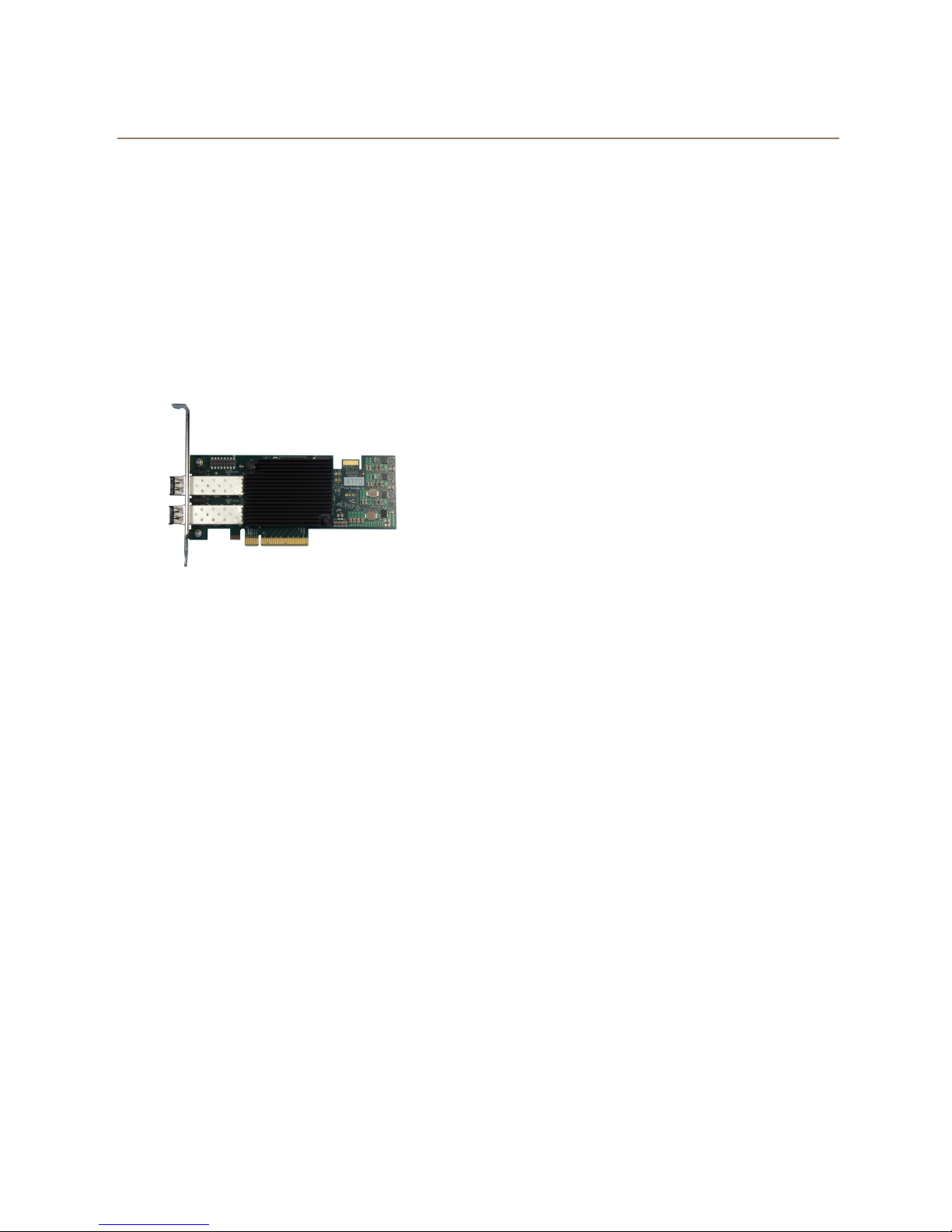
Celerity FC-164E Adapter
The ATTO Celerity FC-164E leverages two nextgeneration storage technologies: PCIe 3.0
interconnect and 16-Gigabit Fibre Channel.
With 16-Gb FC speeds of up to 1600 MB/sec. per
channel, the Celerity FC-164E supports the most
demanding application requirements, including highdefinition video, rich content databases and other
high-bandwidth environments.
ATTO Celerity host adapters are an integrated family
of advanced storage connectivity solutions that are
designed to provide reliable connectivity, intelligence
and scalability.
Technical specifications
• Four independent Fibre Channel ports
• 16-Gigabit data transfer rates
• 3200 MB/sec. maximum full-duplex throughput
per channel
• Supports all FC topologies: fabric, arbitrated
loop and point-to-point
• ANSI Fibre Channel: FC-FS, FC-AL, FCP, FCAL2, FC-PLDA, FC-FLA
• Flash ROM for easy field upgrades
• FC Class 3 support
• Local management and diagnostics
• Buffer credits: 81
• ATTO Advanced Data Streaming (ADS™)
Technology
Advanced FC capabilities
• Supports SNIA HBA API
• Backward compatible with 8-Gb and 4-Gb Fibre
Channel
• Supports target and initiator modes
• Supports FDMI and WMI
• Supports N_Port ID Virtualization (NPIV)
Host bus specifications
• x8 mechanical and x8 electrical PCI Express
interconnect
• Conforms to PCI Express Base Spec 3.0
• Conforms to PCI Express CEM Spec 3.0
• PCI Hot Plug spec 1.0
Environmental & physical specifications
• Length: 6.600 inches
• Height: 2.731 inches
• Operating temperature and Airflow: 0-40 ºC (32104 ºF) - 60lfm minimum recommended;
40-55 ºC (104-132
recommended
• Storage temperature: -40 to 70 ºC (-40 to 158 ºF)
• Relative humidity: 10 to 95% non-condensing
• RoHS compliant
ºF) 100lfm minimum
External connectivity
• Easy to install full height connection bracket
• External LEDs indicate link activity as well as online and speed status for each channel
• Four pluggable 16-Gb optical LC SFP+ modules
included
2 ATTO Technology Inc. Celerity FC Host Adapters Installation and Operation Manual
Software specifications
• Windows XP®, Vista®, 7®, 8®
• Windows Server® 2003, 2008, 2008R2, 2012
• Windows Hyper-V® 2008R2, 2012
• Mac® OS X 10.6.x and later
• RedHat Enterprise Linux®
• SUSE Linux Enterprise® 10.x and 11.x
• openSUSE® 11.3 and 11.4
• CentOS® 5.x and 6.x
• VMware ESXi Server® 5.1
5.x and 6.x
Page 7
Celerity FC-162E Adapter
The ATTO Celerity FC-162E leverages two nextgeneration storage technologies: PCIe 3.0
interconnect and 16-Gigabit Fibre Channel.
With 16-Gb FC speeds of up to 1600 MB/sec. per
channel, the Celerity FC-162E supports the most
demanding application requirements, including highdefinition video, rich content databases and other
high-bandwidth environments.
ATTO Celerity host adapters are an integrated family
of advanced storage connectivity solutions that are
designed to provide reliable connectivity, intelligence
and scalability.
Technical specifications
• Two independent Fibre Channel ports
• 16-Gigabit data transfer rates
• 3200 MB/sec. maximum full-duplex throughput
per channel
• Supports all FC topologies: fabric, arbitrated
loop and point-to-point
• ANSI Fibre Channel: FC-FS, FC-AL, FCP, FCAL2, FC-PLDA, FC-FLA
• Flash ROM for easy field upgrades
• FC Class 3 support
• Local management and diagnostics
• Buffer credits: 81
• ATTO Advanced Data Streaming (ADS™)
Technology
Advanced FC capabilities
• Supports SNIA HBA API
• Backward compatible with 8-Gb and 4-Gb Fibre
Channel
• Supports target and initiator modes
• Supports FDMI and WMI
• Supports N_Port ID Virtualization (NPIV)
Host bus specifications
• x8 mechanical and x8 electrical PCI Express
interconnect
• Conforms to PCI Express Base Spec 3.0
• Conforms to PCI Express CEM Spec 3.0
• PCI Hot Plug spec 1.0
Environmental & physical specifications
• Length: 6.600 inches
• Height: 2.731 inches
• Operating temperature and Airflow: 0-40 ºC (32104 ºF) - 60lfm minimum recommended;
40-55 ºC (104-132
recommended
• Storage temperature: -40 to 70 ºC (-40 to 158 ºF)
• Relative humidity: 10 to 95% non-condensing
• RoHS compliant
ºF) 100lfm minimum
External connectivity
• Easy to install low-profile connection bracket;
included in finished goods packaging
• External LEDs indicate link activity as well as online and speed status for each channel
• Two pluggable 16-Gb optical LC SFP+ modules
included
Software specifications
• Windows XP®, Vista®, 7®, 8®
• Windows Server® 2003, 2008, 2008R2, 2012
• Windows Hyper-V® 2008R2, 2012
• Mac® OS X 10.6.x and later
• RedHat Enterprise Linux®
• SUSE Linux Enterprise® 10.x and 11.x
• openSUSE® 11.3 and 11.4
• CentOS® 5.x and 6.x
• Fedora Linux® 14.x - 15.x
• VMware ESXi Server® 5.1
5.x and 6.x
3
Page 8

Celerity FC-161E Adapter
The ATTO Celerity FC-161E leverages two nextgeneration storage technologies: PCIe 3.0
interconnect and 16-Gigabit Fibre Channel.
With 16-Gb FC speeds of up to 1600 MB/sec. per
channel, the Celerity FC-161E supports the most
demanding application requirements, including highdefinition video, rich content databases and other
high-bandwidth environments.
ATTO Celerity host adapters are an integrated family
of advanced storage connectivity solutions that are
designed to provide reliable connectivity, intelligence
and scalability.
Technical specifications
• One independent Fibre Channel port
• 16-Gigabit data transfer rates
• 3200 MB/sec. maximum full-duplex throughput
per channel
• Supports all FC topologies: fabric, arbitrated
loop and point-to-point
• ANSI Fibre Channel: FC-FS, FC-AL, FCP, FCAL2, FC-PLDA, FC-FLA
• Flash ROM for easy field upgrades
• FC Class 3 support
• Local management and diagnostics
• Buffer credits: 81
• ATTO Advanced Data Streaming (ADS™)
Technology
Advanced FC capabilities
• Supports SNIA HBA API
• Backward compatible with 8-Gb and 4-Gb Fibre
Channel
• Supports target and initiator modes
• Supports FDMI and WMI
• Supports N_Port ID Virtualization (NPIV)
Host bus specifications
• x8 mechanical and x8 electrical PCI Express
interconnect
• Conforms to PCI Express Base Spec 3.0
• Conforms to PCI Express CEM Spec 3.0
• PCI Hot Plug spec 1.0
Environmental & physical specifications
• Length: 6.600 inches
• Height: 2.731 inches
• Operating temperature and Airflow: 0-40 ºC (32104 ºF) - 60lfm minimum recommended;
40-55 ºC (104-132 ºF) 100lfm minimum
recommended
• Storage temperature: -40 to 70 ºC (-40 to 158 ºF)
• Relative humidity: 5 to 95% non-condensing
• 10.97W
• RoHS compliant
External connectivity
• Easy to install low-profile connection bracket;
included in finished goods packaging
• External LEDs indicate link activity as well as online and speed status for each channel
• One pluggable 16-Gb optical LC SFP+ modules
included
4 ATTO Technology Inc. Celerity FC Host Adapters Installation and Operation Manual
Software specifications
• Windows XP®, Vista®, 7®, 8®
• Windows Server® 2003, 2008, 2008R2, 2012
• Windows Hyper-V® 2008R2, 2012
• Mac® OS X 10.6.x and later
• RedHat Enterprise Linux®
• SUSE Linux Enterprise® 10.x and 11.x
• openSUSE® 11.3 and 11.4
• CentOS® 5.x and 6.x
• Fedora Linux® 14.x - 15.x
• VMware ESXi Server® 5.1
5.x and 6.x
Page 9
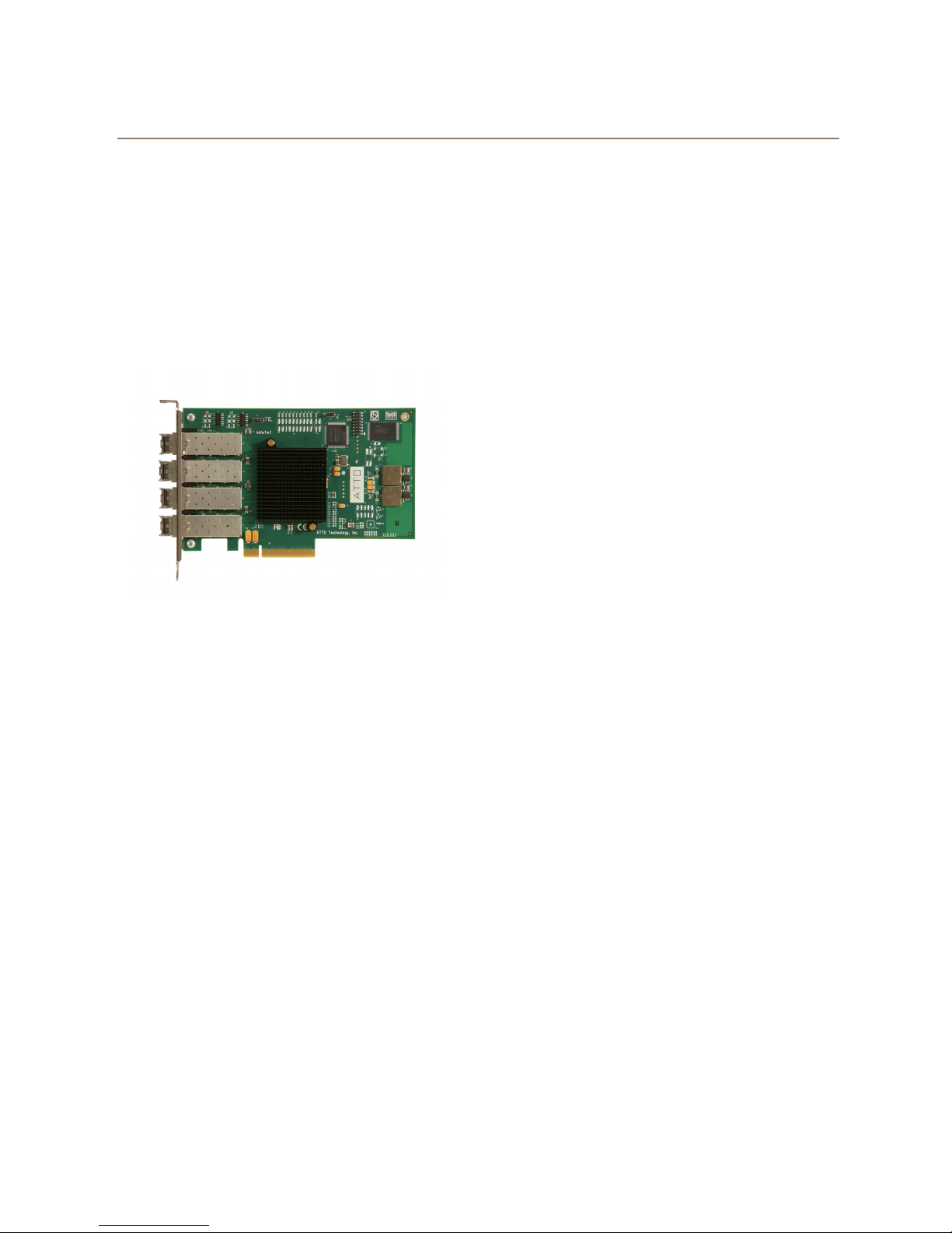
Celerity FC-84EN Adapter
The ATTO Celerity FC-84EN leverages two nextgeneration storage technologies: PCIe 2.0
interconnect and 8-Gigabit Fibre Channel.
With 8-Gb FC speeds of up to 1600 MB/sec. per
channel, the Celerity FC-84EN supports the most
demanding application requirements, including highdefinition video, rich content databases and other
high-bandwidth environments.
ATTO Celerity host adapters are an integrated family
of advanced storage connectivity solutions that are
designed to provide reliable connectivity, intelligence
and scalability.
Technical specifications
• Four independent Fibre Channel ports
• 8-Gigabit data transfer rates
• 1600 MB/sec. maximum full-duplex throughput
per channel
• Supports all FC topologies: fabric, arbitrated
loop and point-to-point
• ANSI Fibre Channel: FC-FS, FC-AL, FCP, FCAL2, FC-PLDA, FC-FLA
• Flash ROM for easy field upgrades
• FC Class 3 support
• Local management and diagnostics
• Buffer credits: 41
• ATTO Advanced Data Streaming (ADS™)
Technology
Advanced FC capabilities
• Supports SNIA HBA API
• Backward compatible with 4-Gb and 2-Gb Fibre
Channel
• Supports target and initiator modes
• Supports Windows®
• Supports N_Port ID Virtualization (NPIV)
FDMI and WMI
Host bus specifications
• x8 mechanical and x8 electrical PCI Express
interconnect
• Conforms to PCI Express Base Spec 2.0
• Conforms to PCI Express CEM Spec 2.0
• PCI Hot Plug spec 1.0
Environmental & physical specifications
• Length: 6.6 inches
• Height: 3.987 inches
• Operating temperature: 0-40 ºC (32-104 ºF)
• Storage temperature: -40 to 70 ºC (-40 to 158 ºF)
• Relative humidity: 10 to 90% non-condensing
• 7.8 W (typical)
• 100 lf/m (minimum) airflow recommended
• RoHS compliant
External connectivity
• Easy to install full height connection bracket
• External LEDs for on-line and speed status for
each channel
• Four pluggable 8-Gb optical LC SFP+ modules
included
Software specifications
• Windows XP®, Vista®, 7®, 8®
• Windows Server® 2003, 2008, 2012
• Mac® OS X 10.5.x and up
• RedHat Enterprise Linux®
• RedHat Enterprise Linux®
• RedHat Enterprise Linux®
• SUSE Linux Enterprise® 9.x (2.6.x kernels)
• SUSE Linux Enterprise® 10.x (2.6.x kernels)
• Fedora Core Linux® 7.x (2.6.x kernels)
• Fedora Core Linux® 8.x (2.6.x kernels)
• VMware ESX Server® 3.5 - 4.x
• VMware ESXi Server® 4.x - 5.x
4.x (2.6.x kernesl)
5.x (2.6.x kernels)
6.x (2.6.x kernels)
5
Page 10
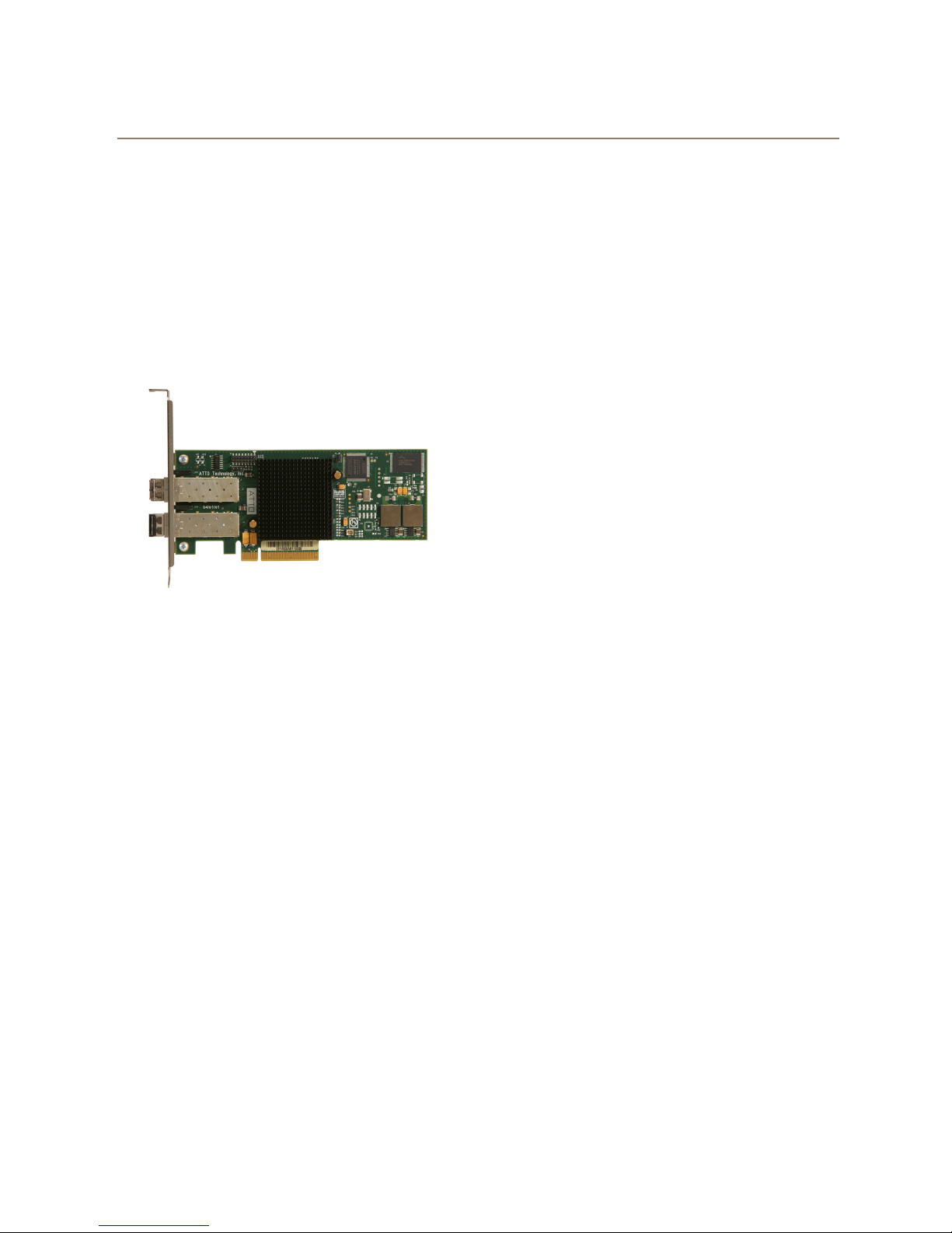
Celerity FC-82EN Adapter
The ATTO Celerity FC-82EN leverages two nextgeneration storage technologies: PCIe 2.0
interconnect and 8-Gigabit Fibre Channel.
With 8-Gb FC speeds of up to 1600 MB/sec. per
channel, the Celerity FC-82EN supports the most
demanding application requirements, including highdefinition video, rich content databases and other
high-bandwidth environments.
ATTO Celerity host adapters are an integrated family
of advanced storage connectivity solutions that are
designed to provide reliable connectivity, intelligence
and scalability.
Technical specifications
• Two independent Fibre Channel ports
• 1600 MB/sec. maximum throughput per channel
in full-duplex mode
• 8-Gigabit data transfer rates
• Conforms to PCI Express Low Profile formfactor specifications
• Supports all FC topologies: fabric, arbitrated
loop and point-to-point
• ANSI Fibre Channel: FC-FS, FC-AL, FCP, FCAL2, FC-PLDA, FC-FLA
• Flash ROM for easy field upgrades
• FC Class 3 support
• Local management and diagnostics
• Buffer credits: 41
• ATTO Advanced Data Streaming (ADS™)
Technology
Advanced FC capabilities
• Supports SNIA HBA API
• Backward compatible with 4-Gb and 2-Gb Fibre
Channel
• Supports target and initiator modes
• Supports Windows®
• Supports N_Port ID Virtualization (NPIV)
FDMI and WMI
Host bus specifications
• x8 mechanical and x8 electrical PCI Express
interconnect
• Conforms to PCI Express Base Spec 2.0
Conforms to PCI Express CEM Spec 2.0
• PCI Hot Plug spec 1.0
Environmental & physical specifications
• Length: 6.6 inches
• Height: 2.731 inches
• Operating temperature: 0-40 ºC (32-104 ºF)
• Storage temperature: -40 to 70 ºC (-40 to 158 ºF)
• Relative humidity: 10 to 90% non-condensing
• 5.9W (typical)
• 100 lf/m (minimum) airflow recommended
• RoHS compliant
External connectivity
• Easy to install low-profile connection bracket;
included in finished goods packaging
• External LEDs for on-line and speed status for
each channel
• Two pluggable 8-Gb optical LC SFP+ modules
included
Software specifications
• Windows XP®, Vista®, 7®, 8®
• Windows Server® 2003, 2008, 2012
• Mac® OS X 10.5.x and up
• RedHat Enterprise Linux®
• RedHat Enterprise Linux®
• RedHat Enterprise Linux®
• SUSE Linux Enterprise® 9.x (2.6.x kernels)
• SUSE Linux Enterprise® 10.x (2.6.x kernels)
• Fedora Core Linux® 7.x (2.6.x kernels)
• Fedora Core Linux® 8.x (2.6.x kernels)
• VMware ESX Server® 3.5 - 4.x
• VMware ESXi Server® 4.x - 5.x
4.x (2.6.x kernels)
5.x (2.6.x kernels)
6.x (2.6.x kernels)
6 ATTO Technology Inc. Celerity FC Host Adapters Installation and Operation Manual
Page 11
Celerity FC-81EN Adapter
The ATTO Celerity FC-81EN leverages two nextgeneration storage technologies: PCIe 2.0
interconnect and 8-Gigabit Fibre Channel.
With 8-Gb FC speeds of up to 1600 MB/sec. per
channel, the Celerity FC-81EN supports the most
demanding application requirements, including highdefinition video, rich content databases and other
high-bandwidth environments.
ATTO Celerity host adapters are an integrated family
of advanced storage connectivity solutions that are
designed to provide reliable connectivity, intelligence
and scalability.
Technical specifications
• One independent Fibre Channel port
• 8-Gigabit FC data transfer rates
• 1600 MB/sec. throughput in full-duplex mode
• Supports all FC topologies: fabric, arbitrated
loop and point-to-point
• ANSI Fibre Channel: FC-FS, FC-AL, FCP, FCAL2, FC-PLDA, FC-FLA
• Flash ROM for easy field upgrades
• FC Class 3 support
• Local management and diagnostics
• Buffer credits: 41
• ATTO Advanced Data Streaming (ADS™)
Technology
Advanced FC capabilities
• Supports SNIA HBA API
• Backward compatible with 4-Gb and 2-Gb Fibre
Channel
• Supports target and initiator modes
• Supports Windows
• Supports N_Port ID Virtualization (NPIV)
FDMI and WMI
Host bus specifications
• x8 mechanical and x8 electrical PCI Express
interconnect
• Conforms to PCI Express Base Spec 2.0
• Conforms to PCI Express CEM Spec 2.0
• PCI Hot Plug spec 1.0
Environmental & physical specifications
• Length: 6.6 inches
• Height: 2.731 inches
• Operating temperature: 0-45ºC (32-113ºF)
• Storage temperature: -40 to 70ºC (-40 to 158ºF)
• Relative humidity: 10 to 90% non-condensing
• 5.3 W (typical)
• 100 lf/m (minimum) airflow recommended
• RoHS compliant
External connectivity
• Easy to install low-profile connection bracket;
included in finished goods packaging
• External LEDs for on-line and speed status for
each channel
• One pluggable 8-Gb optical LC SFP+ module
included
Software specifications
• Windows XP®, Vista®, 7®, 8®
• Windows Server® 2003, 2008, 2012
• Mac® OS X 10.5.x and up
• RedHat Enterprise Linux®
• RedHat Enterprise Linux®
• RedHat Enterprise Linux®
• SUSE Linux Enterprise® 9.x (2.6.x kernels)
• SUSE Linux Enterprise® 10.x (2.6.x kernels)
• Fedora Core® Linux 7.x (2.6.x kernels)
• Fedora Core® Linux 8.x (2.6.x kernels)
• VMware ESX Server® 3.5 - 4.x
• VMware ESXi Server® 4.x - 5.x
4.x (2.6.x kernels)
5.x (2.6.x kernels)
6.x (2.6.x kernels)
7
Page 12

Celerity FC-44ES Adapter
The Celerity FC-44ES uses PCI Express Interconnect
and 4-Gigabit Fibre Channel to provide 4-Gb FC
speeds of up to 800 MB/sec. per channel. The FC44ES supports high-definition video, rich content
databases and other high bandwidth environments.
The FC-44ES uses PCI Express, a serial, high-speed
connection that supports aggregate throughput up to 4
GB/sec. (x8 PCIe) full-duplex. Software compatible
with existing PCI and PCI-X products, the FC-44ES
uses the same device drivers as other Celerity FC
family products, simplifying installation and support.
Technical specifications
• 4 independent Fibre Channel ports
• 4-Gigabit data transfer rates per channel
• 800 MB/sec. maximum full-duplex throughput
per channel
• Supports all FC topologies: fabric, arbitrated
loop and point-to-point
• ANSI Fibre Channel: FC-FS, FC-AL, FCP, FCAL2, FC-PLDA, FC-FLA
• Flash ROM for easy field upgrades
• FC Class 3 support
• Local management and diagnostics
• Buffer credits: 8 @ 512 Bytes; 8 @ 2 Kilobytes
• ATTO Advanced Data Streaming (ADS™)
Technology
Advanced FC Capabilities
• Supports SNIA HBA API
• On-demand automatic negotiation among 4-Gb,
2-Gb and 1-Gb Fibre Channel
• Supports target and initiator modes
• Supports Windows
FDMI and WMI
Host bus specifications
• x8 mechanical and x8 electrical PCI Express
Interconnect
• Conforms to PCI Express Base Spec 1.0a
• Conforms to PCI Express CEM Spec 1.0a
• PCI Express to PCI/PCI-X Bridge spec 1.0
Environmental & physical specifications
• Conforms to PCI standard height, half length
form-factor specifications
• Length: 6.525 inches
• Height: 3.81 inches
• Operating temperature: 0-45ºC (32-113ºF)
• Storage temperature: -40 to 70ºC (-40 to 158ºF)
• Relative humidity: 10 to 90% non-condensing
• 12V@ 2.1A (max.)
• 3.3V @ 3.0A (max.)
• 100 lf/m (minimum) airflow recommended
• RoHS compliant
External connectivity
• Easy-to-install full height connection plate
• External LEDs for on-line and speed status for
each channel
• 4 pluggable optical LC SFP transceivers
included
Software specifications
• Windows XP®, Vista®, 7®, 8®
• Windows Server® 2003, 2008, 2012
• Mac® OS X 10.5.x and up
• RedHat Enterprise Linux®
• RedHat Enterprise Linux®
• RedHat Enterprise Linux®
• RedHat Enterprise Linux®
• RedHat Enterprise Linux®
• SUSE Linux Enterprise® 8.x (2.4.x kernels)
• SUSE Linux Enterprise® 9.x (2.6.x kernels)
• SUSE Linux Enterprise® 10.x (2.6.x kernels)
• Fedora Core Linux® 7.x (2.6.x kernels)
• Fedora Core Linux® 8.x (2.6.x kernels)
• Fedora Linux® 9.x (2.6.x kernels)
• Solaris® 9.x x86
• Solaris® 10.x x86
• VMware ESX Server® 3.5
2.x (2.4.x kernels)
3.x (2.4.x kernels)
4.x (2.6.x kernels)
5.x (2.6.x kernels)
6.x (2.6.x kernels)
8 ATTO Technology Inc. Celerity FC Host Adapters Installation and Operation Manual
Page 13
Celerity FC-42ES Adapter
The Celerity FC-42ES is a dual-channel host adapter
providing port density for Enterprise server and
workstation applications. With 4-Gb FC speeds of up
to 800 MB/sec. per channel, the FC-42ES supports
the most demanding application requirements.
Additionally the FC-42ES uses the latest in host
interconnect technology, PCI Express, a serial, highspeed connection that supports aggregate throughput
up to 4 GB/sec. (x8 PCIe) full-duplex.
The FC-42ES is software compatible with existing PCI
and PCI-X products using the same device drivers as
other Celerity FC family products, simplifying user
installation and support. It is backward compatible with
existing 2-Gb and 1-Gb Fibre Channel infrastructure.
Technical specifications
• 2 independent Fibre Channel ports
• 4-Gigabit data transfer rates per channel
• 800 MB/sec. maximum full-duplex throughput
per channel
• Supports all FC topologies: direct fabric,
arbitrated loop and point-to-point
• ANSI Fibre Channel: FC-FS, FC-AL, FCP, FCAL2, FC-PLDA, FC-FLA
• Flash ROM for easy field upgrades
• FC Class 3 support
• Local management and diagnostics
• Buffer credits: 8 @ 512 Bytes; 8 @ 2 Kilobytes
• ATTO Advanced Data Streaming (ADS™)
Technology
Advanced FC Capabilities
• Supports SNIA HBA API
• On-demand automatic negotiation among 4-Gb,
2-Gb and 1-Gb Fibre Channel
• Supports target and initiator modes
• Supports Windows
FDMI and WMI
Host bus specifications
• x4 mechanical and x4 electrical PCI Express
Interconnect (RoHS compliant)
• Conforms to PCI Express Base Spec 1.0a
• Conforms to PCI Express CEM Spec 1.0a
• PCI Express to PCI/PCI-X Bridge spec 1.0
Environmental & physical specifications
• Operating temperature: 0-45ºC (32-113ºF)
• Storage temperature: -40 to 70ºC (-40 to 158ºF)
• Relative humidity: 10 to 90% non-condensing
• 100 lf/m (minimum) airflow recommended
• Conforms to PCI half height, half length formfactor specifications
• 12V@ 4A (max.); 3.3V @ 1.5A (max.)
• Length: 5.6 inches
• Height: 2.712 inches
• RoHS compliant
External connectivity
• Easy to install low-profile connection bracket;
included in finished goods packaging
• External LEDs for on-line and speed status for
each channel
• 2 pluggable optical LC SFP transceivers
included
Software specifications
• Windows XP®, Vista®, 7®, 8®
• Windows Server® 2003, 2008, 2012
• Mac® OS X 10.5.x and up
• RedHat Enterprise Linux®
• RedHat Enterprise Linux®
• RedHat Enterprise Linux®
• RedHat Enterprise Linux®
• RedHat Enterprise Linux®
• SUSE Linux Enterprise® 8.x (2.4.x kernels)
• SUSE Linux Enterprise® 9.x (2.6.x kernels)
• SUSE Linux Enterprise® 10.x (2.6.x kernels)
• Fedora Core Linux® 7.x (2.6.x kernels)
• Fedora Core Linux® 8.x (2.6.x kernels)
• Fedora Linux® 9.x (2.6.x kernels)
• Solaris® 9.x x86
• Solaris® 10.x x86
• VMware ESX Server® 3.5
2.x (2.4.x kernels)
3.x (2.4.x kernels)
4.x (2.6.x kernels)
5.x (2.6.x kernels)
6.x (2.6.x kernels)
9
Page 14

Celerity FC-41ES Adapter
The Celerity FC-41ES is a single-channel host adapter
providing support for the most demanding application
requirements. With 4-Gb FC speeds of up to 800
MB/sec. per channel, the FC-41ES is a cost effective
connectivity solution for environments requiring
maximum throughput.
The FC-41ES uses the latest in host interconnect
technology: PCI Express, a serial, high-speed
connection that supports aggregate throughput up to 2
GB/sec. (x4 PCIe) full-duplex. The FC-41ES is
software compatible with existing PCI and PCI-X
products using the same device drivers as other
Celerity FC products, simplifying user installation and
support. It is backward compatible with existing 2-Gb
and 1-Gb Fibre Channel infrastructure, protecting
existing technology investments.
Host bus specifications
• x4 mechanical and x4 electrical PCI Express
Interconnect (RoHS compliant)
• Conforms to PCI Express Base Spec 1.0a
• Conforms to PCI Express CEM Spec 1.0a
• PCI Express to PCI/PCI-X Bridge spec 1.0
Environmental & physical specifications
• Conforms to PCIe low profile form factor
specifications
• Length: 5.600 inches
• Height: 2.712 inches
• Operating temperature: 0-45ºC (32-113ºF)
• Storage temperature: -40 to 70ºC (-40 to 158ºF)
• Relative humidity: 10 to 90% non-condensing
• 12V@ 0.4A (max.)
• 3.3V @ 1.0A (max.)
• 100 lf/m (minimum) airflow recommended
• RoHS compliant
External connectivity
• Easy-to-install full height connection plate
• External LEDs for on-line and speed status
• Pluggable optical LC SFP transceivers included
Technical specifications
• 1 Fibre Channel port
• 4-Gigabit FC data transfer rates
• 800 MB/sec. maximum full-duplex throughput
• Supports all FC topologies: fabric, arbitrated
loop and point-to-point
• ANSI Fibre Channel: FC-FS, FC-AL, FCP, FCAL2, FC-PLDA, FC-FLA
• Flash ROM for easy field upgrades
• FC Class 3 support
• Local management and diagnostics
• Buffer credits: 8 @ 512 Bytes; 8 @ 2 Kilobytes
• ATTO Advanced Data Streaming (ADS™)
Technology
Advanced FC Capabilities
• Supports SNIA HBA API
• On-demand automatic negotiation among 4-Gb,
2-Gb and 1-Gb Fibre Channel
• Supports target and initiator modes
• Supports Windows
FDMI and WMI
Software specifications
• Windows XP®, Vista®, 7®, 8®
• Windows Server® 2003, 2008, 2012
• Mac® OS X 10.5.x and up
• RedHat Enterprise Linux®
• RedHat Enterprise Linux®
• RedHat Enterprise Linux®
• RedHat Enterprise Linux®
• RedHat Enterprise Linux®
• SUSE Linux Enterprise® 8.x (2.4.x kernels)
• SUSE Linux Enterprise® 9.x (2.6.x kernels)
• SUSE Linux Enterprise® 10.x (2.6.x kernels)
• Fedora Core Linux® 7.x (2.6.x kernels)
• Fedora Core Linux® 8.x (2.6.x kernels)
• Fedora Linux® 9.x (2.6.x kernels)
• Solaris® 9.x x86
• Solaris® 10.x x86
• VMware ESX Server® 3.5
2.x (2.4.x kernels)
3.x (2.4.x kernels)
4.x (2.6.x kernels)
5.x (2.6.x kernels)
6.x (2.6.x kernels)
10 ATTO Technology Inc. Celerity FC Host Adapters Installation and Operation Manual
Page 15

Selection guide: Celerity 16-Gb adapters
Product Features FC-164E FC-162E FC-161E
Fibre Channel Ports 421
FC protocol 16-Gb 16-Gb 16-Gb
Maximum Transfer Rate (full duplex) 6400 MB/sec 3200 MB/sec 1600 MB/sec.
Bus type PCIe 3.0 PCIe 3.0 PCIe 3.0
Bus characteristics 8 lane 8 lane 8 lane
Optical interface SFP+ LC SFP+ LC SFP+ LC
Maximum cable length
Low profile form factor
Advanced Data Streaming (ADS™) Technology
Software RAID support
Developer's kit (Target Mode & API)
Windows support
Linux driver support
Macintosh OS X driver support
VMware ESXi Server 5.x
1 ATTO Express Power Center recommended
1
50m@8-Gb
35m@16-Gb
50m@8-Gb
35m@16-Gb
50m@8-Gb
35m@16-Gb
Selection guide: Celerity 8-Gb adapters
Product Features FC-84EN FC-82EN FC-81EN
Fibre Channel Ports 421
FC protocol 8-Gb 8-Gb 8-Gb
Maximum Transfer Rate (half duplex) 3.2 GB/sec 1.6 GB/sec 800 MB/sec.
Maximum Transfer Rate (full duplex) 6.4 GB/sec 3.2 GB/sec 1.6 GB/sec.
Bus type PCIe 2.0 PCIe 2.0 PCIe 2.0
Bus characteristics 8 lane 8 lane 4 lane
Optical interface SFP+ LC SFP+ LC SFP+ LC
300m@2-Gb
150m@4-Gb
50m@8-Gb
Maximum cable length
Low profile form factor
Advanced Data Streaming (ADS™) Technology
Software RAID support
Developer's kit (Target Mode & API)
Windows support
Linux driver support
Macintosh OS X driver support
VMware ESXi Server 5.x
VMware ESX/ESXi Server 4.x
VMware ESX Server 3.5
1 ATTO Express Power Center recommended
1
300m@2-Gb
150m@4-Gb
50m@8-Gb
300m@2-Gb
150m@4-Gb
50m@8-Gb
11
Page 16

Selection guide: Celerity 4-Gb adapters
Product Features FC-44ES FC-42ES FC-41ES
Fibre Channel Ports 421
FC protocol 4-Gb 4-Gb 4-Gb
Maximum Transfer Rate (half duplex) 1.6 GB/sec 800 MB/sec 400 MB/sec.
Maximum Transfer Rate (full duplex) 2 GB/sec 1 GB/sec 800 MB/sec.
Bus type PCIe PCIe PCIe
Bus characteristics 8 lane 4 lane 4 lane
Optical interface SFP LC SFP LC SFP LC
Maximum cable length
Low profile form factor
Advanced Data Streaming (ADS™) Technology
Software RAID support
Developer's kit (Target Mode & API)
Windows support
Linux driver support
Macintosh OS X driver support
VMware ESX Server 3.5
Novell Netware
Solaris
Free BSD
1 ATTO Express Power Center recommended
300m@2-Gb
150m@4-Gb
300m@2-Gb
150m@4-Gb
300m@2-Gb
150m@4-Gb
12 ATTO Technology Inc. Celerity FC Host Adapters Installation and Operation Manual
Page 17

2 Install Drivers
Note
Note
Note
Before installing your Celerity adapter, you must configure your system to recognize and use it by installing drivers
for your operating system.
Configure your system to recognize and use your
Celerity adapter by installing drivers for your operating
system.
If you already have one or more Celerity
adapters installed and you are installing
additional adapter(s), you do not need to
perform any of these procedures unless you
are updating a previously installed driver.
Windows
Windows Vista and later may utilize a new
User Account Control Feature. Because of
this there may be additional confirmations
that will need to be performed to properly
install the driver. These confirmations
normally consist of a dialog where the user
has to give Windows permission to perform
an action. If you do not have the correct
privileges during this, you will be prompted
for an actual user name and password. You
may need to contact your system
administrator if you do not have this
information.
ATTO Celerity adapters ship with the latest firmware
installed. The Celerity FC Installation CD shipped with
your adapter also contains the latest driver.
The Installation CD automatically starts when inserted
in the system CD-ROM drive. Navigate the easy-touse HTML-based menu to find the driver for your
adapter and operating system.
The Celerity FC Installation CD referred to in these
instructions can be the Installation CD shipped with
your adapter, a folder containing the latest
downloaded and expanded driver, a Celerity FC
installation floppy disk, or a USB flash drive.
2 Insert the Installation CD. The ATTO
Installation CD guide should appear. If not,
navigate to the root of the CD and run the
AUTORUN.BAT batch file.
3 Click on Windows Drivers.
4 Click on Windows XX Driver link based on the
HBA speed (4Gb, 8Gb or 16Gb) and operating
system (x86, x64 or Itanium) in use. If you are
unsure which version you are using, please
contact your system administrator.
5 Click Install Windows Driver XX next to the
appropriate item to initiate the driver setup
program.
6 Follow the on-screen instructions to complete
the driver installation.
Driver Installation
1 Power on your system and log in as the
administrator or a user with proper
administrative privileges.
WHQL Certified Drivers are available for
select Celerity Fibre Channel HBAs. If
available, these drivers will be listed below
the default Windows drivers.
13
Page 18

Creating Windows installation media
Note
Note
Note
Note
Note
Note
Installation media is required when
performing an installation of Windows to a
hard drive that is controlled by a Celerity FC
host adapter. A floppy is required for
Windows 2000, XP or 2003. Windows 8, 7,
Vista, Server 2012 and 2008 can utilize other
media such as removable USB stick. This
procedure does not apply to Itanium systems
as the Celerity FC driver does not support
boot functionality on these systems.
1 Power on your system and log in as the
administrator or a user with proper
administrative privileges
OS X
Some ATTO Celerity FC drivers are included
on the Mac OS X Mountain Lion (10.8) CD
and do not require additional installation
steps, however we recommend you visit the
ATTO website to check for, and download,
the latest drivers and firmware.
2 Insert the Installation CD. The ATTO
Installation CD guide should appear. If not,
navigate to the root of the CD and run the
AUTORUN.BAT batch file
3 Click on Windows Drivers.
4 Click on Windows XX Driver link based on the
HBA speed (4Gb, 8Gb or 16Gb) and operating
system (x86, x64 or Itanium) in use. If you are
unsure which version you are using, please
contact your system administrator.
5 Click Install Windows Driver XX next to the
appropriate item to initiate the driver setup
program.
6 Follow the on-screen instructions to complete
the driver installation.
Installing a fresh copy of OS X onto a disk
attached to a Celerity FC adapter (only for
8Gb FC adapters)
Boot support is available on Intel-based
systems only.
The ATTO Celerity FC host adapters support
OS X Mountain Lion, Lion, Snow Leopard,
Leopard and Tiger operating systems. ATTO
16Gb and 8Gb FC adapters also have EFI
boot support on Intel based systems.
Driver Installation (for all ATTO FC host
adapters)
1 Power on your system and log in as the
administrator or a user with proper
administrative privileges.
2 Insert the Installation CD.
3 After the CD mounts, open the Celerity volume
on the desktop.
4 Open the Drivers folder.
5 Open the folder corresponding to the speed of
the HBA.
6 Open the folder corresponding to the OS X
version in use.
7 Launch the installer package.
8 Follow the on-screen instructions.
The EFI boot driver is disabled by default. To
enable it, use the ATTO Configuration Tool in
an existing OS X installation, or use the EFI
Configuration utility built into the EFI driver
(see the procedure below for launching the
utility).
This is a two step process. First step is to
adjust adapter settings with the EFI
Configuration utility. Second step is to install
the OS X onto a disk attached to the adapter.
Please review thoroughly to ensure you are
using the second step corresponding to the
OS X version available in your system.
14 ATTO Technology Inc. Celerity FC Host Adapters Installation and Operation Manual
Page 19

Adjusting adapter settings with the EFI
Note
Note
Configuration Utility (only for 16Gb and
8Gb FC adapters)
Depending on your configuration, it may be
necessary to adjust adapter NVRAM
settings prior to performing the OS X
installation. For example, you may need to
modify the connection mode or data rate.
The EFI configuration utility can be launched
from the EFI shell.
An EFI shell is not included with Intel Macs.
ATTO recommends rEFIt, which is available
for free from
Once you have downloaded the DMG or
rEFIt, follow these steps to open the EFI
Configuration Utility.
1 Burn the rEFIt DMG file to a CD. Do not remove
the CD.
2 Shut down the system and install the Celerity
adapter
3 With the rEFIt CD inserted, boot the system
while pressing and holding ‘C’ key. This will
boot the rEFIt CD.
4 The rEFIt boot menu will appear which contains
a series of icons. Release the ‘C’ key and use
the arrows to highlight the “Start EFI Shell” icon.
Press ‘Return’ to enter the EFI Shell.
5 At the prompt, enter the ‘driver-b’ command.
Scroll through the list of installed EFI drivers
and find the ATTO Celerity driver. There may
be more than one entry based on the number
and type of adapter(s). Note the two or three
digit hexadecimal driver handle on the far left of
the screen.
6 At the prompt, enter ‘drvcfg -s {handle}’ where
{handle} is the hexadecimal number from the
previous step. This will launch the EFI
Configuration Utility for the associated adapter.
http://refit.sourceforge.net
.
7 Use the on-screen menus to configure your
adapter. Help is available at the bottom of the
screen.
8 When exiting the configuration utility, if you
changed any settings, the system will restart
the adapter so the new settings take effect.
9 At the prompt, enter ‘exit’ to return to the rEFIt
boot menu or ‘reset’ to restart the system.
Installing OS X Mountain Lion, Lion or
Snow Leopard onto a disk attached to a
Celerity adapter (only for 16Gb and 8Gb
FC adapters)
1 Install your Celerity adapter and connect your
storage.
2 If you are launching the OS X installation by
booting the installation DVD:
a. Launch the installation and proceed to the
“Select the disk where you want to install
Mac OS X” screen
b. If you need to partition your disk, open Disk
Utility from the Utilities menu. Once you
partition your disk and exit, the newly
created volume will appear in the installer
window.
3 If you are launching the OS X installation from
an existing OS X installation:
a. If you need to partition disk, open Disk
Utility from /Applications/Utilities. Partition
your disk and exit.
b. Launch the installation DVD and proceed
to the “Select the disk where you want to
install Mac OS X” screen.
4 Select the volume on the disk where you want
to install OS X.
5 Click ‘Install’ and proceed with the rest of OS X
installation.
6 When OS X installation completes, install the
latest Celerity driver from the ATTO Technology
website.
15
Page 20

Installing OS X Leopard or Tiger onto a
Note
Note
disk attached to a Celerity adapter (only
for 16Gb and 8Gb FC adapters)
Due to limitations of the Mac OS X Installer,
two systems are required to complete this
procedure. These will be referred to as the
“target” and “host” systems. The target
system will contain your Celerity adapter and
storage. The host system will only be used
during the installation and must be an Intelbased system capable of booting the OS X
installation CD. However, it does not have to
be the same type of system as the target
system. For example, you may use a
MacBook Pro to install OS X on a Mac Pro
containing your Celerity adapter. Both
systems must have an available FireWire
port.
1 On the target system, install the Celerity
adapter and connect your storage.
2 Connect the target and host systems with a
FireWire cable.
3 Power on the target system while pressing and
holding ‘T’, this will boot the target system in
target disk mode. You may release the key
when the FireWire symbol appears.
4 On the host system, insert the OS X installation
disc and begin installation. Proceed through the
installation wizard until you reach the
destination volume selection window.
5 Select a volume on the storage attached to the
Celerity adapter. If a volume is not present,
open the Disk Utility from the OS X Installer
menu to create a volume. The storage will
appear in Disk Utility as ‘AAPL FireWire Media’.
Exit the Disk Utility when finished and select the
newly created volume.
6 Finish the OS X installation, restart the host
system when prompted, and complete the OS
X setup wizard. You may now remove the OS X
installation disc.
7 On the host system, obtain and install the latest
version of the Celerity OS X driver from the
software CD that came with your adapter or the
ATTO Technology website.
8 On the host system, open System Preferences
and restore the Startup Disk to the disk that the
host system booted from before performing this
procedure. After restarting, you may disconnect
the FireWire cable from the target system. The
host system is no longer needed.
9 Power off the target system and power it back
on again normally. If you previously had an OS
X installation present, it will boot that version of
OS X. Otherwise, the new OS X installation will
be booted.
10 On the target system, open System
Preferences and set the Startup Disk to the new
OS X installation and restart.
Linux
These steps assume a basic knowledge of
Linux terminal commands. You must also
have the correct kernel source files for the
appropriate kernel already installed.
1 Power on your system and log in as the
administrator or a user with proper
administrative privileges.
2 Insert the Installation CD.
3 After the CD mounts, open the Celerity volume
on the desktop.
16 ATTO Technology Inc. Celerity FC Host Adapters Installation and Operation Manual
4 Open the Linux folder.
5 Open the Drivers folder.
6 Open the folder corresponding to the speed of
the HBA.
7 Copy the .tgz file to a temporary folder.
8 Open a terminal window and change to the
location of copied tgz from step 7.
9 Extract the file using the command tar -xfz
<filename.tgz>.
10 Change to the directory created above then run
the installer script ./install.sh.
Page 21

VMware ESXi 5
Note
Note
Note
Note
Including driver in boot image
8Gb Celerity support only.
VMware vSphere 5 includes the ability to dynamically
construct boot images for your ESXi 5 servers using
vCenter 5. This allows you to include ATTO drivers as
part of a boot image, then using PXE boot you can
start an ESXi 5 host with that image. The end result is
that your server(s) will boot and have ATTO drivers
included without any additional steps. Consult the
VMware vSphere 5 documentation for more
information on this feature.
Driver CD as an Update
Adding an ATTO adapter and installing the driver after
you have installed ESXi 5
1 Download the Driver Bundle, from the VMware
or ATTO website, for the appropriate ATTO
adapter. Unzip the contents of the bundle on
your local workstation. Within the bundle you
will find the Driver VIB file (.vib) for your ATTO
Adapter.
2 Use the Datastore Browser in the vSphere
Client to upload the VIB file to your ESXi host.
Alternatively, you can utilize programs like
WinSCP (Windows) or SCP (Linux) to
upload the file directly to your ESX host.
3 Log in to the ESXi host on the Local Tech
Support Console (ESXi), or through an SSH
client.
4 Install the VIB using the following command on
the ESXi host:
# esxcli software install -v <full path to VIB file>
5 Once the VIB is installed, reboot the ESXi host.
For detailed instructions or driver parameters, please
reference the
ESX/ESXi
Supplemental Guide for VMware
on page 33.
VMware ESX/ESXi 4
Driver CD usage during ESX installation
(ESX only)
8Gb Celerity support only.
During ESX 4.x installation, you may choose to install
additional drivers. This will allow you to install ESX
onto storage that is attached to your ATTO adapter.
You will need to write the appropriate ATTO driver ISO
image to CD media.
1 During ESX installation, select Yes to install
custom drivers and chose Add.
2 The installer will prompt you to insert the media
containing the ATTO device driver.
3 After you add the ATTO driver, the installer will
prompt you to reinsert the ESX installation
media and continue with the installation.
4 When the installer prompts you to choose the
location for the ESX install, you may choose
local storage or storage that is attached to your
ATTO adapter.
Driver CD as an Update CD (ESX or ESXi)
Adding an ATTO adapter and installing the driver after
you have installed ESX/ESXi 4
1 Mount the Driver CD ISO on your local
workstation.
This may require the use of a third-party ISO reader.
Microsoft Windows Vista and later include a built-in
ISO reader. On Linux, use the mount command and
the loopback interface. For example:
# mkdir -p /mnt/cdrom
# mount -r -l loop <path to driver ISO> /mnt/cdrom
2 Copy the offline bundle from the ISO image to a
local folder on your workstation. This ZIP file is
located in the offline-bundle folder of the ISO
image (ex. offline-bundle/celerity8fc.zip).
3 Use the Datastore Browser in the vSphere
Client to upload the ZIP file to your ESX/ESXi
host.
Alternatively, you can utilize programs like
WinSCP (Windows) or SCP (Linux) to
upload the file directly to your ESX host.
17
Page 22

4 Log in to the ESX/ESXi host on the Service
Note
Note
Note
Note
Console (ESX) or the Local Tech Support
Console (ESXi), or through an SSH client.
5 Install the offline bundle using the following
command on the ESX/ESXi host:
# esxupdate --maintenancemode --nosigcheck
update --bundle <path to driver bundle ZIP file>
VMware ESX 3.5
4 and 8Gb Celerity PCIe support only. PCIx
cards are not supported.
Creating and using the Driver CD.
1 Download the correct driver .iso file from the
VMware Drivers & Tools Download site.
2 Write the .iso image to a CD-ROM.
3 Use the CD-ROM as a Boot CD or an Update
CD.
Driver CD as a Boot CD Only
6 Once the package is installed, reboot the
ESX/ESXi host.
For detailed instructions or driver parameters, please
reference the
ESX/ESXi
a. Run the esxupdate query command. A
b. View the PCI ID XML file in the
c. Check for the latest version of the driver
d. To verify that the driver is loaded and
Supplemental Guide for VMware
on page 33.
message containing the information about
the driver appears.
/etc/vmware/pciid/ directory. The driver
information is available in the file.
module in the following directory:
/usr/lib/vmware/vmkmod/
functioning, enter vmkload_mod -l
command. The driver is listed in the
displayed list.
The following procedure describes how to
use the driver CD as a boot CD. Use this CD
as a boot CD only if the new driver must
enable the target device on which ESX
Server 3.5 will be installed.
1 Place the driver CD in the CD-ROM drive of the
host machine.
2 Start the host machine.
3 When prompted for an upgrade or installation,
press Enter for graphical mode.
4 Choose the language you prefer.
5 Select a keyboard type.
6 After you are prompted to swap the driver CD
with the ESX Server installation CD, insert the
ESX Server 3.5 installation CD and continue
with ESX Server installation.
7 After ESX Server is installed and the system
reboots, log in to ESX Server.
8 Verify that the driver is installed successfully:
Driver CD as an Update CD Only
The following procedure describes how to
use the driver CD to update or add the driver
on an existing ESX Server 3.5.
1 Start the ESX Server machine and log in to
service console as root.
2 Place the driver CD in the CD-ROM drive of the
server.
3 Mount the driver CD.
4 Change the directory to the
VMupdates/RPMS/ on the driver CD.
5Run the esxupdate update command.
If the hardware is not already installed on the
system, run the esxupdate command with
the
--noreboot option
machine manually, install the hardware, and
then boot the host machine. This allows you
to install in a single boot.
The server reboots after the driver update.
, shut down the host
18 ATTO Technology Inc. Celerity FC Host Adapters Installation and Operation Manual
Page 23

6 Remove the driver CD from the CD-ROM drive
before the system reboots.
7 After the system reboots, log in to ESX Server.
8 Verify that the driver is installed successfully:
a. Run the esxupdate query command and
verify that the information about the driver
is mentioned in the resulting message.
b. View the PCI ID XML file in the
/etc/vmware/pciid/ directory. The driver
information is available in the file.
Specialized configurations
Some specialized applications may benefit from
modification of adapter settings. The ATTO Utilities
Installation and Operation Manual provides detailed
information on using ATTO Technology configuration
utilities found on the Installation CD or downloaded
from the
ATTO website
.
c. Check for the latest version of the driver
module in /usr/lib/vmware/vmkmod/
d. To verify that the driver is loaded and
functioning, run the vmkload_mod -l
command. The driver is listed in the
displayed list.
For detailed instructions or driver parameters, please
reference the
ESX/ESXi
Supplemental Guide for VMware
on page 33.
19
Page 24

3 Hardware Installation
CAUTIONCAUTION
CAUTIONCAUTION
Note
You need a basic understanding of Fibre Channel before installing the Celerity FC host adapter. Please refer to
Appendix A for a list of related websites.
WWN 3: 44ES, 84EN
Back up your system data before
changing or installing any hardware.
System requirements
The Celerity FC host adapter package contains the
host adapter, the ATTO Utilities CD and a warranty
and registration card. If any of these items are missing,
contact your ATTO authorized sales representative.
To install and use the Celerity Fibre Channel host
adapter you need:
• A computer with an available PCI, PCI-X or PCI
Express expansion slot
• The complete Celerity FC host adapter package
Fibre Channel address
Celerity FC adapters are configured with a unique
address designated by the Institute of Electrical and
Electronic Engineers. The W
(WWN) and Node Name are the two components of
the address assigned to Fibre Channel products. This
address, stored in flash memory, allows the system to
recognize the Celerity host adapter as a unique part of
your configuration. The address is clearly marked on
the back of the board for easy identification. Please
keep a reference copy of the number in a safe place or
write in the space provided on this page.
Celerity FC host adapter WWNs are assigned for each
channel. The WWN listed on your host adapter is
assigned to the first channel (1). Sequential WWNs
apply for additional channels.
WWN 1: all adapters
WWN 2: 42ES, 44ES, 82EN, 84EN, 162E
orldWide Port Name
WWN 4: 44ES, 84EN
Installation
Celerity FC host adapters contain
components that are sensitive to
electrostatic discharge (ESD). ESD can
cause damage to the Celerity FC host
adapter. Please follow standard methods
to avoid ESD.
1 Install the latest drivers. Refer to Install Drivers
on page 13.
2 Power down the computer and unplug the
computer from all power sources.
3 Open the case.
4
Install the Celerity FC host adapter in any open
PCI-X or PCI Express expansion slot. If you
have questions about how to install an
expansion card in your system, consult your
computer’s documentation.
Drawings of Celerity brackets begin on page 22
and drawings of boards begin on page 24.
The Celerity FC-42ES and FC-41ES fit into
x4, x8, or x16 mechanical PCI Express slots.
5 Connect Fibre Channel devices by inserting a
Fibre Channel cable from the devices to the
connectors on the Celerity FC host adapter until
you hear a click.
6 Close the case on the computer and power it
up.
20 ATTO Technology Inc. Celerity FC Host Adapters Installation and Operation Manual
Page 25

Bracket details
Exhibit 3-1 FC-164E
Exhibit 3-2 FC-162E
Exhibit 3-3 FC-161E
21
Page 26

Exhibit 3-4 FC-84EN
Exhibit 3-6 FC-81EN full height and low profile
Exhibit 3-5 FC-82EN full height and low profile
22 ATTO Technology Inc. Celerity FC Host Adapters Installation and Operation Manual
Page 27

Exhibit 3-7 FC-44ES full height
Exhibit 3-9 FC-41ES low profile and full height
Exhibit 3-8 FC-42ES low profile, full height
23
Page 28

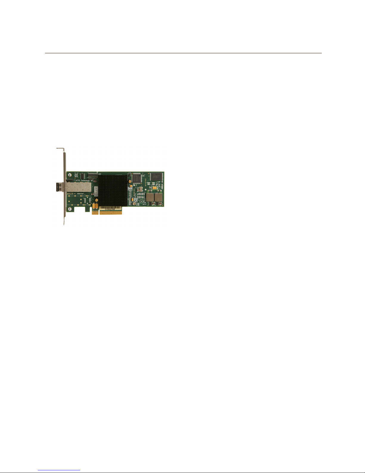
Adapter board details
Exhibit 3-10 FC-164E
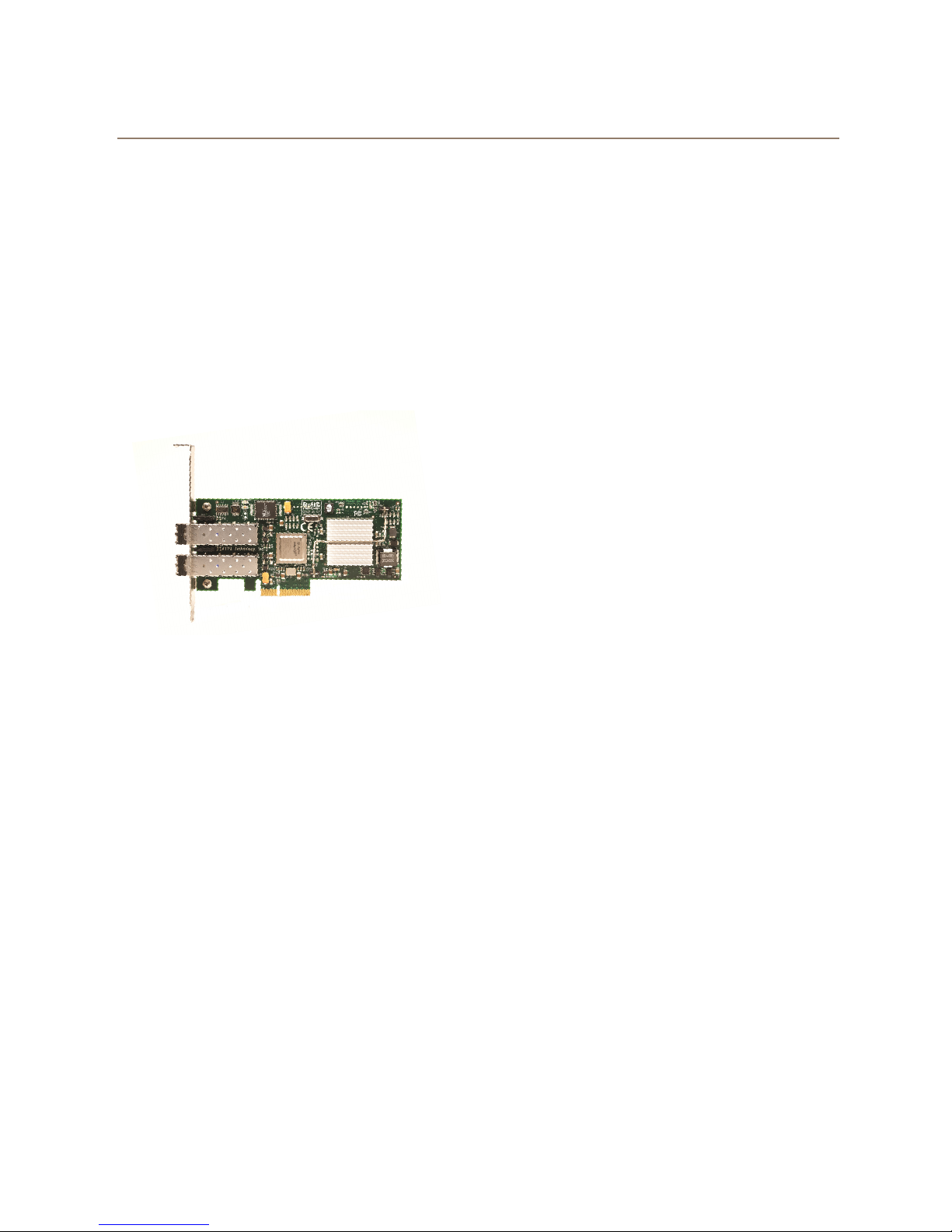
Exhibit 3-11 FC-162E
24 ATTO Technology Inc. Celerity FC Host Adapters Installation and Operation Manual
Page 29

Exhibit 3-12 FC-161E
Exhibit 3-13 FC-84EN
25
Page 30

Exhibit 3-14 FC-82EN
Exhibit 3-15 FC-81EN
26 ATTO Technology Inc. Celerity FC Host Adapters Installation and Operation Manual
Page 31

Exhibit 3-16 FC-44ES
FC controller
PCIe connector
SFP LC optical
connectors
Exhibit 3-17 FC-42ES
27
Page 32

Exhibit 3-18 FC-41ES
SFP LC optical
connector
PCIe connector
FC controller
28 ATTO Technology Inc. Celerity FC Host Adapters Installation and Operation Manual
Page 33

4 Updating Hardware Flash, Drivers
Your Celerity FC host adapter is shipped with the latest flash and drivers but these may need to be updated as
new versions become available. Visit the ATTO website,
flash bundle.
www.attotech.com
, to download the latest drivers and
Updating flash
Hardware flash memory may need to be updated as
new versions become available.
1 Download and install the most recent version of
the Configuration Tool from the ATTO
website. Refer to Updating the ATTO
Configuration Tool on this page.
2 Download the proper flash bundle (adapter
specific) from the ATTO website.
a. Go to www.attotech.com
b. Click on downloads.
c. Register or log in if previously registered.
d. Click on Fibre Channel Host Adapters in
the left dialog.
e. Navigate to your HBA model in the right
dialog and click on it.
f. Scroll down to and click the desired flash
bundle depending on the operating
system.
g. A download window appears. Choose
Save.
h. After the download has completed,
process the downloaded file:
• On OS X, mount the .dmg file.
• On Windows, extract the .zip file.
• On Linux, expand the .tgz file.
3 Launch the Configuration Tool.
4 In the Device window, select the adapter that
needs to be updated.
5 In the Flash window, click on the Browse
button to find the flash bundle that you
previously downloaded and extracted to your
desktop.
6 Click Update to update your flash ROM.
7 Repeat for any additional adapters installed in
the machine.
8 Reboot your system for the changes to take
effect.
Updating drivers
Update drivers by downloading the latest driver
software from the ATTO Technology website.
1Go to www.attotech.com
2 Click on downloads.
3 Register or log in if previously registered.
4 Click on Fibre Channel Host Adapters in the
left dialog.
5 Register or log in if previously registered.
6 Navigate to your HBA model in the right dialog
and click it.
7 Scroll down to and click the desired driver
depending on the operating system.
8 A download window appears. Choose Save.
9 After the download has completed, process the
downloaded file:
• On OS X, expand the .tgz file, then
double click on the installer icon.
• On Windows, run the downloaded .exe
file.
• On Linux, expand the .tgz file, then run
the install.sh installation script.
10 Follow the instructions for installing the drivers.
Updating the ATTO Configuration Tool
If you want the latest version of the ATTO
Configuration Tool, download it from the ATTO
website.
1Go to www.attotech.com.
2 Click on downloads.
3 Register or log in if previously registered.
4 Click on Fibre Channel Host Adapters in the
left dialog.
5 Register or log in if previously registered.
6 Navigate to your HBA model in the right dialog
and click it.
7 Scroll down to and click the desired ATTO
Configuration Tool depending on the
operating system.
8 A download window appears. Choose Save.
29
Page 34

9 After the download has completed, process the
downloaded file:
• On OS X, mount the .dmg file, then
double click on the installer icon located
in the new volume.
• On Windows, run the downloaded .exe
file.
• On Linux, expand the .tgz file, then run
the .bin installer application.
10 Follow the instructions for installing the
application.
11 To use the tool, refer to the ATTO Utilities
Installation and Operation Manual which may
be downloaded from the ATTO website.
a. Go to www.attotech.com.
b. Click on downloads.
c. Register or log in if previously registered.
d. Click on Fibre Channel Host Adapters in
the left dialog.
e. Navigate to your HBA model in the right
dialog and click it.
f. Click the Utility Manual (.pdf) link to
save/open the document.
30 ATTO Technology Inc. Celerity FC Host Adapters Installation and Operation Manual
Page 35

5 Troubleshooting
Note
Note
Note
Note
This chapter contains solutions for the most common problems you might encounter. If you need additional
assistance, please refer to the ATTO Technology website,
Technology representative.
General suggestions
www.attotech.com
, or contact an authorized ATTO
• Check each cable connection on every device.
• Verify all cables are in proper working condition.
Loose or broken cables are often the cause of
errors or problems.
Mac OS X
The Celerity FC supports Mac OS X versions
10.5.x and later.
1 Open the ATTO Configuration Tool from the
ATTO Utilities CD or download from the ATTO
website. Refer to the ATTO Utilities Installation
and Operation Manual for additional
information.
2 If the adapter does not appear in the Device
Listing, make sure it is properly seated in the
PCI slot.
a. Remove power from the PC.
b. Remove the case.
c. Check the PCI slot.
d. Replace the case.
e. Apply power.
• Check that Fibre Channel devices are plugged
into an AC outlet and are turned on before you
add power to your computer.
3 Verify the driver is loaded.
a. Click on the adapter name in the Device
Listing to view the Basic Info screen.
b. If the Driver Information section indicates
Unknown: driver not loaded, reinstall the
driver. Refer to Updating Hardware Flash,
Drivers on page 29.
c. If reinstalling the driver does not fix the
problem, contact an authorized ATTO
representative.
4 Reset the NVRAM for all channels to defaults
and reboot. If the problem persists, contact an
authorized ATTO representative.
When calling ATTO Technical Support,
please have a printout of the IOreg listing
and output from the Apple System Profiler
available.
If the Celerity adapter is properly seated and
devices are still not accessible, contact an
authorized ATTO representative.
Windows
The Celerity FC supports Windows versions
8, 7, Vista, XP; Server 2012, 2008, 2003 and
2000
• If the card has been recently re-flashed, a new
Windows driver must be installed. Follow the
procedure in Updating Hardware Flash, Drivers
on page 29.
• All of the external devices connected to the host
adapter should be identified. If they do not
appear in the Device Manager, the external
devices or connection may not be working
properly.
• For Intel-based PCs, check the computer CMOS
setup and verify that the PCI slots are configured
correctly.
• Procedures vary greatly: refer to the manual
supplied with your system or call the computer
supplier for configuration assistance.
31
Page 36

• Windows 8/7/Vista/XP/Server
Note
2012/2008/2003/2000 are Plug-n-Play
operating systems: be sure your computer’s
BIOS is set accordingly.
• If these do not solve the problem, re-flash the
host adapter and re-install the Windows
2000/XP/Server 2003/Vista/2008 driver. See
Updating Hardware Flash, Drivers
If the devices connected to the Celerity FC host
adapter are not accessible:
1 Click on the Start button
2 Click Control Panel. (In XP, 2000 and 2003,
click Settings then Control Panel.)
3 Double click on Administrative Tools.
4 Double click on Computer Management.
5Select Device Manager.
on page 29.
Linux
• If the Celerity FC host adapter does not appear
under the SCSI and RAID controllers, remove
power from the PC, open the case, and check
that the Celerity FC adapter is properly seated
in the PCI slot. Replace the case and apply
power.
• If the adapter has been identified but there is an
exclamation point (!) on the listing, right click on
the listing and select Uninstall.
6 Reload the driver (see Updating Hardware
Flash, Drivers on page 29).
7 Reboot the system and repeat the installation
process.
8 If problems persist, contact your authorized
ATTO Technology representative.
1 Verify the celerityfc driver is loaded with the
lsmod command. If lsmod does not show the
driver, refer to the installation instructions to
install and load the driver in Updating Hardware
Flash, Drivers on page 29.
2 Check the system log with the command
dmesg. The celerityfc driver creates status
messages during initialization. Make sure that
all installed cards are properly detected and
initialized.
VMware
1 After driver installation, please reboot host.
Once the host is back online, go to Storage and
create VMFS datastore. If storage does not
appear, perform a rescan using the VMware
3 Examine the contents of the file(s)
/proc/scsi/celerityfc/X, where X is the
adapter’s host number. This file contains details
such as link status, connection speed and
discovered devices.
Advanced users only. Modify the
makefile
Upon loading, the
detailed debugging information which may
help troubleshoot the problem.
Storage option. If your storage does not
present itself, thereafter, please contact your
SAN administrator.
to enable debugging information.
celerityfc driver
driver
displays
32 ATTO Technology Inc. Celerity FC Host Adapters Installation and Operation Manual
Page 37

Supplemental Guide for VMware ESX/ESXi
The following information should be used by advanced users only. Please consult with our Technical Support
Department before applying any of the following information.
1 Driver Configuration
Use the esxcfg-module command to query and
configure the ATTO adapter driver parameters. In
the examples that follow, <driver name> should be
replaced with the ATTO driver name.
To obtain a list of available driver parameters:
# esxcfg-module -i <driver name>
The following table lists the configurable parameters along with a brief description. Supported driver
abbreviations are: A - All drivers, C - celerityfc, celerity8fc, E - esashba, esas2hba.
PARAMETER DESCRIPTION
atto_log_mask
atto_max_sectors
can_queue
change_notification
cmd_per_lun
cmd_retry_count
event_log_mask
fab_alternate_exchanges
heap_initial Initial heap size allocated for the dirver. A
heap_max Maximum attainable heap size of the driver. A
io_time_out
max_logins
num_erq
Defines the log mask for sending ATTO driver
information to the system log. Default is 0 (none).
Maximum number of disk sectors in a single data
transfer. Default is 65535 (largest possible value).
Maximum number of commands per adapter
channel. Default is 128.
Enable notifying the OS of the arrival and departure
of target devices. Default is 1 (on).
Maximum number of commands per LUN. Default
is 16.
Maximum number of retries allowed for a
command. Default is 20.
A bit mask of events to report to the system log.
Default is 0x00000001 (crtitical events only).
Causes the chip to alternate between to exchanges
when it runs out of credits on a fabric. This may
improve performance in multiple initiator/target
environments. Default is 0 (off).
Time (in seconds) before an I/O command is timed
out by the driver. Set to 0 for no timeout. Default is
30.
Defines the maximum number of ports that can be
logged in at once. Default is 256.
Exchange Request Queue entries. In general, one
ERQ entry is required for each SEST entry. Default
is 256.
To list the driver parameters that have been set:
# esxcfg-module -g <driver name>
To set a driver parameter:
# esxcfg-module -s param=value <driver name>
Configuration changes made with the esxcfgmodule -s command are persistent across system
reboots. However, the changes will not take affect
until the system is rebooted.
Driver
Support
A
A
A
A
A
A
A
C
A
C
C
33
Page 38

Incoming Message Queue entries. These are used
num_imq
to report completion of I/O requests and to notify
the host driver of certain other kinds of events
detected by the hardware. Default is 256.
Number of SAS addresses to assign to the
num_sas_addr
adapter’s PHYs. Addresses are assigned
sequentially from the base address. Valid settings
are 1, 2, 4, 8. Default is 1.
Number of entries in the SCSI Exchange State
num_sest
Table. One of these structures is used per active
exhance. Default is 256.
num_sg_lists Number of SGL pages. Default is 256. A
num_targets Maximum number of target devices. Default is 256. E
old_device_reset
Use the old device reset method. Default is 0 (use
new method).
Maximum number of retries allowed for a port
port_retry_count
which is logged out. Default 0 (use NVRAM
setting).
private_els_timeout
quick_init
Timeout (in seconds) for ELS commands when on
a private loop. Default is 2.
Enabled quick link initialization. Default is 1
(enabled).
Maximum number of entries in a scatter/gather
sg_tablesize
table. A value of 255 means that the S/G table be
any size. Default is 255.
sgl_page_size
Scatter/Gather List page size in number of S/G
entries. Default is 128.
Override the NVRAM link speed setting. 0 for auto
speed_override
speed negotiation, 2 for 2Gb, 4 for 4Gb or 8 for
8Gb. Other values will cause the use of NVRAM
setting. Default is -1 (use NVRAM setting)
Override the NVRAM topology setting. 0 for loop, 1
topology_override
for PTP, 2 for loop preferred, 3 for PTP preferred.
Other values will cause the use of NVRAM setting.
Default is -1 (use NVRAM setting).
Wait for task management commands to complete
use_tm_completions
before returning from handler. Default is 1
(enabled).
use_transport_layer
Attached to the SCSI transport layer. Default is 1
(enabled).
C
E
C
A
C
C
C
A
A
C
C
A
A
34 ATTO Technology Inc. Celerity FC Host Adapters Installation and Operation Manual
Page 39

2 Adapter Management
On VMware ESX/ESXi you can identify and
manage ATTO adapters using the VMware
vSphere Client, or the Service Console. On ESXi,
the Service Console is referred to as Local Tech
Support Mode.
2.1 vSphere Client
With VMware vSphere Client, you can identify
ATTO adapters on a VMware ESX/ESXi system,
and view the attached storage devices.
1 Start vSphere Client from your local workstation
and select the host containing one or more
ATTO adapters.
2 Click the Configuration tab, and then select
Storage Adapters under Hardware in the left
pane.
3 A list of all storage adapters in the system is
displayed. The Model, Identifier (WWN or SAS
address) and Targets are shown for each
adapter channel.
A sample output is shown below:
~ # cat /proc/scsi/celerity8fc/6
ATTO Celerity 8GB Fibre Channel Adapter
Driver version 1.31
BIOS version 07/28/2010
Firmware version 06.01.00
Copyright 2001-2010
http://www.attotech.com
Driver Parameters:
-----------------quick_init=1, max_logins=256, speed_override=-1,
num_sest=256, num_imq=256, num_erq=256,
private_els_timeout=2, port_retry_count=0,
topology_override=-1,
fab_alternate_exchanges=0, sgl_page_size=128,
event_log_mask=0x00000001,
num_sg_lists=1024, cmd_per_lun=16,
can_queue=128, sg_tablesize=255,
atto_max_sectors=65535, cmd_retry_count=20,
io_time_out=30, change_notification=1,
old_device_reset=0, t10_dif=0
TBD - Insert a screenshot from vSphere client
showing ATTO adapter
2.2 Service Console
Using the Service Console, information about each
adapter channel can be found in the /proc/scsi
filesystem, under /proc/scsi/<driver name>.
To view details on a specific adapter channel, run
the following command:
# cat /proc/scsi/<driver name>/<channel>
This command displays the following information:
"Adapter type
"Driver, BIOS and Firmware versions
"Driver Parameters
"Adapter Model and Identifier (WWN or SAS
address)
"Virtual Port Information
"Discovered Targets
"Driver Statistics
Adapter Information:
-------------------Model: ATTO Celerity FC-82EN
WWNN: 20000010:8601dfb0
WWPN: 21000010:8601dfb0
Link down
Virtual Port Information (NPIV): Max VPorts:16
Max VLogins:32
-----------------------------------------------------------------
Discovered Ports:
# TargID PortWWN PortId I T
----------------------------------------------None
Statistics:
----------Time elapsed (ms) : 95353655
Commands completed : 0
Outstanding commands : 0
Max outstanding commands: 0
35
Page 40

Virtual Ports (NPIV)
Note
N_Port ID Virtualization (NPIV) is an extension to
the Fibre Channel industry standard. NPIV allows a
single, physical adapter port to function as multiple
virtual ports (VPorts), each having a unique Fibre
Channel World-Wide-Name in the SAN. This allows
a Storage Administrator to follow SAN best
practices, such as zoning and masking, to control
LUN access on a per-VPort basis.
Support for NPIV is included in the ATTO 8Gb and
16Gb Celerity drivers available for both Windows
and VMware ESX/ESXi. The following sub-sections
contain an overview of the NPIV functionality
provided on each platform.
a
Name
NpivEnable
MaxNpivVPorts
TargetMode
a.The Default Value is the value assigned to the parameter when it is not explicitly defined in the registry.
Default Value
0 0, non-0
81-8
0 0, non-0
Range
1 Windows
NPIV support for Windows is currently
limited to Windows Server 2008 R2 and
Hyper-V R2.
The 8Gb and 16Gb Celerity drivers for Windows
provide NPIV support compatible with Microsoft's
Hyper-V virtualization platform. Each physical port on
the adapter is capable of supporting up to eight virtual
ports. NPIV functionality is disabled by default and
must be enabled via the Windows registry (refer to the
“Registry Settings” section of the readme.html file in
the ATTO install directory for details on modifying HBA
registry parameters). The following registry values are
applicable to NPIV:
Usage
A non-zero value enables the NPIV functionality in the
driver. A zero value disables NPIV.
Sets the maximum number of virtual ports that can be
created on each physical port in the adapter. Setting
this parameter to a value outside the stated range will
cause the driver to revert to the default value (note that
zero is not a valid value).
A non-zero value enables the Target Mode functionality
in the driver. This parameter must be either undefined
or set to zero for the NPIV functionality to be enabled.
As mentioned above, NPIV functionality is not
compatible with the existing Target Mode
capabilities of the Windows driver. As such, Target
Mode must be disabled in order for NPIV to be
successfully enabled. Attempting to enable both
Target Mode and NPIV will enable Target Mode, but
disable NPIV, causing a Warning message (Event
ID 32818) to be posted to the Windows Event Log.
36 ATTO Technology Inc. Celerity FC Host Adapters Installation and Operation Manual
For Hyper-V, virtual ports need to be explicitly
created before they can be used by a virtual
machine. The creation and management of virtual
ports is a function of the ATTO Configuration Tool.
Please refer to the ATTO Utilities Installation and
Operation Manual for details on using the
ConfigTool to manage virtual ports.
For additional information about utilizing NPIV in a
Hyper-V environment refer to TechNet topic
“Configuring a SAN Environment for VMM”
(http://technet.microsoft.com/en-
us/library/cc764269.aspx).
Page 41

2 VMware ESX/EXi
The 8Gb and 16Gb Celerity drivers for VMware
ESX/ESXI 4.x and VMware ESXI 5.x provide NPIV
support by default (the functionality does not have to
be explicitly enabled). However, there are four driver
parameters that affect the performance and behavior
of the NPIV feature, they are as follows:
max_npiv_logins
max_npiv_vports
npiv_disc_wait_time
npiv_init_retries
The maximum number of target ports that can be logged into a virtual port.
Default is 32; maximum is 256.
The maximum number of virtual ports for an adapter channel. The default is 16;
maximum is 64
The time period (in ms) that the driver waits for discovery to complete after
creating a virtual port. Default is 10000.
The number of times to attempt to initialize a virtual port before giving up.
Default is 10.
Information about the VPorts is shown in the Driver
info file on the Service Console. Refer to the
Supplemental Guide for VMware ESX/ESXi in this
chapter for details on viewing or modifying the above
values.
Virtual ports are created by the kernel when an
associated VM is started, and deleted when the VM is
stopped. Active virtual ports will appear as additional
Virtual Adapters in the vSphere client.
For additional NPIV configuration details, please
consult the VMware Fibre Channel SAN Configuration
Guide
(
http://www.vmware.com/pdf/vsphere4/r41/vsp_41
_san_cfg.pdf
).
37
Page 42

Appendix A Glossary
Some terms used in the Fibre Channel industry are defined below. More information is available through the ATTO
Technology website (
Cern (
www.cern.ch
Consortium (
Term Definition
ANSI American National Standards Institute
arbitrate process of selecting one L_Port from a collection of ports which ask for use of the arbitrated loop
arbitrated loop a loop topology (FC-AL) in which two or more ports are interconnected, but only two ports can
auto negotiation hardware senses and automatically responds depending on configuration
BER Bit Error Rate: a measure of transmission accuracy; the ratio of bits received in error to bits sent
bit smallest unit of data a computer can process: a single binary digit with a value of either 0 or 1
bus a collection of unbroken signal lines used to transmit information from one part of a computer
byte an ordered set of 8 bits
channel a point-to-point link which transports data from one point to another
CPU Central Processing Unit: the portion of the computer that actually performs computations
CRC Cyclic Redundancy Check: an error-correcting code which calculates a numeric value for received
destination
address
device driver a program that allows a microprocessor to direct the operation of a peripheral device
DMA Direct Memory Access: a way to move data from a storage device directly to RAM without using
DMA bus master allows a peripheral to control the flow of data to and from system memory by block as opposed to
fabric a Fibre Channel switch of two or more Fibre Channel switches interconnected to physically transmit
FC Fibre Channel
F_port a port in the Fibre Channel fabric where a N_port may attach
FL_port a port in the Fibre Channel fabric where a NL_port may attach in an arbitrated loop
frame an indivisible unit for transfer of information in Fibre Channel
frame header the first field in the frame containing the address and other control information about the frame
full-duplex a communication protocol which allows transmission in both directions at the same time
half duplex a communication protocol which allows transmission in both directions, but only one direction at a
host a processor, usually a CPU and memory, which communicates with devices over an interface
initiator device a component which originates a command
L_port a port in an arbitrated loop, either a NL_port or a FL_port
LED Light-emitting diode: a type of diode that emits light when current passes through it; visible LEDs
LUN Logical Unit Number: an identifier for a logical unit (0-7)
multi-mode fiber an optical fiber which can carry several beams of light at once
www.iol.unh.edu/consortiums
www.attotech.com
), the Storage Area Networking Industry Association (
at the same time
communicate at one time; low-cost solution which may or may not use hubs and switches
system to another; taps on the lines connect devices to the bus
and transmitted data; if no error has occurred during transmission, the CRC for both received and
transmitted data should be the same
a value in the frame header of each frame which identifies the port in the node where the frame is
being sent
the CPU’s resources
allowing the processor to control the data by bytes (PIO or programmed I/O)
data between any two N_Ports on the switch or switches
time
are used as indicator lights on all sorts of electronic devices
), the Fibre Channel Industry Association (
www.snia.org
, click on FC).
www.fibrechannel.com
), and the Fibre Channel
),
i ATTO Technology Inc. Celerity FC Host Adapters Installation and Operation Manual
Page 43

Term Definition
N_port a port attached to a node used with point to point or fabric configurations
NL_ port a port attached to a node in Fibre Channel arbitrated loop or fabric loop configuration
originator an initiating device; a component which originates a command
parity checking a method which verifies the accuracy of data transmitted over the SCSI bus by adding one bit in
the transfer to make the sum of all the bits either odd or even (for odd or even parity); an error
message occurs if the sum is not correct
PCI Peripheral Component Interconnect. Allows peripherals to be connected directly to computer
memory, bypassing the slower ISA and EISA busses
point-to-point a topology where two ports communicate
port an access point in a device: see N_port, NL_port, etc.
port address also port number; the address, assigned by the PCI bus, through which commands are sent to a
host adapter board
port number see port address
receiver the ultimate destination of data transmission; a terminal device
SAS Serial Attached SCSI: a serial SCSI bus technology and point to point architecture for connecting
host bus adapters to storage devices
SATA Serial AT Attachment: a serial ATA bus technology and point to point architecture for connecting
host bus adapters to storage devices
scatter/gather a device driver feature which allows the host adapter to modify a transfer data pointer so that a
single host adapter can access many segments of memory, minimizing interrupts and transfer
overhead
SCSI Small Computer Systems Interface: a processor-independent standard for system-level interface
between a computer and intelligent devices including hard disks, floppy disks, CD-ROM, printers,
scanners, etc.
single-mode fiber an optical fiber with a small core which supports one wavelength (ray of light); the core radius is
nearly equal to the wavelength of the source
SNMP Simple Network Management Protocol: a standard for monitoring network-attached devices
topology logical layout of the parts of a computer system or network and their interconnections
transceiver a transmitter/receiver module
transfer rate the rate at which bytes or bits are transferred, as in megabytes or gigabits per second
ii
Page 44

Appendix B Accessories
The following Fibre Channel accessories are available through ATTO Technology and authorized resellers.
Contact an ATTO Technology authorized sales representative to order.
Optical Cables
CBL-FCFI-05x5 m. cable– Duplex 50 Micron Multi-mode FC/Optical
CBL-LCSC-0033 m. 50/125 optical cable (LC to SC)
CBL-LCSC-01010 m. 50/125 optical cable (LC to SC)
SFPX-000 10Gb/s Ethernet SFP+ LC SW Optical
SFP8-000 8Gb/s SFP+ LC SW Optical
SFP4-000 4Gb/s SFP LC SW Optical
A variety of iSCSI, Fibre Channel, SAS and SCSI products are also available from ATTO Technology. Please
contact your ATTO sales representative for product descriptions and part number information.
Fibre Channel and iSCSI solutions
ATTO FibreBridgeTMFibre Channel-to-SCSI bridge
ATTO iPBridge iSCSI to SCSI, iSCSI to Fibre Channel bridges
SCSI solutions
ATTO ExpressPCI Family of SCSI Host Adapters (see Appendix C)
SAS/SATA Solutions
ATTO ExpressSAS family of SAS Adapters (see Appendix C)
FastFrame solution
ATTO FastFrame Family of 10Gb Ethernet Network Interface Cards
ATTO FastFrame Family of 10Gb Ethernet Converged Network Adapters
Software
ATTO Utilities Configuration and management software
ATTO Express Power Center Windows & Mac OS X RAID 0 and benchmark software
(see Appendix C)
(see Appendix C)
iii ATTO Technology Inc. Celerity FC Host Adapters Installation and Operation Manual
Page 45

Appendix C ATTO Adapter Selection Guides
Contact your ATTO representative or visit the ATTO website for details on all ATTO products.
ExpressPCI SCSI host adapters
Ultra 320 SCSI
Product Features
Max. transfer rate (MB/sec.) 640 640 640
Low Voltage Differential
Single-ended SCSI
Number of SCSI Channels (internal/external) 2/2 0/2 2/2
Number of SCSI IDs supported 30 30 30
Low profile
Large file transfers
Cable distances (m) 12.5 12.5 12.5
32-bit PCI compatible
64-bit PCI compatible
33 MHZ PCI
133 MHZ PCI-X
66 MHz PCI
x4 PCI Express
Windows 2000/XP, Server 2003/2008/Vista support
Linux support
Mac OS X support
Novell Netware support
RoHS compliant
UL5D UL5D LP UL4D
• • •
• • •
•
• • •
•
•
•
•
•
• •
• • •
• • •
• • •
• • •
• • •
iv
Page 46

ExpressSAS 6 Gb Host adapters
Product
Features
Max Data Rate 6 Gb/sec. 6 Gb/sec. 6 Gb/sec. 6 Gb/sec. 6 Gb/sec.
x8 PCI Express • • • • •
Number of ports 16 16 8 8 8
Port configuration
external/internal
Connector type
Number of devices
supported
1.5 Gb SATA
support
3 Gb SATA II
support
3 Gb SAS support • • • • •
6 Gb SATA II
support
6 Gb SAS support • • • • •
Software RAID00000
Cable distances
Advanced Data
Streaming™
32-bit support • • • • •
64-bit support • • • • •
Windows • • • • •
Linux • • • • •
Mac OS X • • • • •
VMware • • • • •
Low profile • • 1/2 height 1/2 height 1/2 height
H6F0 H60F H680 H608 H644
16/0 0/16 8/0 0/8 4/4
4 mini SAS (x4)
SFF-8088
external
512 end-point
devices
• • • • •
• • • • •
• • • • •
up to 8m SAS, 1m
SATA
• • • • •
4 mini SAS (x4)
SFF-8087 internal
512 end-point
devices
up to 8m SAS, 1m
SATA
2 mini SAS (x4)
SFF-8088
external
256 end-point
devices
up to 8m SAS, 1m
SATA
2 mini SAS (x4)
SFF-8087 internal
256 end-point
devices
up to 8m SAS, 1m
SATA
1 mini SAS (x4)
SFF-8088
external
1 mini SAS (x4)
SFF-8087 internal
256 end-point
devices
up to 8m SAS, 1m
SATA
v ATTO Technology Inc. Celerity FC Host Adapters Installation and Operation Manual
Page 47

ExpressSAS 6 Gb RAID adapters
Product
Features
Max Data Rate 6 Gb/sec. 6 Gb/sec. 6 Gb/sec. 6 Gb/sec.
x8 PCI Express • • • •
Number of ports 16 8 8 8
Port configuration
external/internal
Connector type
Number of devices
supported
1.5 Gb SATA
support
3 Gb SATA II
support
3 Gb SAS support • • • •
6 Gb SATA II
support
6 Gb SAS support • • • •
Software RAID 0, 40, 50, 60 0, 40, 50, 60 0, 40, 50, 60 0, 40, 50, 60
Integrated RAID
RAID Management
Utility
Global Hot Spares • • • •
Event notification E-mail, pop-up, log file E-mail, pop-up, log file E-mail, pop-up, log file E-mail, pop-up, log file
SNMP • • • •
Memory (ECC) 512 MB 512 MB 512 MB 512 MB
Cable distances
Advanced Data
Streaming™
32-bit support • • • •
64-bit support • • • •
Windows • • • •
Linux • • • •
Mac OS X • • • •
VMware
Low profile • • • •
128 SAS/SATA targets
R60F R680 R608 R644
0/16 8/0 0/8 4/4
4 mini SAS (x4) SFF-
8087 internal
• • • •
• • • •
• • • •
0, 1, 4, 5, 6
JBOD, DVRAID
• • • •
up to 10m SAS, 1m
SATA
• • • •
2 mini SAS (x4) SFF-
8088 external
128 SAS/SATA targets
0, 1, 4, 5, 6
JBOD, DVRAID
up to 10 SAS, 1m
SATA
2 mini SAS (x4) SFF-
8087 internal
128 SAS/SATA targets 128 SAS/SATA targets
0, 1, 4, 5, 6
JBOD, DVRAID
up to 10m SAS, 1m
SATA
1 mini SAS (x4) SFF-
8088 external
1 mini SAS (x4) SFF-
8087 internal
0, 1, 4, 5, 6
JBOD, DVRAID
up to 10m SAS, 1m
SATA
vi
Page 48

FastFrame SFP+ Network Interface Cards
Product
Features
Max Data Rate 10 Gb/sec. 10 Gb/sec. 10 Gb/sec.
x8 PCI Express • • •
Number of ports 4 2 1
Connector type LC Fibre Optic LC Fibre Optic LC Fibre Optic
Advanced Data
Streaming™
32-bit support • • •
64-bit support • • •
Windows • • •
Linux • • •
Mac OS X • • •
Low profile • •
NS14 NS12 NS11
• • •
FastFrame 10GBASE-T Network Interface Cards
Product
Features
Max Data Rate 10 Gb/sec. 10 Gb/sec.
x8 PCI Express • •
Number of ports 2 1
Connector type RJ45 RJ45
Advanced Data
Streaming™
32-bit support • •
64-bit support • •
Windows • •
Linux • •
Mac OS X • •
Low profile • •
NT12 NT11
• •
vii ATTO Technology Inc. Celerity FC Host Adapters Installation and Operation Manual
Page 49

FastFrame SFP+ Converged Network Adapters
Product
Features
Max Data Rate 10 Gb/sec. 10 Gb/sec. 10 Gb/sec.
x8 PCI Express • • •
Number of ports 4 2 1
Connector type LC Fibre Optic LC Fibre Optic LC Fibre Optic
Advanced Data
Streaming™
FCoE Support • • •
32-bit support • • •
64-bit support • • •
Windows • • •
Linux • • •
Mac OS X • • •
Low profile • •
CS14 CS12 CS11
• • •
viii
Page 50

Appendix D Standards, Compliances: 16Gb adapters
The Technical Specification sheet for each Celerity FC host adapter lists certifications for that model. Models
covered by this page include the Celerity FC-164E, FC-162E and FC-161E.
FCC standards: radio and television interference
This equipment has been tested and found to comply with the limits for a Class B
digital device, pursuant to Part 15 of the FCC Rules. These limits are designed to
provide reasonable protection against harmful interference in a residential
installation. This equipment generates, uses, and can radiate radio frequency
energy and, if not installed and used in accordance with the instruction manual,
may cause interference to radio communications. However, there is no guarantee that interference will not occur
in a particular installation. If this equipment does cause interference to radio or television reception, which can be
determined by turning the equipment off and on, the user is encouraged to try to correct the interference by one
or more of the following measures:
• Reorient or relocate the receiving antenna
• Increase the separation between the equipment and receiver
• Connect the equipment into an outlet on a circuit different from that to which the receiver is connected
• Consult the dealer or an experienced radio/TV technician for help
Canadian standards
This Class A digital apparatus complies with Canadian ICES-003.
Cet appareil numérique de la classe A est conforme à la norme NMB-003 du Canada.
European standards
Declaration of Conformity
This following statement applies to the Celerity FC host adapter.
This device has been tested in the basic operating configuration and found to be compliant with
the following European Union standards: Application of Council Directive: 89/336/EEC
Standard(s) to which conformity is declared: EN55024:2002; EN55022:2002 CLASS B.
This Declaration will only be valid when this product is used in conjunction with other CE
approved devices and when the entire system is tested to the applicable CE standards and found to be compliant.
Some ATTO Celerity cards comply with Directive 2011/65/EU on the Restriction of the Use
of Hazardous Substances in Electrical and Electronic Equipment (RoHS). Contact your
ATTO representative regarding RoHS compliant products.
ix ATTO Technology Inc. Celerity FC Host Adapters Installation and Operation Manual
Page 51

Appendix E Standards, Compliances: 8Gb adapters
The Technical Specification sheet for each Celerity FC host adapter lists certifications for that model. Models
covered by this page include the Celerity FC-84EN, FC-82EN and FC-81EN.
FCC standards: radio and television interference
This equipment has been tested and found to comply with the limits for a Class B
digital device, pursuant to Part 15 of the FCC Rules. These limits are designed to
provide reasonable protection against harmful interference in a residential
installation. This equipment generates, uses, and can radiate radio frequency
energy and, if not installed and used in accordance with the instruction manual,
may cause interference to radio communications. However, there is no guarantee that interference will not occur
in a particular installation. If this equipment does cause interference to radio or television reception, which can be
determined by turning the equipment off and on, the user is encouraged to try to correct the interference by one
or more of the following measures:
• Reorient or relocate the receiving antenna
• Increase the separation between the equipment and receiver
• Connect the equipment into an outlet on a circuit different from that to which the receiver is connected
• Consult the dealer or an experienced radio/TV technician for help
Canadian standards
This Class A digital apparatus complies with Canadian ICES-003.
Cet appareil numérique de la classe A est conforme à la norme NMB-003 du Canada.
European standards
Declaration of Conformity
This following statement applies to the Celerity FC host adapter.
This device has been tested in the basic operating configuration and found to be compliant with
the following European Union standards: Application of Council Directive: 89/336/EEC
Standard(s) to which conformity is declared: EN55024:2002; EN55022:2002 CLASS B (82EN &
81EN), EN55022:2002 CLASS A (84EN).
This Declaration will only be valid when this product is used in conjunction with other CE approved devices and
when the entire system is tested to the applicable CE standards and found to be compliant.
Some ATTO Celerity cards comply with Directive 2002/95/EC on the Restriction of the Use
of Hazardous Substances in Electrical and Electronic Equipment (RoHS). Contact your
ATTO representative regarding RoHS compliant products.
x
Page 52

Appendix F Standards, Compliances: 4Gb adapters
The Technical Specification sheet for each Celerity FC host adapter lists certifications for that model. Models
covered by this page include the Celerity FC-44ES, FC-42ES, FC-41ES and FC-41XS.
FCC standards: radio and television interference
This equipment has been tested and found to comply with the limits for a Class B
digital device, pursuant to Part 15 of the FCC Rules. These limits are designed to
provide reasonable protection against harmful interference in a residential
installation. This equipment generates, uses, and can radiate radio frequency
energy and, if not installed and used in accordance with the instruction manual,
may cause interference to radio communications. However, there is no guarantee that interference will not occur
in a particular installation. If this equipment does cause interference to radio or television reception, which can be
determined by turning the equipment off and on, the user is encouraged to try to correct the interference by one
or more of the following measures:
• Reorient or relocate the receiving antenna
• Increase the separation between the equipment and receiver
• Connect the equipment into an outlet on a circuit different from that to which the receiver is connected
• Consult the dealer or an experienced radio/TV technician for help
Canadian standards
This Class B digital apparatus complies with Canadian ICES-003.
Cet appareil numérique de la classe B est conforme à la norme NMB-003 du Canada.
European standards
Declaration of Conformity
This following statement applies to the Celerity FC host adapter.
This device has been tested in the basic operating configuration and found to be compliant with
the following European Union standards: Application of Council Directive: 89/336/EEC
Standard(s) to which conformity is declared: EN55024:2002; EN55022:2002 CLASS B.
This Declaration will only be valid when this product is used in conjunction with other CE
approved devices and when the entire system is tested to the applicable CE standards and found to be compliant.
Some ATTO Celerity cards comply with Directive 2002/95/EC on the Restriction of the Use
of Hazardous Substances in Electrical and Electronic Equipment (RoHS). Contact your
ATTO representative regarding RoHS compliant products.
xi ATTO Technology Inc. Celerity FC Host Adapters Installation and Operation Manual
Page 53

Appendix G Safety, Warranty
All ATTO host adapter products have been tested to meet applicable safety standards when operated in proper
electrical and thermal environments.
Safety
Please review the specifications for your specific host adapter before installing and operating it in any computer
system to ensure compatibility.
Installation
Before installing an ATTO host adapter product into your computer system, unplug the computer from its electrical
power source and allow adequate time for electrical discharge and the internal components to cool down before
removing the computer system cover. This will decrease the risk of personal injury from electrical shock or
touching the hot surface of an electrical component.
Once an ATTO host adapter is installed in a computer system, the computer cover must be reinstalled properly
before turning the computer system back on.
Operation
ATTO host adapters require adequate cooling to function properly. If you have any questions as to the airflow
provided by your computer system, please refer to your computer system manual or contact your computer
system manufacturer.
To facilitate proper air circulation, ATTO host adapters should never be operated in a computer system without
the cover installed or with an inoperable fan as this may cause safety or thermal problems which could damage
the ATTO host adapter and void the warranty.
ATTO Technology, Inc. limited warranty
ATTO Technology, Inc. warrants to the original purchaser of this product that it is free from defects in material and
workmanship as described in the ATTO Technology website,
ATTO Technology, Inc. liability shall be limited to replacing or repairing, at its option, any defective product. There
is no charge for parts or labor should ATTO Technology, Inc. determine that this product is defective.
Products which have been subject to abuse, misuse, alteration, neglected, or have been serviced, repaired or
installed by unauthorized personnel shall not be covered under this warranty provision. Damage resulting from
incorrect connection or an inappropriate application of this product shall not be the responsibility of ATTO
Technology, Inc. Liability is limited to ATTO Technology, Inc.product(s); damage to other equipment connected to
ATTO Technology, Inc.product(s) is the customer’s responsibility.
This warranty is made in lieu of any other warranty, express or implied. ATTO Technology, Inc. disclaims any
implied warranties of merchantability or fitness for a particular purpose.
ATTO Technology, Inc. responsibility to repair or replace a defective product is the sole and exclusive remedy
provided to the customer for breech of this warranty. ATTO Technology, Inc. is not liable for any indirect, special,
incidental, or consequential damages irrespective of whether ATTO Technology, Inc. has advance notice of the
possibility of such damages.
No ATTO Technology, Inc. dealer, agent or employee is authorized to make any modification, extension or
addition to this warranty.
www.attotech.com
, for three years.
xii
 Loading...