

ATTO Technology FastStream SC 5500E, FastStream SC 7500E, FastStream SC 8500E Installation And Operation Manual
Page 1

ATTO FastStream
Embedded Storage Controller
Installation and Operation Manual
Fibre Channel to SAS/SATA Models
SC 5500E
SC 7500E
SC 8500E
Page 2

ATTO Technology, Inc.
155 CrossPoint Parkway
Amherst, New York 14068 USA
www.attotech.com
Tel (716) 691-1999
Fax (716) 691-9353
Sales support: sls@attotech.com
Technical support: Monday -- Friday, 8am-8pm EST
techsupp@attotech.com
© 2009 A TT O Technology, Inc. All right s reserved. All brand or product names are trademarks of their respective
holders. No part of this manual may be reproduced in any form or by any means without the express written
permission of ATTO Technology, Inc.
1/2009 PRMA-0395-000
Page 3

Contents
1.0 ATTO FastStream Offers Data Protection ...................................................1
Technical features
System memory
Expansion slot
RAID protection features
Audio/video features
1.1 ATTO FastStream Embedded Components .....................................2
Board dimensions
Temperature
Humidity
Altitude
ESD
Real Time Clock
Power supply requirements
SAS/SATA ports
Fibre Channel ports
Management ports
Manual reset switch
LED
1.2 ATTO Celerity FC42-ES Host Adapter ...............................................4
Hardware specifications
Advanced FC capabilities
Host bus specifications
External connectivity
1.3 ATTO Celerity FC44-ES Host Adapter ...............................................6
Hardware specifications
Advanced FC capabilities
Host bus specifications
External connectivity
1.4 ATTO Celerity FC84-EN Host Adapter ...............................................8
Technical specifications
Advanced FC capabilities
Host bus specifications
Environmental & physical specifications
External connectivity
Software specifications
2.0 Install the FastStream ....................................................................................10
Unpacking the packing box; verifying contents
Installing the FastStream
Discovering the IP address
Setting up Internet Explorer
Beginning initial configuration
3.0 Ensure Drive Integrity ....................................................................................14
Before creating RAID groups
After creating RAID groups
4.0 Configure Storage into RAID Groups ..........................................................16
Page 4

Features you may choose
Auto-Rebuild
Fault Tolerance
Initialization
Selecting an application
Preliminary steps
Quick Digital Video
Audio
General Digital Video, General IT or Database
Creating a custom setup
5.0 Modify System Values ...................................................................................21
Changing current user name, password
Creating a read-only user name, password
Changing system variables
6.0 Monitor Storage, Configurations ..................................................................23
Health and Status Monitor page
Configuration Display page
SCSI Enclosure Services (SES)
6.1 Remote System Monitoring ................................................................25
Types of errors
Warning messages
Message severity levels
Email notification
6.2 Drive Diagnostics ................................................................................27
Preliminary steps
Read-only Drive Test
Drive performance and health
Identifying a drive attached to the FastStream
6.3 SCSI Enclosure Services (SES) .........................................................29
Setting up SES
Identifying SES elements
Monitoring SES elements
Use the Health and Status Monitor
Use the Manage menu
7.0 Modify Storage ...............................................................................................34
Preliminary steps
RAID group processes
Creating RAID groups
Deleting RAID groups
Adding drives to a RAID group
Adding mirrors to a RAID configuration
Changing RAID configuration: RAID migration
Modifying RAID group mapping
Modifying RAID group partitions
Rebuilding RAID groups
Modifying RAID options
FastStream process: adding or removing Hot Spares
Removing RAID configuration data
Advanced CLI page
Page 5

8.0 Manage ATTO Devices, Configurations .......................................................39
Creating a unique name for your FastStream
Discovering, managing other ATTO devices
Saving or restoring a configuration
9.0 Interface Options ...........................................................................................41
Using the ExpressNAV Storage Manager
Using the serial port
Using Telnet
10.0 Update Firmware ..........................................................................................43
Appendix A CLI Provides an ASCII-based Interface ..........................................i
CLI error messages
CLI summary
CLI command explanations
Appendix B Design RAID Groups .......................................................................xvii
JBOD: Just a Bunch of Disks
DVRAID: Digital Video RAID
RAID Level 0: striping, no redundancy
RAID Level 1: mirroring (duplicate drives)
RAID Level 1 plus additional mirroring
RAID Level 1+0: striping, mirror spans two drives
RAID Level 4: striping, one parity drive
RAID Level 5: striping, parity distributed among drives
RAID Level 6: striping, two parity blocks distributed among drives
Appendix C Multipathing ......................................................................................xxi
Setup of the FastStream with Multipathing
Improved Availability of Storage with improved performance
Load Balancing algorithms for OS X and Windows DSM MPIO
Appendix D Standards and Compliances ...........................................................xxii
FCC Standards: Radio and Television Interference
Canadian Standards
European Standards
Declaration of Conformity
Appendix E Warranty ............................................................................................xxiii
Appendix F Reference Charts ..............................................................................xxiv
Generated frequencies
Data rate in cables
Connector pinouts
ATX 24-pin power connector pinouts (J1)
RJ-11 connection pinouts (J3)
Internal SAS 4i connector pinouts (J9)
RJ-45 connector pinouts (J2)
Internal SAS 4i connector pinouts (J11)
Jumpers pinouts
ATX power switch header pinouts (P3)
Page 6

1.0 ATTO FastStream Offers Data Protection
The A TTO FastS tream SC 5500E, 7500E and 8500E provide blazing-fast performance and RAID protection in an
embeddable ATX form factor.
With 4 Gigabit per second (Gb/sec.) Fibre Channel
host connections and 3 Gb/sec. SAS drive
connections, the ATTO FastStream provides
unprecedented flexibility while adding RAID protection
without compromising performance.
ATTO FastStream Embeddable Storage Controllers
are high performance RAID storage devices which can
be seamlessly integrated into an ATX enclosure.
ATTO FastStream FC to SAS RAID controllers are
ideally suited for bandwidth intensive applications
such as digital film, video and audio as well as medical
imaging, digital prepress and disk to disk backup.
While RAID improves data accessibility and reliability
during normal operations, you still need a good
backup strategy for long-term protection of your data.
Technical features
• MicroATX form factor: conforms to industrystandard MicroATX form factor specification for
board size, board mounting locations and
expansion slot placement.
• Intel 81348 processor
• 8 independent SAS/SATA ports
• SC 7500 supports up to 128 disk drives
• SC 5500 supports up to 64 disk drives
• Internal wide-SAS Small Form Factor (SFF)
8484 connectors
• Optional external (x4) miniSAS SFF8080
connector for JBOD expansion
• SES (SCSI Enclosure Services)
• RS-232 management port with a back panel
accessible RJ11 interface
• 10/100/1000 Megabits per second (Mb/sec.)
Ethernet management port with an RJ45
connector and integrated LEDs
• 8 MB Flash
• LED status for link and speed
• Manual reset switch to reboot the Storage
Controller
• Battery-backed event log asynchronous SRAM
• System monitoring hardware
• Real time clock
• SCSI Enclosure Services (SES)
System memory
• One 240-pin DDR2 SDRAM DIMM connector
• Supports 512 MB of unbuffered, ECC DDR2-533
SDRAM DIMM
• Qualified DIMM: Kingston Technology
KVR533D2E4/512; RoHS compliant
Expansion slot
• One PCIe expansion slot, x8 electrical and
mechanical widths aligned with expansion slot 7
of the standard ATX form factor
• Conforms to the PCIe Base 1.0a and CEM
specifications
• Accepts either a 2- or 4-port 4 or 8-Gb Celerity
PCIe Host Adapter as the host port interface
• Host adapter is oriented perpendicular to the
FastStream SC board and can be mounted
parallel with a 90
º
angle adapter
RAID protection features
• Hardware DVRAID, RAID Level 0, 1, 4, 5, 6,1+0
and JBOD, all user configurable
• N-way mirroring
• Global Hot Spares to ensure continuous
operation if a drive fails. The Hot Spare
automatically comes on-line and rebuild starts if
a disk failure is detected
• Automatic rebuild of RAID groups and
changeable Rebuild Priority keep the system
operational if a drive fails
• Support for large LBAs (64-bit operating
systems), partitions, partial data transfer to
improve performance and minimizes memory
use, and spanning
Audio/video features
• DVRAID provides performance for up to 22
streams of SD video or 6 streams of 10-bit
uncompressed HD video.
• Support for video on demand
• Support for multiple streams of audio
1
ATTO Technology Inc. FastStream SC RAID Controller Installation and Operation Manual
Page 7

1.1 ATTO FastStream Embedded Components
The A TTO FastStream Fibre Channel to SAS/SATA RAID controller line can be seamlessly integrated into an A TX
or custom storage enclosure.
ATTO FastStream SC RAID controllers support nextgeneration media and are equipped to handle the
throughputs needed by advanced disk technologies.
For installation instructions, refer to
FastStream
on page 10.
Install the
Board dimensions
The FastStream SC embedded storage controllers
feature MicroATX-size printed circuit boards (PCB).
The boards can be used in enclosures that have
adequate clearance for the DIMM socket and
allowance for connecting to internal connectors.
Width:
Length:
Height:
7.0 in. ± 0.005 in. (17.78 cm ±0.01 cm)
9.6 in. ± 0.005 in. (24.38 cm ±0.01 cm)
1.3 in. ± 0.005 in. (3.3 cm ±0.01 cm)
Temperature
Non-operating:
Operating:
-40 ºC to +70 ºC
+5 ºC to +40 ºC
Humidity
Non-operating:
Operating:
5% to 95% non-condensing
10% to 90% non-condensing
Altitude
Non-operating:
Operating:
50,000 feet (15,240 meters)
10,000 feet (3048 meters)
ESD
Contact discharge:
Air discharge:
Up to ±8kV no errors
Up to ±15kV no errors
Real Time Clock
The Real Time Clock uses an M41T0 from ST
Microelectronics. The contents are maintained
regardless of power cycles. A rechargeable 3V Lithium
ion battery provides up to 90 days of backup power.
The charger is integrated on the circuit board. The
Lithium ion battery may explode if mistreated.
WARNING
WARNING
To prevent shorting, premature failure or
damage to the battery, do not place the
board on a conductive surface such as
metal, black conductive foam or the
outside surface of a metallized ESD
protective pouch with your local
environmental regulations.
Explosionsgefahr , wenn die Batterie falsch
entfernt und/oder ersetzt wird. Entsorgen
Sie benutzte Batterien in Übereinstimmung
mit Ihren lokalen
Umweltschutzbestimmungen.
Power supply requirements
A stable power source is necessary for proper and
reliable operation. The FastStream is compatible with
A TX power supplies with a 24-pin ATX connector and
requires +12V, (±10%) 6A for proper operation.
SAS/SATA ports
The eight independent
SAS/SATA ports use
internal wide-SAS Small
Form Factor (SFF) 8484
connectors to connect to
either SAS or SATA
devices.
Fibre Channel ports
SC 7500 and 8500:
ports connect to Fibre Channel hosts.
SC 5500:
ports to connect to Fibre Channel hosts.
All models use optical SFP connectors and multimode
fiber optic cable.
Make sure all cables are anchored securely at both
ends with the proper connectors.
two independent 4-Gigabit Fibre Channel
four independent Fibre Channel
2
Page 8
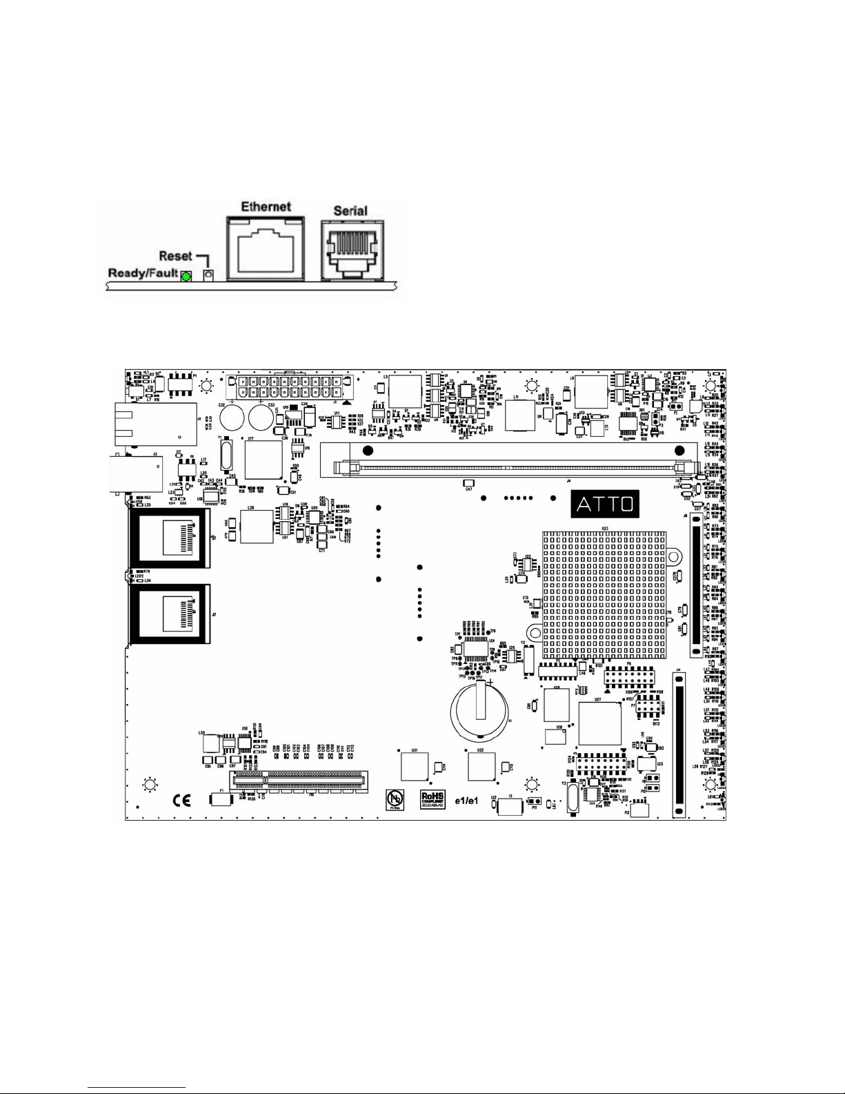
Management ports
Management is provided using either the 10/100/1000
Megabits per second (Mb/sec.) base T Ethernet port
accessible from the RJ-45 connector or the RS-232
management port with a back panel accessible RJ-11
interface.
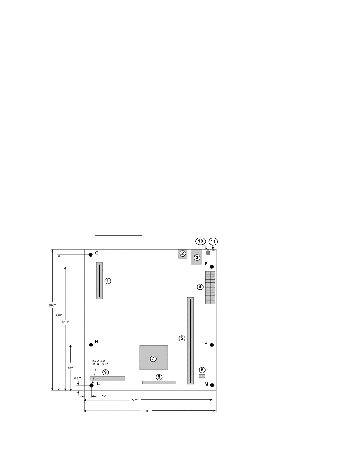
Exhibit 1.1-1 FastStream SC main board layout.
Manual reset switch
A manual reset switch reboots the storage controller.
To reset the FastStream, depress the reset button for
no more than three seconds.
To restore factory defaults, press the reset button for
more than four seconds until the green Ready LED
blinks.
LED
A bicolor LED on the back panel shows unit status:
when green, the unit is in the Ready condition and is
fully operational; if it is lit yellow, a fault has been
detected and you should begin troubleshooting
procedures.
3
ATTO Technology Inc. FastStream SC RAID Controller Installation and Operation Manual
Page 9
1.2 ATTO Celerity FC42-ES Host Adapter
The ATTO FastStream SC 5500E uses the Celerity FC-42ES PCI Express Interconnect and 4-Gigabit Fibre
Channel to provide performance of up to 650 MB/sec.
The Celerity FC-42ES is a dual-channel host adapter
supports high-definition video, rich content databases
and other high bandwidth environments.
The FC-42ES uses PCI Express, a serial, high-speed
connection that supports aggregate throughput up to 4
GB/sec. (x8 PCIe) full-duplex.
Hardware specifications
• 2 independent Fibre Channel ports
• 4-Gigabit data transfer rates per channel
• Supports all FC topologies: direct fabric,
arbitrated loop and point-to-point
• ANSI Fibre Channel: FC-PH, FC-AL, FC-AL2,
FC-FCP, FC-PLDA, FC-FLA
• Flash ROM for easy field upgrades
• FC Class 3 support
• Local management and diagnostics
• Buffer credits: 8 @ 512 Bytes; 8 @ 2 Kilobytes
Advanced FC capabilities
• Supports SNIA HBA API
• On-demand automatic negotiation among 4-Gb,
2-Gb and 1-Gb Fibre Channel
• Supports Windows
• Supports exclusive ATTO Advanced Data
Streaming (ADS) Technology
FDMI and WMI
Host bus specifications
• x4 mechanical and x4 electrical PCI Express
interconnect (RoHS compliant)
• Conforms to PCI Express Base Spec 1.0a
• Conforms to PCI Express CEM Spec 1.0a
• PCI Express to PCI/PCI-X Bridge spec 1.0
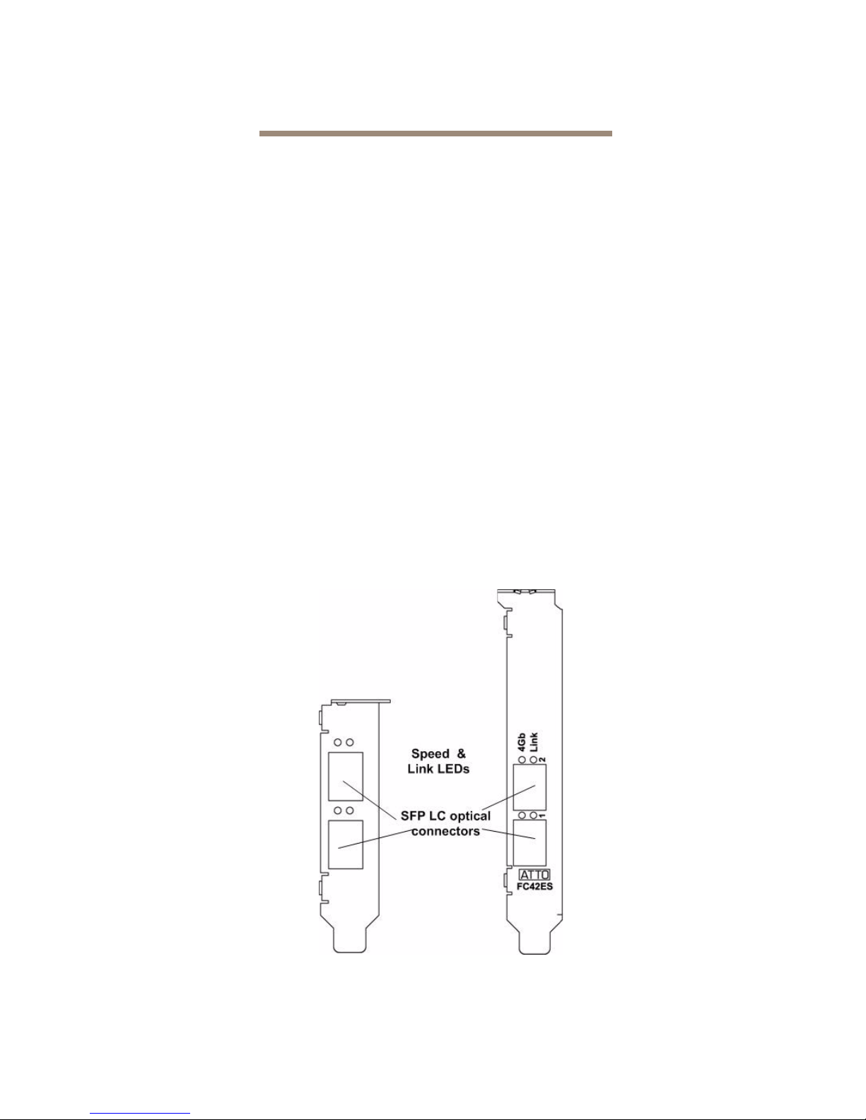
External connectivity
• Easy-to-install full height connection plate
• External LEDs for on-line and speed status for
each channel
• 2 pluggable optical LC SFP transceivers
included
Exhibit 1.2-1 Celerity FC-42ES Adapter bracket detail.
4
Page 10
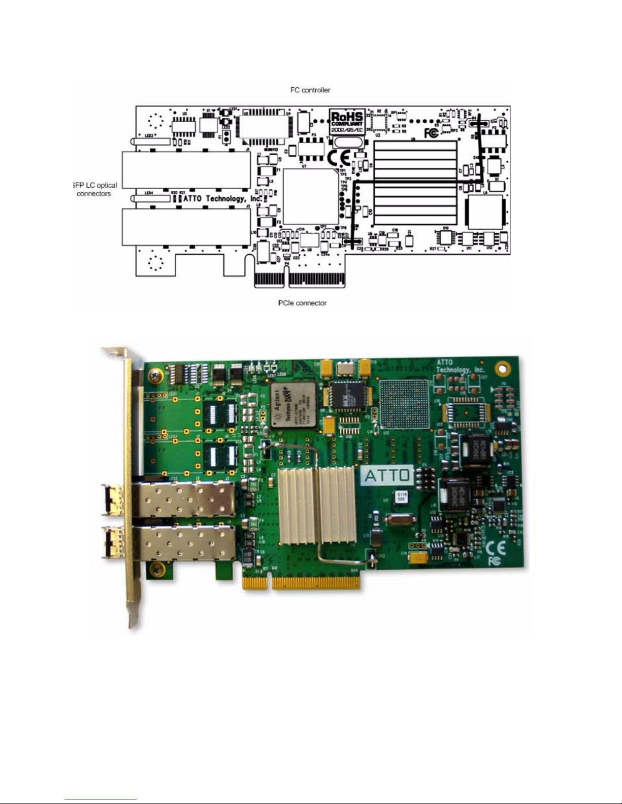
Exhibit 1.2-2 Celerity FC-42ES board layout.
Exhibit 1.2-3 Celerity FC-42ES.
5
ATTO Technology Inc. FastStream SC RAID Controller Installation and Operation Manual
Page 11

1.3 ATTO Celerity FC44-ES Host Adapter
The ATTO FastStream SC 7500E uses the Celerity FC-44ES PCI Express Interconnect and 4-Gigabit Fibre
Channel to provide performance of up to 1200 MB/sec.
The ATTO Celerity FC-44ES supports high-definition
video, rich content databases and other high
bandwidth environments.
The FC-44ES uses PCI Express, a serial, high-speed
connection that supports aggregate throughput up to 4
GB/sec. (x8 PCIe) full-duplex.
Hardware specifications
• 4 independent Fibre Channel ports
• 4-Gigabit data transfer rates per channel
• Flash ROM for easy field upgrades
• FC Class 3 support
• Local management and diagnostics
• Buffer credits: 8 @ 512 Bytes; 8 @ 2 Kilobytes
Advanced FC capabilities
• Supports SNIA HBA API
• On-demand automatic negotiation among 4-Gb,
2-Gb and 1-Gb Fibre Channel
• Supports Windows
• Supports exclusive ATTO Advanced Data
Streaming (ADS™) Technology
Host bus specifications
• x8 mechanical and x8 electrical PCI Express
Interconnect
• Conforms to PCI Express Base Spec 1.0a
• Conforms to PCI Express CEM Spec 1.0a
• PCI Express to PCI/PCI-X Bridge spec 1.0
External connectivity
• Easy-to-install full height connection plate
• External LEDs for on-line and speed status for
each channel
• 4 pluggable optical LC SFP transceivers
included
FDMI and WMI
Exhibit 1.3-1 Celerity FC-44ES Adapter bracket detail.
6
Page 12
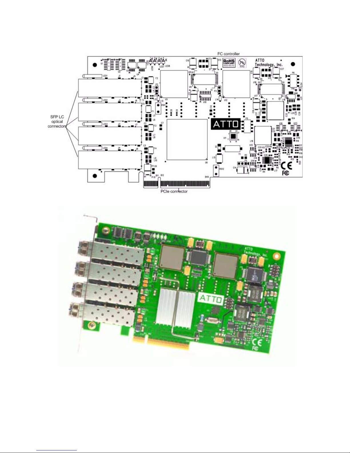
Exhibit 1.3-2 Celerity FC-44ES board layout.
Exhibit 1.3-3 Celerity FC-44ES.
7
ATTO Technology Inc. FastStream SC RAID Controller Installation and Operation Manual
Page 13
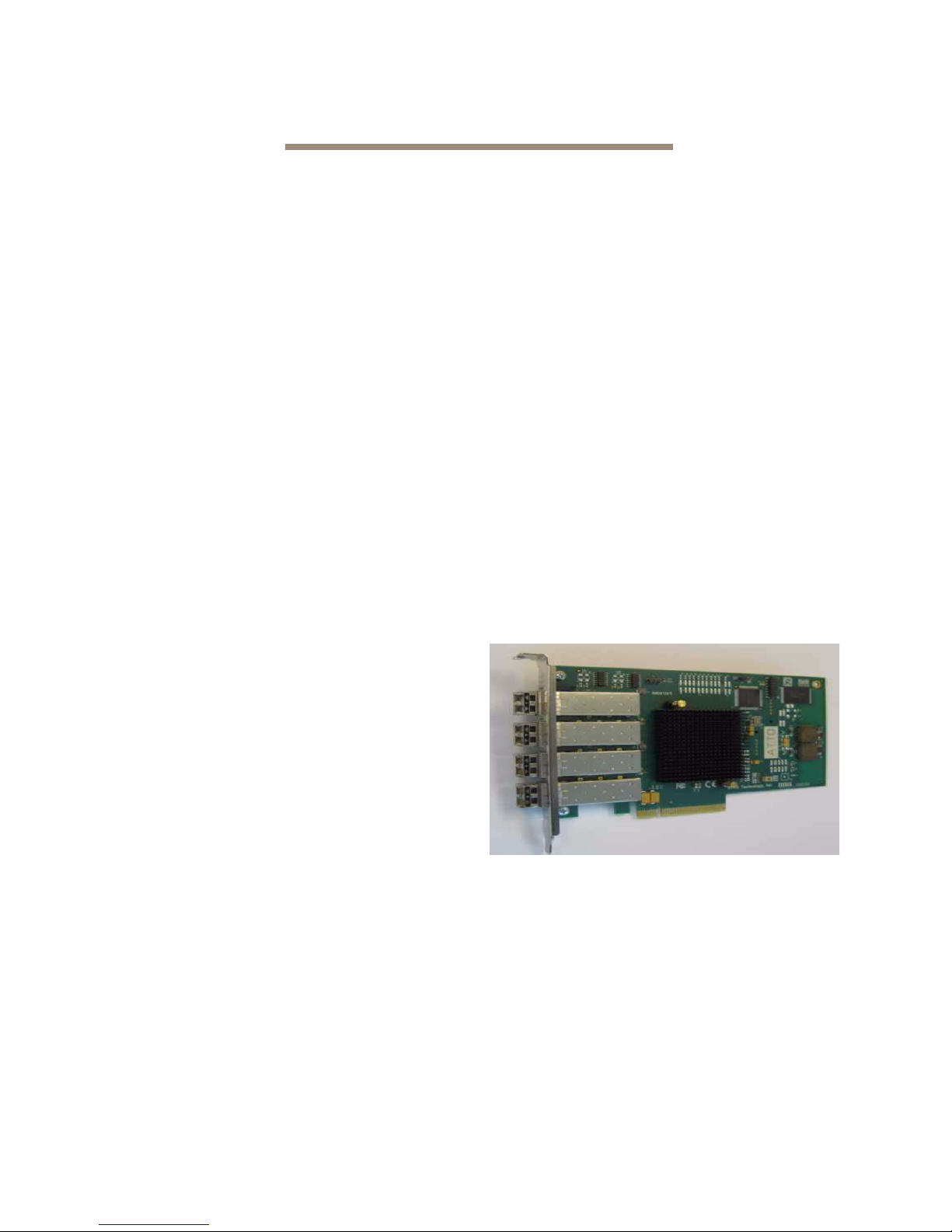
1.4 ATTO Celerity FC84-EN Host Adapter
The ATTO FastStream SC 8500E uses the Celerity FC-84EN PCI Express Interconnect and 8-Gigabit Fibre
Channel to provide performance of up to 1400 MB/sec.
The ATTO Celerity FC-84EN leverages two nextgeneration storage technologies: PCIe 2.0
interconnect and 8-Gigabit Fibre Channel.
The Celerity FC-84EN supports the most demanding
application requirements, including high-definition
video, rich content databases and other highbandwidth environments.
ATTO Celerity host adapters are an integrated family
of advanced storage connectivity solutions that are
designed to provide reliable connectivity, intelligence
and scalability.
Technical specifications
• 4 independent Fibre Channel ports
• 8-Gigabit data transfer rates
• 1600 MB/sec. maximum full-duplex throughput
per channel
• Supports all FC topologies: fabric, arbitrated
loop and point-to-point
• ANSI Fibre Channel: FC-FS, FC-AL, FCP, FCAL2, FC-PLDA, FC-FLA
• Flash ROM for easy field upgrades
• FC Class 3 support
• Local management and diagnostics
• Buffer credits: 41
• ATTO Advanced Data Streaming (ADS™)
Technology
• Conforms to PCI Express Base Spec 2.0
• Conforms to PCI Express CEM Spec 2.0
• PCI Hot Plug spec 1.0
Environmental & physical specifications
• Length: 6.6 inches
• Height: 3.987 inches
• Operating temperature: 0-40 ºC (32-113 ºF)
• Storage temperature: -40 to 70 ºC (-40 to 158 ºF)
• Relative humidity: 10 to 90% non-condensing
• 7.8 W (typical)
• 100 lf/m (minimum) airflow recommended
• RoHS compliant
External connectivity
• Easy to install full height connection bracket
• External LEDs for on-line and speed status for
each channel
• Four pluggable 8-Gb optical LC SFP+ modules
included
Exhibit 1.4-1 Celerity FC-84EN.
Advanced FC capabilities
• Supports SNIA HBA API
• Backward compatible with 4-Gb and 2-Gb Fibre
Channel
• Supports Windows®
FDMI and WMI
Host bus specifications
• x8 mechanical and x8 electrical PCI Express
interconnect
8
Page 14
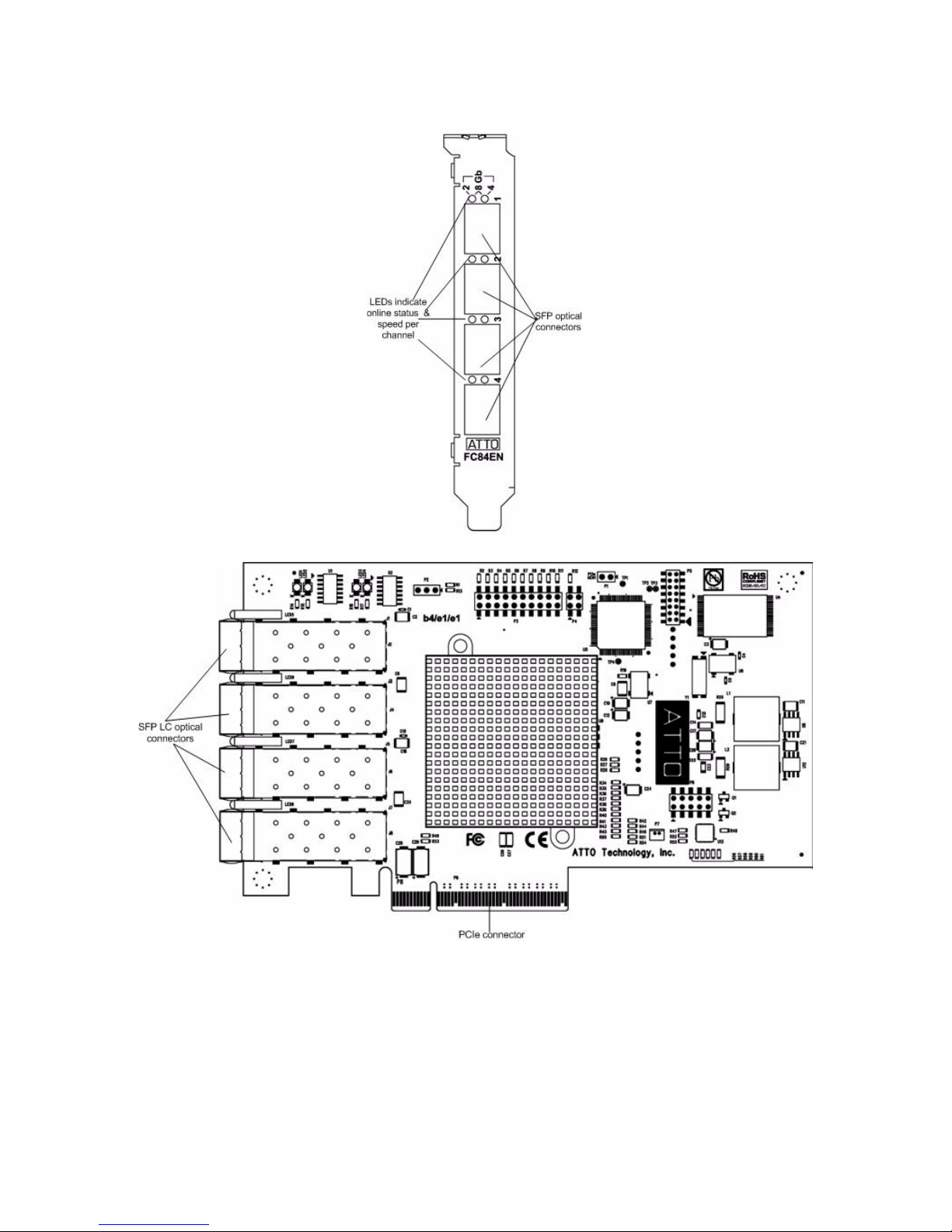
Exhibit 1.4-2 Celerity FC-84En Adapter bracket detail.
Exhibit 1.4-3 Celerity FC-84En board layout.
9
ATTO Technology Inc. FastStream SC RAID Controller Installation and Operation Manual
Page 15

2.0 Install the FastStream
If you have not already completed the instructions on the Quick Start page packed with your
FastStream, use the following instructions to install the FastStream.
Unpacking the packing box; verifying contents
• The FastStream. Note the serial number of your
FastStream unit: ________________________
• 512-megabyte (MB) DDR2-533 ECC DIMM
• Celerity FC-42ES Host Adapter (5500E),
Celerity FC-44ES Host Adapter (7500E) or
Celerity FC-84EN (8500E)
• Cat 5 Ethernet cable, RJ-45, 6 feet
• RS-232 cable, RJ-11 to DB9, 6 feet
Installing the FastStream
See
Exhibit 2.0-1
FastStream mounting holes and components.
1 Ensure you have the following customer-
supplied items available:
• A back panel I/O plate compliant with ATX
specification version 2.1 or greater
• Internal SAS cable
• ATX-compatible storage enclosure
• SAS or SATA drives
2 Ensure the power to the enclosure is off.
3 Install the back panel I/O plate into your
enclosure. (See Exhibit 2.0-2
representation of a typical backplate.)
Note
ATTO Technology does not supply the
backplate because of the variety of enclosures
available. Contact your enclosure
representative for assistance.
4 Install your FastStream into the enclosure.
Note
The FastStream must be supported at all six
mounting points to prevent excessive flexing.
Flex damage caused by excessive force on an
improperly mounted circuit board is not
covered by the product warranty.
1
on page 11 displays the FastStream
mounting holes.
5 Connect the 24-pin ATX power connector from
on page 11 for details on the
on page 12 for a
Exhibit 2.0-
• CD including an Installation and Operation
Manual, firmware, drivers
CAUTIONCAUTION
FastStream SC RAID controllers and
Celerity host adapters contain components
that are sensitive to electrostatic discharge
(ESD). ESD can cause damage to these
components. Please follow standard
methods to avoid ESD.
the enclosure to the FastStream.
6 Install the DIMM module (see Exhibit 2.0-3
page 12).
CAUTIONCAUTION
Use extreme care when installing or
removing the DIMM module to prevent
possible damage.
a. Insert the DIMM module vertically into its
slot on the board, observing the position of
the notch along the bottom of the module to
prevent inserting the DIMM module
incorrectly.
b. Gently press down on the DIMM module
until it snaps into place in the slot.
7 Install the Celerity Host Adapter. See
Exhibit 1.2-1
page 6 for details.
a. Remove the Celerity Host Adapter from its
anti-static bag.
b. Remove the blank plate from slot 7 of your
enclosure.
c. Position the Celerity card directly above the
PCIe slot and push the card straight down.
For easier installation, place one end of the
host adapter into the slot first, then gently
push on each end until the unit is seated.
d. To ensure the card is seated completely,
give it an extra uniform push on each end
simultaneously.
e. Install the panel screw to secure the card.
8 Attach FastStream internal SAS I/O cables.
on page 4 and Exhibit 1.3-1 on
on
10
Page 16
The internal SAS physical interface consists of
the 32-pin SFF-8484 connectors. The internal
cable can be unshielded and should terminate
from the SFF-8484 connector in the enclosure.
a. Plug in the corresponding end of the
internal SAS cable to the FastStream SC
internal SAS connector (port A and/or port
B).
b. Plug in the opposite end of the internal SAS
connector to the corresponding connector
of the enclosure backplane or SAS/SATA
peripheral.
9 Attach a management interface cable.
You may manage the FastStream using either
an RJ-45 Ethernet cable or an RJ-11 serial
cable.The preferred manageme n t too l is the
ExpressNAV graphical user interface accessed
through the Ethernet cable.
RJ-45 Ethernet cable: A board-mounted RJ-45
connector at the back I/O panel connects with a
10/100/1000 baseT category 5 or 6 Ethernet
a. Align the tab on the Ethernet cable with the
tab on the Ethernet port of the FastStream.
b. Insert the cable until it positively mates and
locks into place.
RJ-11 serial cable: A board-mounted RJ-11
cable at the back I/O panel makes connection
with an RS-232 serial port for appliance
management.
a. Align the tab on the provided serial cable
with the tab on the RJ-11 serial port of the
FastStream
b. Insert the cable until it positively mates and
locks into place.
c. Insert the other end of the serial cable into
the DB9 port of the PC being used for
appliance control.
10 Install drives into your enclosure according to
the enclosure and drive manufacturers’
instructions.
11 Put the cover back on the enclosure.
12 Power up the unit.
cable. If using an Ethernet network at 1000
baseT, use a category 6 cable to make the
connection. The FastStream ships with Cat 5
cable.
Exhibit 2.0-1 FastStream SC RAID controller co mponents, dimensions and mounting holes. For pinout
information, refer to
Reference Charts on page xxiv of the Appendix.
11
ATTO Technology Inc. FastStream SC RAID Controller Installation and Operation Manual
1 PCI-e connector (J10)
2 RJ11 serial port connector (J3)
3 RJ-45 Ethernet connector (J2)
4 ATX 24-pin power connector (J1)
5 Vertical SDRAM DIMM connector
6 ATX power switch header (P3)
7 Intel 81348 storage processor
8 Internal SAS P ort A con n e c to r (J 9 )
9 Internal SAS P ort B con n e c to r
(J11)
10 Momentary reset pushbutton
11 Back panel ready/fault LED
Mounting holes are labeled C, F, H,
J, L and M.
Page 17
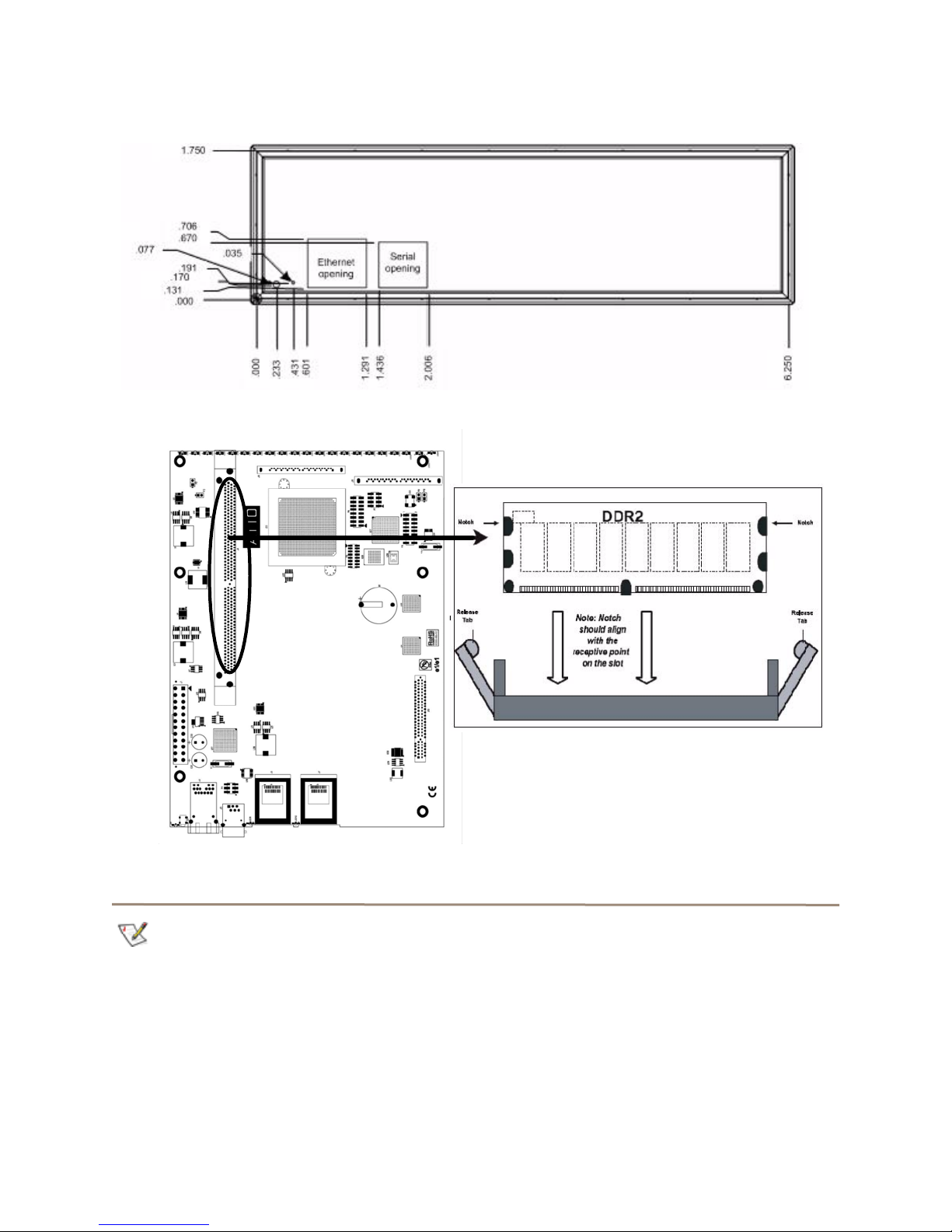
Exhibit 2.0-2 Back panel I/O plate.
Exhibit 2.0-3 Insert the DIMM module vertically into its slot on the board.
Discovering the IP address
Note
The FastStream is initially configured with
DHCP enabled. It is best if you have access to
a DHCP server.
1 Work from the computer attached to the
FastStream Ethernet port. From the CD
supplied with your FastStream, run the
QuickNav Utility QuickNAV-windows.exe for
Windows or QuickNAV-Mac for Mac OS X.
2 Locate the FastStream with the serial number
recorded earlier.
3 Highlight the serial number.
4 Click Next.
If a DHCP server is available on your network,
an address is assigned automatically by the
server. Note the assigned address:
_____________________________________
12
Page 18

If you do not have a DHCP server, get an IP
address and subnet mask from your network
administrator, type it into the area provided, and
click on Next.
5 Click on Launch Browser.
Setting up Internet Explorer
Your browser points to the ATTO ExpressNAV
splash screen. If you use Internet Explorer as a
browser, continue on to the optional Setting up
Internet Explorer below. If not, continue on to
Beginning initial configuration
.
1 Open your browser.
2Select Internet Options.
3 In the Internet Options screen, select the
Security tab.
4 Click on the Trusted Sites icon.
5 Click on the Sites button.
6 In the text box Add this Web site to the zone,
add the IP address of the controller. You may
Beginning initial configuration
1 The ExpressNAV interface welcome screen
appears. Click on Enter Here.
2 Type in the user name and password.
Note
The default values are user name
password
insensitive and the password is case sensitive.
Password
. The user name is case
root
and
use wild cards.
7 Click on Add.
8 Uncheck the Require server verification
check box.
9 Click OK.
10 At the bottom of the Internet Options box, click
on OK and close the box.
It is best practice to change the default user
name and password. Refer to
current user name, password
3The Initial Setup page appears. Continue to
Ensure Drive Integrity
on page 14.
Changing
on page 21.
13
ATTO Technology Inc. FastStream SC RAID Controller Installation and Operation Manual
Page 19
3.0 Ensure Drive Integrity
The A TTO FastS tream “Initialize and V erify drive” feature discovers and remaps bad sectors on drives, providing
reliable media for your RAID groups.
Before creating any RAID group you should Initialize
and Verify the drives you want in the RAID group to
ensure drive integrity. When selected, the FastS tream
writes a pattern to the entire drive, verifying the drive’s
readiness and reliability.
CAUTIONCAUTION
Selecting Drive Initialization causes all
previous storage data on the drive to be
erased. Make sure all of your information is
backed up before initializing drives.
During initialization and verification, the FastStream
collects performance measurements. Performance
data is available once initialization begins. You may
view it from the
page accessible from the
performance data is lost when the controller is
powered off.
Drive Performance and Health
Diagnostics
menu. This
If you do not want to initialize or verify drives now,
continue on to
on page 15.
Check drive integrity after you have created RAID
groups on drives which you wish to add to your
FastStream configuration. This can be accomplished
by using the
only scan of drives.
The
Read-Only Drive Test
destructive scan over the entire surface of each drive
to identify bad areas of disk drives and determine read
performance. It may be run while data is passing
through the FastStream.
Running this test may negatively impact performance.
Once the
system operation returns to normal.
Configure Storage into RAID Groups
Initialize and Ve rify
Read-Only Drive Test
procedure or a read-
performs a non-
has completed,
Before creating RAID groups
1 If you are not already in the ExpressNAV
Storage Manager, type the IP address of your
controller in a standard browser. On the splash
screen, click Enter Here. In the box provided,
type in your user name and password, and click
OK.
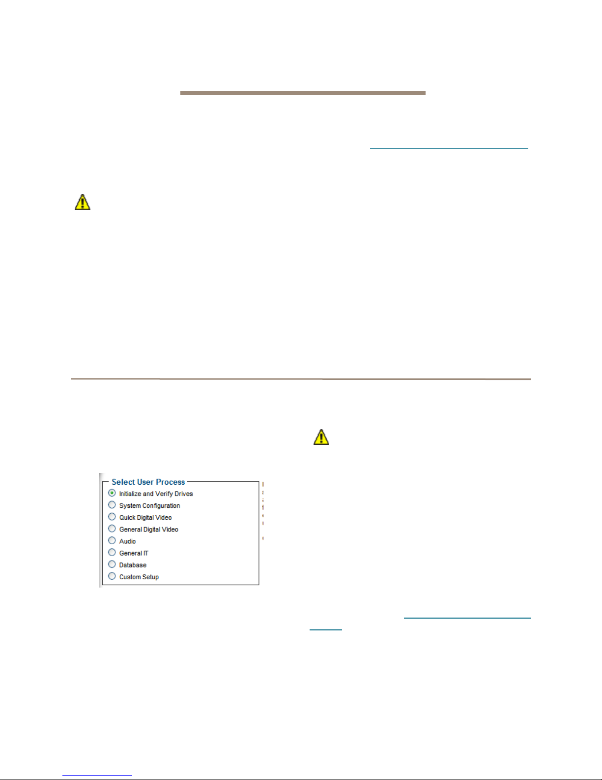
2Select Initialize and Verify Drives.
3 Click Next.
4Select Initialize and Verify Drives.
All eligible drives are highlighted in green; the
system only initializes highlighted drives.
5 Click Commit.
CAUTIONCAUTION
Do not restart the FastStream or
disconnect or power cycle drives during
Drive Initialization and Verification or you
must start the verification process from the
beginning.
6 A warning box appears. In the warning box,
verify that you want to complete the
configuration by clicking on Yes. Clicking on No
ends the procedure without making a change.
7 When the process is complete, the Drive
Performance and Health page appears.
The drive(s) selected are now initialized and verified.
All data on the highlighted drives has been erased and
you may continue with
Groups
on page 15.
Configure Storage into RAID
14
Page 20
After creating RAID groups
1If you are not already in the
ExpressNAV Storage Manager,
type the IP address of your
controller in a standard browser.
On the splash screen, click
Enter Here. In the box provided,
type in your user name and
password, and click OK.
2 Click on the Diagnostics button on the left
hand side of the ExpressNAV Storage
Manager.
3 Choose Initialize and Verify Drives to test
newly added drives that are not part of a RAID
group. Choose Read-Only Drive Test to nondestructively test any drives.
4 Click Next.
5 If no drives appear in the information box, click
on the System Scan button.
If drives are available, click on the drives you
wish to verify, initialize or test; the drives are
highlighted.
6 Click Commit.
CAUTIONCAUTION
Do not restart the FastStream or
disconnect or power cycle drives during
Drive Initialization and Verification or you
must start the verification process from the
beginning.
7 A warning box appears. In the warning box,
verify that you want to complete the
configuration by clicking on Yes. Clicking on No
ends the procedure without making a change.
8The Drive Performance and Health page
appears showing what tests are running and
their results. You may select other tests to run
or continue on to other tasks.
15
AT TO Technology Inc. FastStream SC Installation and Operation Manual
Page 21
4.0 Configure Storage into RAID Groups
The ATTO FastStream allows configuration of storage into DVRAID, JBOD, RAID Level 0, 1, 1+0, 4, 5 or 6 with
the ability to create multiple partitions.
RAID is a storage configuration which uses multiple
drives to increase capacity, performance, and/or
reliability . The FastStream can automatically set up an
application-ready RAID configuration. Also, you may
custom design a RAID configuration, or combine a
custom and an automatic configuration.
The FastStream uses all available drives when you
select
Quick Digital Video, General Digital Video,
Audio, General IT,
include those which are on-line and not currently
configured for RAID or Hot Sp ares.
If you wish to have more than one type of RAID group
in your system, you have several options:
• Set up a customized RAID group (refer to
Creating a custom setup
return to the main menu and select a particular
application to use the remainder of your
attached storage.
• Attach only the storage you want using an
automated setup (refer to Selecting an
application ), then attach more storage and use
either the custom or specific user processes
outlined in this chapter.
• Set up storage now using any of the processes
in this chapter, then modify or add to storage
or
Database
. Available drives
on page 19), then
using the procedures listed in Modify Storage
page 34.
CAUTIONCAUTION
Before creating any RAID group you
should initialize and verify the drives you
want in the RAID group. Refer to
Drive Integrity
RAID improves data accessibility and
reliability during normal operations,
however, you still need a good backup
strategy for long-term protection of data.
When you have created RAID groups, you may use,
monitor and modify the storage as needed. Refer to
Monitor Storage, Configurations
System Values
Configurations
page 34.
on page 21
on page 39, and
on page 14.
on page 23,
Manage ATTO Devices,
Modify Storage
on
Ensure
Modify
on
Features you may choose
Depending on the application you choose, the number
of drives you choose and several other factors, you
may have other choices to customize your FastStream
to your particular needs.
Some features are customized by you only if you use
the custom setup. Refer to
on page 19.
Auto-Rebuild
When
Auto-Rebuild
group member becomes faulted, the controller initiates
a rebuild using an available unallocated drive. If no
drives are available, the rebuild is initiated only after
you replace the faulted drive and initiate a system
Creating a custom setup
is enabled and an existing RAID
scan to discover the drive. Hot Sp ares will be used
first, regardless of the Auto-Rebuild setting.
V arious outcomes are available when Auto-Rebuild is
enabled.
• If an existing RAID group member becomes
faulted or unavailable, such as when a drive is
pulled out from an array, the controller initiates a
rebuild using an available unallocated drive.
• If the controller boots up with drives missing or
faulted, the FastStream tries to switch them out
automatically.
• If no unallocated drive is available, you must
replace the faulted drive and a rebuild will begin.
Hot Spares are not required, allowing the
maximum number of drives for data storage.
16
Page 22

However, if you require maximum fault
tolerance, it is best practice to have a Hot Spare
available to supply the unallocated drive for
immediate use. Refer to FastStream process:
adding or removing Hot Spares on page 37.
Fault Tolerance
Choose either
Spare drives) or
adds Hot Spa res to the system) when creating parity
RAID Groups. Refer to
or removing Hot Spares
Standard Fault Tolerance
Maximum Fault Tolerance
FastStream process: adding
on page 37 for details.
(no Hot
(which
Selecting an application
Initialization
If you have not already initialized your drives as
outlined in
may choose to use the
new drives to erase and verify drive media and correct
some soft drive errors. The RAID Group is unavailable
until the operation completes.
Choose Express Initialization
background initialization if you have already
completed a full initialize and verify operation. The
RAID Group being initialized is available for use during
express initialization.
Ensure Drive Integrity
Advanced Initialization
on page 14, you
for
to perform a quick
After initializing drives or setting up new storage,
select an application from the
Manage
drives and creates the appropriate setup using those
drives.
The most flexible choice is to use
you must understand your needs and your system well
to use this option.
Refer to
Appendix for more information about RAID.
page. The FastStream finds all available
Design RAID Groups
Initial Setup
Custom Setup
on page xvii of the
or via the
, but
Preliminary steps
1 If you are not already in the ExpressNAV
Storage Manager, type the IP address of your
controller in a standard browser. On the splash
screen, click Enter Here. In the box provided,
type in your user name and password, and click
OK.
2 If you have not performed the steps detailed in
Ensure Drive Integrity
other RAID groups, the Initial Setup Menu
appears.
If you have initialized your storage or created
other RAID configurations,
a. From the selections at the left, select
Manage.
b. Click on the RAID Groups arrow.
c. Click on Create RAID Group.
d. Click on Next.
3 Select one of the following and continue using
the directions in each specific section:
• Quick Digital Video: provides parity RAID
protection (DVRAID) and optimized
performance for digital video (sequential
access) configurations.
on page 14 or created
Note
DVRAID is only available using the
Digital Video
• General Digital Video: provides parity RAID
protection for digital applications for
configurations using three or more drives.
• Audio: Audio track streaming technology
provides parity RAID protection while managing
latency to allow high-speed availability to
support up to 192 tracks of 16-bit audio or 96
tracks of 24-bit audio in a single editing session.
You must have only 4, 6, 8 or 12 drives available
in the system.
• General IT: provides parity RAID protection
optimized for random access applications using
three or more drives.
• Database: provides parity RAID protection for
database applications (small transfer, random
access) for configurations using more than three
drives.
setup wizard.
Quick
Quick Digital Video
1 After choosing Quick Digital Video, the Setup
Wizard page appears.
Select your operating system.
2 If you chose Windows, click Yes and the
system restarts. After the restart completes,
continue to Step 3
If you chose Mac, continue on to Step 3
3 If all your drives do not appear in the Find
Drives box, click on System Scan.
For the FastStream 5500E, 7500E and 8500E,
this setup requires exactly 6, 12 or 24 drives
appear as available on the screen after the
scan.
.
.
17
AT TO Technology Inc. FastStream SC Installation and Operation Manual
Page 23

Physically add or disconnect drives as needed
and rescan.
4 Click Next.
5 Choose an Initialization method (refer to
Initialization
6 Choose an Auto-Rebuild option (refer to Auto-
Rebuild on page 16).
7 Select a Fault Tolerance (refer to Fault
Tolerance on page 17).
8 Click Commit.
9 A warning box appears.
If you want to continue click Yes. The
configuration completes and the Health and
Status Monitor page appears.
If you wish to start over, click No.The Setup
Wizard page appears.
on page 17).
Audio
1 After choosing Audio, the Audio Setup
Wizard page appears.
Choose to use the same or a different node
name for each host Fibre Channel port.
• If you know you want all drives to be available
or unavailable to all Fibre Channel ports,
select Yes or No. If you do not know, select
Not Sure.
• If you select Not Sure, you are asked a
series of questions to determine the correct
configuration for your needs and setup.
• Several definitions are listed in a grey box at
the bottom of the Audio Setup Wizard
screen which may help you determine
answers to the setup questions.
2 Click on Next.
Note
Depending on your choice and your current
system, the controller may need to restart.
3 If all your drives do not appear in the Find
Drives box, click on System Scan.
This setup requires 4, 6, 8 or 12 drives.
Add or disconnect drives as needed to ensure
you have 4, 6, 8 or 12 drives appearing on the
screen after the scan.
4 Click Next.
5 Choose an Initialization method (refer to
Initialization
6 Choose an Auto-Rebuild option (refer to Auto-
Rebuild on page 16).
7 Select the number of users for this controller.
8 Depending on the number of users and the
number of drives you have in your system, you
may be asked choose a Fault Tolerance (refer
to Fault Tolerance
9 Click Commit.
10 A warning box appears.
If you want to continue click Yes. The
configuration completes and the Health and
Status Monitor page appears.
If you wish to start over, click No. The Setup
Wizard page appears.
on page 17).
on page 17).
General Digital Video, General IT or
Database
1 After choosing General Digital Video, General
IT or Database, the Setup Wizard page
appears.Choose an Initialization method
(refer to Initialization
2 Choose an Auto-Rebuild option (refer to Auto-
Rebuild on page 16).
3 If all your drives do not appear in the Find
Drives box, click on System Scan.
4 Click on Commit.
5 A warning box appears.
If you want to continue click Yes. The
configuration completes and the Health and
Status Monitor page appears.
If you wish to start over, click No. The Setup
Wizard page appears.
on page 17).
18
Page 24

Creating a custom setup
If the application setups do not suit your needs, you
may use
1 After choosing Custom Setup button, the
2 Decide if all drives are to be available to both
3 Select a RAID level. Refer to Design RAID
4 Type a unique name for your RAID gro up in the
5 Click Next.
6 If an SES enclosure is found and it has drives
7 Click on the System Scan button to discover
8 When the scanned drives box is populated,
9 Click Next.
10 The Partition wizard appears.
Custom Setup
RAID Setup Wizard page appears. Click on
Next.
ports.
• If you select Yes, the same node name is
assigned to both ports.
• If you select No, different node names are
assigned to each FC port.
• The choice you make establishes the access
for all RAID groups attached to this
FastStream.
Groups on page xvii of the Appendix.
If you selected RAID 1 with Multiple Mirrors,
type in the number of mirrors (copies) of the
original data you want to maintain in the box
provided.
box provided on the page under the Step 3
heading.
associated with it, choose a method for
selecting drives from the following:
a. Use all drives in an enclosure for your RAID
Group
b. Use all drives in an enclosure for your RAID
Group plus one for a Dedicated Hot Spare
c. Select your own drives
the drives available for RAID configuration.
click on the boxes representing the drives for
the RAID group named in Step 4.
to configure the FastStream.
• A RAID group may have several Terabytes of
total data capacity because of the size of the
included drives. Partitions allow you to break
up large RAID groups into smaller, more
manageable groups.
• Most host systems can address only 2 TB per
LUN. Partitioning increases storage
efficiency by providing more LUNs without
using lower capacity RAID groups.
• Partitioning allows the creation of multiple
logical volumes.
Note
If you don't want to use partitions, click on the
All Unallocated
a. Enter the desired partition size from the
available RAID group capability.
b. Click Create.
c. Repeat entering the partition size and
clicking on Create as often as you need to
partition the remaining capacity. Whenever
you have completed designating partitions,
click on the All Unallocated button to put
all the remaining capacity into one partition.
11 Click Next. The storage capacity is allocated.
12 RAID partitions are mapped onto the Fibre
Channel network as FC LUNs. Select the
method you wish to use to map the partitions.
• If you select Auto, all mapping for all RAID
groups attached to this FastStream is
changed, destroying any previous mapping.
• If you do not wish to change the mapping of
your other RAID groups, select Manual.
Manual mapping allows you to make LUN
assignments for each RAID partition in the
selected RAID group.
a. From the RAID Configuration page
presented, under Select the mapping
method, click the Manual radio button.
b. Click on any partition to map that partition to
a Port and LUN.
13 Choose an Initialization method (refer to
Initialization
14 Choose the Interleave by clicking on the drop
down box.
CAUTIONCAUTION
The default value is usually best. Changing
the default interleave size may degrade
performance.
on page 17).
button.
19
AT TO Technology Inc. FastStream SC Installation and Operation Manual
Page 25

15 Select a Sector Size.The RAID group sector
size must be evenly divisible by the sector size
of any member disk.
• 512 bytes is the default size for most
operating systems.
• For Windows XP (32-bit support) select 4 KB
sectors to enable large volume support
(greater than 2 TB).
16 Select a SpeedRead feature. SpeedRead
looks ahead during reads and stores the data in
cache memory. The optimum setting depends
on your actual I/O and storage. You may adjust
this setting later.
• Enabling SpeedRead may boost
performance when you are running video
playback and other applications which
access data sequentially.
• Disabling SpeedRead is a better choice for
audio applications.
• SpeedRead Auto is usually the best choice
for database applications.
17 Choose a Prefetch option--the number of extra
stripes that are read when the SpeedRead
setting is set to enabled or auto.
18 Choose an Auto-Rebuild feature if it is
available for your RAID configuration (refer to
Auto-Rebuild
19 Choose a Rebuild Priority level. Rebuild
Priority allows you to determine whether rebuild
or I/O transactions take precedence during
rebuild operations. If you choose low priority,
for example, rebuilds take longer but the rebuild
has minimal impact on performance.
20 Click on Next.
21 A chart showing the setup you have selected
appears. If everything is the way you want it,
click on Commit to save your configuration.
22 For RAID types that rebuild, a warning box tells
you that all data on the attached disks is to be
destroyed and the rebuild process.
In the warning box, verify that you want to
complete the configuration by clicking on Yes.
Clicking on No ends the procedure without
making a change.
23 The FastStream configures the storage (the
process may take several hours). Upon clicking
Yes, the Health and Status Monitor page
appears.
on page 16).
20
Page 26

5.0 Modify System Values
Default values are appropriate for most configurations, but may be modified for your needs using ATTO
ExpressNAV Storage Manager.
It is best practice to change the default user name and
password to a user name and password important to
you. Other configurations may also be changed,
Changing current user name, password
however, use extreme caution when changing default
values.
It is best practice to change the user name and
password on all Telnet, FTP and ATTO ExpressNAV
Storage Manager sessions. Refer to the CLI
commands Username and Password in
1 Open a Command Line Interface session either
using Telnet or the serial port as shown in
Interface Options
2Type set UserName [name].
3 Press Enter.
4Type set Password.
on page 41.
Appendix A
5 Press Enter.
6 Follow the instructions on the screen to confirm
your old and new password.
.
Note
The user name is case insensitive and
password is case sensitive.
The user name and password for all Telnet, FTP
and ATTO ExpressNAV Storage Manager
sessions is changed.
Creating a read-only user name, password
You may wish to set up a read-only user name and
password to prevent changes to storage and
FastStream settings. Refer to the CLI commands
ReadOnlyPassword and ReadOnlyUsername in
Appendix A
1 Open a Command Line Interface session either
using Telnet or the serial port as shown in
Interface Options
.
on page 41.
2Type set ReadOnlyUsername [name].
3 Press Enter.
4Type set ReadOnlyPassword.
5 Press Enter.
6 Follow the instructions on the screen to confirm
the read-only password.
The read-only user name and read-only password for
all user interface sessions is changed.
Changing system variables
Y ou may change several system configurations to suit
your needs.
1 If you are not already in the ExpressNAV
Storage Manager, type the IP address of your
controller in a standard browser, click Enter
Here on the splash screen, then type in your
user name and password in the box provided.
Click OK.
2 Click on the Manage menu item on the left
hand side of the page.
21
AT TO Technology Inc. FastStream SC Installation and Operation Manual
3 Click on the FastStream arrow.
4 Click on the System Configuration radio
button.
5 Click on Next.
6 Make any changes.
Page 27

• Controller name: the controller name is a
unique 8-character identifier which is
displayed at the top of each screen. You may
find this useful if you are managing multiple
ATTO devices from a single workstation.
• Time and date: use a remote time server to
set the time and time zone, or manually set
the time and date. Refer to Date, Time,
TimeZone in Appendix A
.
• Fibre Channel: change the data rate or the
connection mode for each FC port. Refer to
FCDataRate and FCConnMode in
Appendix A
.
• Assign a hard address: refer to FCHard and
FCHardAddress in Appendix A
.
• Establish Access through FC Ports:
change whether all drives are to be available
to both ports, creating one node name for
both ports, or if different node names sh ould
be created for each port.
• Ethernet management port: change
whether or not you use DHCP for an IP
address, subnet mask and gateway, or
manually change these parameters and set a
DNS server address. Refer to IPDHCP in
Appendix A
.
• When you have completed your changes,
click on Commit.
22
Page 28

6.0 Monitor Storage, Configurations
You may determine the performance of drives attached to the FastStream using various displays and tests in
ExpressNAV Storage Manager.
The following instructions assume you have already
set up at least one RAID group.
The ATTO FastStream collects various metrics to
measure performance for physical drives attached to
the FastStream during normal system operation and
drive initialization and verification.
Health and Status Monitor page
Note
New performance data is updated every 60
seconds which impacts performance slightly,
even if you minimize the browser window . Exit
the ExpressNAV S torage Manager completely
whenever you need maximum performance.
The
Health and Status Monitor
page you see when you open the ExpressNAV
Storage Manager afte r completing the configuration of
at least one RAID group. You may return to it at any
time by clicking on the
side of the screen.
1 If you are not already in the ExpressNAV
Storage Manager, type the IP address of your
controller in a standard browser. On the splash
Monitor
page is the first
button on the left hand
screen, click Enter Here. In the box provided,
type in your user name and password, and click
OK.
2The Health and Status Monitor page a ppears.
If you click Details, added information about
each parameter appears on the Configuration
Display page (refer to Configuration Display
page on page 24).
23
AT TO Technology Inc. FastStream SC Installation and Operation Manual
Page 29

Configuration Display page
Clicking on
Monitor
various aspects of the FastS tream and attached
storage. Click on the arrow next to the group you wish
to view.
• RAID groups: RAID group names, RAID status,
available Hot Spares, number of faulted drives,
RAID Level, number of partitions, Interleave and
total capacity of each RAID group
Details
page gives you added information about
from the
Health and Status
• Partitions: RAID group name, partition ID,
capacity and block size
• Drives: Drive configuration by port, including
drive size and status
• Interfaces: Ethernet management port link
status and Fibre Channel port link, speed,
connection mode, Node Name and Port Name
SCSI Enclosure Services (SES)
Drive enclosures may have a SCSI Enclosure
Processor which indicates enclosure health status,
drive identification and drive fault identification.
The ATTO FastStream recognizes drive enclosures
that provide SCSI Enclosure Services (SES).
Use SES to identify individual drives, all the drives in
the same enclosure, all the drives in a single RAID
group, or faulted drives.
Clicking on Details from the
Monitor
Enclosure Services (SES)
page for enclosure status gives you the
Health and Status
SCSI
on page 29.
24
Page 30

6.1 Remote System Monitoring
You may set up the FastStream to send notifications using Email when certain events occur.
You may set up the FastStream to send notifications
when certain events occur using
page of the ExpressNAV Storage Manager.
You designate the person receiving notification of
conditions and the level of severity which prompt
notification using Email notification.
Error Notifcation
Types of errors
• Device/drive errors such as medium error,
aborted command and hard error
• Device/drive transitions from online to offline
• Critical and warning temperature conditions
• Critical and warning voltage conditions
• Power recycle/power failure conditions
• Enclosure issues, when SES is Available
Email notification
Warning messages
• device down
• medium error
• abort command
Message severity levels
• Critical: critical event Emails
• Warning: warnings and critical event Emails are
sent
• Informational: information which you may want
to know but which probably does not require
action: only information messages are sent
• All: warnings, critical events and informational
messages
• None: no Emails are sent
Phone home Email notification allows the FastStream
to send an Email message to you, a network
administrator or other users when certain events occur
with the FastStream.
Serious error messages are sent immediately, while
messages for less serious errors are sent every 15
minutes.
You may send Emails to up to five Email addresses
and designate which conditions prompt each Email
notification.
For example, a recipient with a critical severity level
only receives critical messages and not warning or
informational messages.
When an event occurs that warrants Email notification,
the FastStream sends the message; it cannot respond
to a rejection by a server for an invalid address.
Ensure all Email addresses typed in are valid.
Each Email is time stamped when it is sent as part of
the SMTP header information.
1 If you are not already in the ExpressNAV
Storage Manager, type the IP address of your
controller in a standard browser. On the splash
screen, click Enter Here. In the box provided,
type in your user name and password, and click
OK.
2The Health and Status Monitor page appears.
On the menu at the left hand side of the page,
choose Manage.
3The Manage Menu page appears. Click on the
FastStream arrow.
4 Click the Set up Error Notification button.
5 Click Next.
6 Click on the Enabled button for Notification
Configuration.
7 Type in the sender address or use the default.
(Emails show this name in the From field).
8 Type or use the default SMTP Server (the
Email server) IP address or the name of the
SMTP server and, if required, the user name
and password used to log into the server.
9 Type in up to five Email addresses.
10 Choose All, Critical, Warning, Informational
or None for each Email address.
11 When all information is typed in, click Commit.
12 A warning box appears. In the warning box,
verify that you want to complete the notification
procedure including a restart of the FastStream
25
AT TO Technology Inc. FastStream SC Installation and Operation Manual
Page 31

by clicking on Yes. Clicking on No ends the
procedure without making a change.
Exhibit 6.1-1 The Error Notification page.
13 Your settings are displayed. You may change
or disable Email notification at any time from
the Error Notification page.
26
Page 32

6.2 Drive Diagnostics
You may determine the performance of drives attached to the FastStream using various displays and tests in
ExpressNAV Storage Manager.
The following instructions assume you have already
set up at least one RAID group.
The ATTO FastStream collects various metrics to
measure performance for physical drives attached to
the FastStream during normal system operation and
drive initialization and verification.
New performance data is updated every 60 seconds
which impacts performance slightly, even if you
minimize the browser window. Exit the ExpressNAV
Storage Manager completely whenever you need
maximum performance.
Note
Initialize and Verify Drives is Described in
Section 3.0,
14.
Ensure Drive Integrity
on page
Preliminary steps
1 If you are not already in the ExpressNAV
Storage Manager, type the IP address of your
controller in a standard browser. On the splash
screen, click Enter Here. In the box provided,
type in your user name and password, and click
OK.
2The Health and Status Monitor page a ppears.
Click the Diagnostics button on the left hand
menu.
3 Select the operation you wish to perform from
the next menu presented.
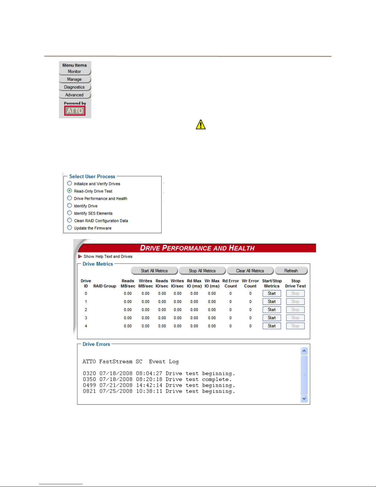
Read-only Drive Test
The
Read-Only Drive Test
destructive scan over the entire surface of each drive
to identify bad areas of the disk drives and determine
read performance. It may be run while data is passing
through the FastStream.
Running this test may negatively impact performance.
Once the
system operation returns to normal.
To fix errors on disks, use the
Drives
Integrity
1 Follow the instructions in Preliminary steps
2 Click the Read-Only Drive Test button.
3 Click Next.
Read-Only Drive Test
process as described in
on page 14.
above.
performs a non-
has completed,
Initialize and Verify
Ensure Drive
4 If no drives appear in the information box, click
on the System Scan button.
If drives are available, click on the drives you
wish to test; the drives are highlighted.
5 Click Commit.
6 A warning box appears. In the warning box,
verify that you want to complete the
configuration by clicking on Yes. Clicking on No
ends the procedure without making a change.
If you chose to do a
Drive Performance and Health page appears
showing what tests are running and their
results. You may select other tests to run or
continue on to other tasks.
Read-Only Drive T est
, the
27
AT TO Technology Inc. FastStream SC Installation and Operation Manual
Page 33

Drive performance and health
Another way to determine your drives’ status is to
follow the instructions in Preliminary steps
27, and click on the
menu item.
1 Follow the instructions in Preliminary steps
above.
2 Click on the Drive Performance and Health
menu item.
3The Drive Performance and Health page
appears.
• Click on Show Help Text and Drives for an
alternative view of the test progress.
• During the tests the Time Remaining box
tells you how much time remains until the
verification process is complete. The
Drive Performance and Health
on page
representation of each drive in the Drives
box shows the percentage of verification
completed.
• Drive performance is displayed under the
Drive Metrics section.
• Drive errors are displayed in the Drive
Errors section of the page.
4 When the test is complete, click on each drive
to see its information highlighted in the Drive
Metrics window.
If you close the browser or navigate away from this
page, you may re-access these results by clicking the
Diagnostics
Performance and Health
available until the FastStream is restarted.
button and choosing the
Identifying a drive attached to the FastStream
Y ou may want to physically identify a drive attached to
the FastStream. This method will work even if SES is
unavailable.
CAUTIONCAUTION
Executing this command adversely
impacts performance and throughput for
the time that the LED is illuminated. If SES
is available, the preferred method is
identify SES elements as described in
Section 6.3, SCSI Enclosure Services.
1 Follow the instructions in Preliminary steps on
page 27.
2 Click on Identify Drive.
3The Identify Drive page appears. Click on the
box representing the drive you wish to iden tify.
Only one drive may be selected at a time.
4 Click Commit. The I/O LED of the drive
illuminates for one minute.
5 To stop the operation, unselect the drive.
Drive
option. Results are
28
Page 34

6.3 SCSI Enclosure Services (SES)
Drive enclosures may provide a SCSI Enclosure Processor which indicates enclosure health status, drive
identification and drive fault.
The ATTO Storage Controller recognizes drive
enclosures that provide SCSI Enclosure Services
(SES) information. You may use SES to identify
Setting up SES
individual drives, all the drives in the same enclosure,
all the drives in a single RAID group, or faulted drives.
SES also provides status on power supplies, fans and
thermal sensors in the attached enclosures.
1 If you are not already in the ExpressNAV
Storage Manager, type the IP address of your
controller in a standard browser. On the splash
screen, click Enter Here. In the box provided,
type in your user name and password, and click
OK.
2The Health and Status Monitor page appears.
Click on the Manage menu item on the left
hand side of the screen.
3Select Manage Enclosure Services.
4 Click Next. The Enclosure Services page
appears.
5 Select the type of SES monitor and control you
wish to use.
• Pass-Through: the host application
manages SES information.
• Monitor and Control by the FastStream:
the FastStream SC controls SES services.
• SES Monitoring Disabled: the host
application does not receive any SES
monitoring information.
6 If you have elected to enable enclosure
services, select the amount of time in seconds
that SES enclosures are asked (or polled) for
their current status. The default is 30 seconds:
you may choose an interval up to 60 minutes.
7 If you have elected to enable enclosure
services, and you want the enclosure to sound
an alarm if a drive becomes faulted, select the
box Enable Faulted Drive Alarm.
8 Choose to test an enclosure’s alarm or to mute
alarms. You may also choose to have an
occasional audible reminder of the alarm
condition if it is supported by your enclosure.
9 If Email Notification is enabled (see Section 6.1,
Remote System Monitoring), all SES status
changes are sent via email.
29
AT TO Technology Inc. FastStream SC Installation and Operation Manual
Page 35

Exhibit 6.3-1 The Enclosure Services page.
30
Page 36

Identifying SES elements
The
SES Monitor
in the
Enclosure Status
Status Monitor
specific enclosures (see
like information about specific drives of the RAID
groups or enclosures of which they are members, use
the
Identify SES Elements
1 If you are not already in the ExpressNAV
Storage Manager, type the IP address of your
controller in a standard browser. On the splash
screen, click Enter Here. In the box provided,
type in your user name and password, and click
OK.
2The Health and Status Monitor page appears.
Click on the Diagnostics menu on the left hand
side of the screen.
Exhibit 6.3-2 The Identify SES Elements page.
page found by clicking on
section of the
page shows SES information about
Exhibit 6.3-4
page.
). If you would
Details
Health and
3 Click on Identify SES Elements.
4 Click on Next. The Identify SES Elements
page appears (Exhibit 6.3-2
5 Mouse over any drive for information about that
drive.
6 After selecting a drive, click on one of the
buttons to identify drives, enclosures or RAID
groups associated with that drive. LEDs for th e
devices light up when se lected.
7Select Stop All to stop the LEDs from lighting.
).
31
AT TO Technology Inc. FastStream SC Installation and Operation Manual
Page 37

Monitoring SES elements
Enclosures which provide SES information are listed
in the
Enclosure Status
Status Monitor
Enclosure Services
(see
section of the
Exhibit 6.3-3
arrow on the
Health and
) and through the
Manage
menu.
Use the Health and Status Monitor
1 If you are not already in the ExpressNAV
Storage Manager, type the IP address of your
controller in a standard browser. On the splash
Exhibit 6.3-3 The ExpressNAV Storage Controller Health and Status Monitor page.
screen, click Enter Here. In the box provided,
type in your user name and password, and click
OK.
2The Health and Status Monitor page appears
(see Exhibit 6.3-3
section, click on Details.
3The SES Monitor page appears (see
Exhibit 6.3-4
). In the Enclosure Status
).
Exhibit 6.3-4 The SES Monitor page.
32
Page 38

Use the Manage menu
1 If you are not already in the ExpressNAV
Storage Manager, type the IP address of your
controller in a standard browser. On the splash
screen, click Enter Here. In the box provided,
type in your user name and password, and click
OK.
2The Health and Status Monitor page appears.
Click on the Manage menu item on the left
hand side of the screen.
3 In the Select User Process box, click on the
Enclosure Services arrow.
4 Select the Monitor Enclosure Services
button.
5 Click Next.
6The SES Monitor page appears (see
Exhibit 6.3-4
).
33
AT TO Technology Inc. FastStream SC Installation and Operation Manual
Page 39

7.0 Modify Storage
Use the ExpressNAV S torage Manager to replace a failed drive, add new drives or redesign RAID configurations.
You may modify various aspects of storage using the
Manage Menu
hand side of the ExpressNAV Storage Manager. Be
cautious when deleting storage or rearranging storage
configurations because data could be compromised or
lost.
The ExpressNA V Storage Manager takes you step by
step through many procedures which allow you to
modify your storage and RAID configurations. Read all
notes and cautions carefully as you go to ensure the
best performance and use of your storage.
When you initially set up the FastStream, replace a
failed drive or add new drives to the FastStream,
perform drive initialization and verification to these
drives.Refer to
Many of these procedures are only available on
unallocated storage which is not currently part of a
RAID group, not designated as a Hot Spare (refer to
FastStream process: adding or removing Hot
Spares
on page 37), or has been designated as
found by clicking on the tab on the left
Ensure Drive Integrity
on page 14.
RAID group processes
You may create or delete RAID groups, change RAID
group levels, rebuild RAID groups or modify RAID
group mapping or partitions.
“Replaced” when you initially set up RAID
configurations.
Preliminary steps
Begin with these steps, then choose the process you
wish to use.
1 If you are not already in the ExpressNAV
Storage Manager, type the IP address of your
controller in a standard browser. On the splash
screen, click Enter Here. In the box provided,
type in your user name and password, and click
OK.
2The Health and Status Monitor page appears.
3 Click on the Manage button on the left hand
side of the ExpressNAV Storage Manager.
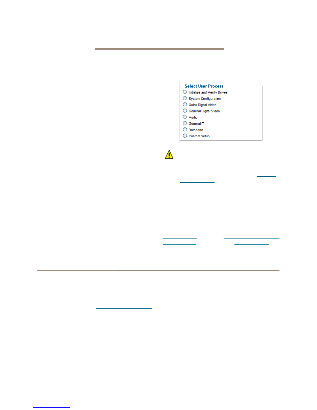
4The Manage Menu page appears. From the
Select User Process box, select the operation
you wish to perform.
Creating RAID groups
1 Follow the instructions in Preliminary steps on
page 34 and click on the RAID Groups arrow
from the Select User Process box.
2 Click on Create RAID Group.
3 Follow the directions as found in Selecting an
application on page 16 or Creating a custom
setup on page 18.
Deleting RAID groups
1 Follow the instructions in Preliminary steps on
page 34 and click on the RAID Groups arrow
from the Select User Process box.
2 Click on Delete RAID Groups.
3 Click on Next.
4 If you want to delete Hot Spares, click on the
appropriate radio button. (Refer to FastStream
process: adding or removing Hot Spares on
page 37.)
5 Click on each RAID group to be deleted.
6 Click the Delete button.
7 When you have selected all the groups to be
deleted, click Commit.
8 A warning box appears.
34
Page 40

If you want to continue click Yes. The
configuration completes and the Health and
Status Monitor page appears.
If you wish to start over, click No.
Adding drives to a RAID group
If you have unallocated drives, you can increase the
number of drives used by an existing RAID group by
adding an unallocated drive to the group. The new
drive is set up in a separate partition within the RAID
group. You may have to add more than one drive
depending on the RAID group setup.
1 Follow the instructions in Preliminary steps on
page 34 and click on the RAID Groups arrow
from the Select User Process box.
2 Click on Add Drives to a RAID Group.
3 Click Next.
4 Select the RAID group you wish to add the
drives to from the drop down menu.
5 Click on the drives you wish to add to your RAID
group.
1 Follow the instructions in Preliminary steps on
page 34 and click on the RAID Groups arrow
from the Select User Process box.
2 Click on Add Mirrors to a RAID Group.
3 Click Next.
4 Select the RAID Level 1 group you wish to add
the mirror drive to from the drop down menu.
5 Select the drive you wish to add.
CAUTIONCAUTION
Adding drives to an existing RAID group
may adversely impact performance. You
cannot reverse this operation unless you
delete the RAID group.
6 When you have completed your changes, click
on Commit.
7 A warning box appears. In the warning box,
verify that you want to complete the
configuration by clicking on Yes. Clicking on No
ends the procedure without making a change.
8The Health and Status Monitor page appears.
CAUTIONCAUTION
Adding drives to an existing RAID group
may adversely impact performance. You
cannot reverse this operation unless you
delete the RAID group.
6 When you have completed your changes, click
on Commit.
7 A warning box appears noting that informat ion
on the added drives is erased. Back up all data
on the new disks before proceeding. In the
warning box, verify that you want to complete
the configuration by clicking on Yes. Clicking on
No ends the procedure without making a
change.
8The Health and Status Monitor page appears.
9 Depending on how the drives are added, when
the process completes, the added drives may
be in a separate, new partition within the RAID
group
Adding mirrors to a RAID configuration
To increase data protection in RAID Level 1 groups,
you may add additional mirrors from unallocated
storage. Also known as n-way mirroring, adding
mirrors can only be performed if no other
Add Mirror
performed.
or
RAID Migration
operations are being
Add Drives,
Changing RAID configuration: RAID
migration
If you have unallocated drives, you can use them to
change the RAID Level of an existing RAID group. The
following migration levels are supported:
• JBOD to RAID Level 0
• JBOD to RAID Level 1
• RAID Level 0 to RAID Level1+0
• RAID Level 1 to RAID1+0
1 Follow the instructions in Preliminary steps
page 34 and click on the RAID Groups arrow
from the Select User Process box.
2 Click on the RAID Migration button.
3 Click on Next.
4 Follow the on-screen directions.
CAUTIONCAUTION
Adding drives to an existing RAID group
may adversely impact performance. You
cannot reverse this operation unless you
delete the RAID group.
5 When you have made your changes, click on
Commit.
6 A warning box appears. In the warning box,
verify that you want to complete the
configuration by clicking on Yes. Clicking on No
ends the procedure without making a change.
7The Health and Status Monitor page appears.
on
35
AT TO Technology Inc. FastStream SC Installation and Operation Manual
Page 41

Modifying RAID group mapping
You may change the LUNs of drives manually or let
the ExpressNA V S torage Manager map drives for you.
1 Follow the instructions in Preliminary steps on
page 34 and click on the RAID Groups arrow
from the Select User Process box.
2 Click on the Modify RAID Group Mapping
button.
3 Click on Next.
4 Select the RAID group you wish to change from
the drop down box.
5 Select the method you wish to use to map the
partitions. Refer to Modifying RAID group
partitions below.
• If you select Auto, all mapping for all RAID
groups attached to this FastStream is
changed, destroying any previous mapping.
• If you do not wish to change the mapping of
your other RAID groups, select Manual.
Click on any partition to map that partition to
a Port and LUN.
6 Click on Commit to save the new mapping.
7 A warning box tell you some mapping
configurations may impair performance.
Complete the mapping change by clicking on
Yes. Clicking on No ends the procedure without
making a change.
8The Health and Status Monitor page appears.
Modifying RAID group partitions
A RAID group may have several Terabytes of total
data capacity because of the size of the included
drives. Partitions allow you to break up large RAID
groups into smaller, more manageable groups.
Most host systems can address only 2 TB per LUN.
Partitioning increases storage efficiency by providing
more LUNs without using lower capacity RAID groups.
Partitioning allows the creation of multiple logical
volumes.
1 Follow the instructions in Preliminary steps on
page 34 and click on the RAID Groups arrow
from the Select User Process box.
2 Click on the Modify RAID Group Partitioning
button.
3 Click Next.
4 Select the RAID Group Name from the drop
down menu.
5 Using the graphic and drop down boxes,
choose to either merge or split existing
partitions or to assign different values for the
partition sizes.
6 Click Commit.
7 A warning box appears. In the warning box,
verify that you want to complete the
configuration by clicking on Yes. Clicking on No
ends the procedure without making a change.
8The Health and Status Monitor page appears.
Rebuilding RAID groups
If RAID groups become compromised in some
fashion, you must rebuild them.
If you have previously enabled Auto-Rebuild and
unallocated drives or Hot Sp ares are available, one of
those drives is substituted for the failed drive and a
rebuild takes place automatically.
Refer to
page 18 for information on Auto-Rebuild and to
FastStream process: adding or removing Hot
Spares
Hot Spares, if available, are used first, regardless of
the Auto-Rebuild setting.
If you have not enabled Auto-Rebuild and no Hot
Spares are ava ilable, use this procedure to rebuild the
faulted RAID group.
1 Follow the instructions in Preliminary steps on
2 Click on the Rebuild RAID Groups button.
3 Click on Next.
4 Select the RAID group you wish to rebuild.
5 If you have enabled RAID 6, choose to rebuild
6 Follow the on-screen directions, ending by
7 A warning box appears. In the warning box,
8The Health and Status Monitor page appears.
Step 18
on page 37 for information on Hot Spares.
page 34 and click on the RAID Groups arrow
from the Select User Process box.
one or two drives at the same time.
clicking on Commit.
verify that you want to complete the rebuild by
clicking on Yes. Clicking on No ends the
procedure without making a change.
under
Creating a custom setup
on
36
Page 42

Modifying RAID options
You may change Auto-Rebuild, SpeedRead and
Prefetch configurations. Refer to
setup
on page 18 for details on these features.
1 Follow the instructions in Preliminary steps on
page 34 and click on the RAID Groups arrow
from the Select User Process box.
Creating a custom
2 Click on the Modify RAID Options button.
3 Click on Next.
4 Select the RAID group from the drop down box.
5 Select the options you wish to change.
6 Click on Commit.
FastStream process: adding or removing Hot Spares
If a member of a RAID group becomes degraded or
faulted, you lose some redundancy in your RAID
group until a new member is rebuilt into the RAID
group. However, Hot Spare devices may be
designated as replacements for faulted devices
without intervention by you or a host.
You may set up a pool of Hot Spare devices of
different sizes appropriate for your RAID groups.
Hot Spares may be set up by the FastStream
automatically depending on your choices during initial
setup. There are two types of Hot Spares:
• Dedicated: Hot Spares that are dedicated solely
for use with a specific RAID group and may not
be used by any other RAID group
• Global: Hot Spares that may be used by any
RAID group.
Note
Devices in the Hot Spare pool should be of
appropriate size to the RAID group so that
smaller devices are not replaced by much
larger Hot Spare devices, thus wasting
storage capacity.
Drives will be searched for in this order:
1 Search for Dedicated Hot Spare
2 Search for Global Hot Spare (Smallest
available drive of sufficient size)
When the ATTO FastS tream detects a faulted device:
• The FastStream replaces the faulted device with
the device from the Hot Spare pool.
• The FastStream begins an automatic rebuild of
the RAID group(s).
Note
A RAID rebuild may take up to two hours to
complete.
1 Follow the instructions in Preliminary steps on
page 34 and click on the FastStream SC arrow
from the Select User Process box.
2 Select the Add/Remove Hot Spares button.
3Select Designated or Global Hot Spares.
4If Designated is selected, user will be
prompted to select the RAID Group.
5 Select the drive(s) to be added or removed from
the Hot Spare pool by clicking on the boxes
representing those drives.
6 When you have completed your changes, click
Commit.
7 A warning box appears. In the warning box,
verify that you want to complete the
configuration by clicking on Yes. Clicking on No
ends the procedure without making a change.
8The Health and Status Monitor screen
appears.
37
AT TO Technology Inc. FastStream SC Installation and Operation Manual
Page 43

Removing RAID configuration data
If you move single drives between FastStreams
without erasing the drives, you should clean stale
RAID configuration data from the drives, permanently
removing the drive from the RAID group. This
operation can be performed on drives that belong to a
RAID group now or have once belonged to a RAID
group and are labeled
CAUTIONCAUTION
Continue with extreme caution: data is lost
on the drive when it is cleaned of RAID
information.
1 If you are not already in the ExpressNAV
Storage Manager, type the IP address of your
controller in a standard browser. On the splash
screen, click Enter Here. In the box provided,
type in your user name and password, and click
OK.
2 Click the Diagnostics button on the Menu
Items list on the left hand side of the
ExpressNAV Storage Manager.
Replaced
after system scans.
Advanced CLI page
3 Click in the Clean RAID Configuration data
radio button from the Select User Process
box.
4 Click Next.
5 Click on the drives you wish to update; the
drives are highlighted.
6 Click on Commit.
7 A warning box appears. In the warning box,
verify that you want to complete the
configuration by clicking on Yes. Clicking on No
ends the procedure without making a change.
8 When the process is complete, the Health and
Status Monitor screen appears.
Changes to various parameters may be made using
the
Advanced
CAUTIONCAUTION
Do not use this page unless you are
directed to by an ATTO technician.
Changing parameters may cause loss of
data and/or disruption to the performance
and reliability of the FastStream.
The ExpressNAV Storage Manager is the
preferred method to manage the FastStream.
1 If you are not already in the ExpressNAV
Storage Manager, type the IP address of your
controller in a standard browser. On the splash
screen, click Enter Here. In the box provided,
page.
Note
type in your user name and password, and click
OK.
2 In the left-hand menu, click on the Advanced
menu item.
3The Advanced CLI Configuration page
appears. Wait for the
in the CLI command in the text box provided.
Refer to CLI Provides an ASCII-based Interface
on page i of the Appendix.
4 Click the Submit button: this is equivalent to
typing in the CLI command into a telnet or serial
port CLI session.
A text field beneath the box lists the most recent
commands issued to the FastStream through this
page. If you enter an incorrect parameter , the CLI help
text is displayed, showing the parameters available.
An asterisk next to the
must type
for changes to take effect.
SaveConfiguration restart
Ready prompt, then type
Ready
prompt indicates you
in the text box
38
Page 44

8.0 Manage ATTO Devices, Configurations
You may save the current con figuration of your FastStream SC, use a configuration from anoth er FastS tream, or
change the configurations of other ATTO devices from your current browser using the ExpressNAV Storage
Manager.
If you have other ATT O devices in the same broadcast
domain with no routers between them, and any
switches between this FastStream and the other
devices are configured to forward UDP broadcast
messages, you may physically identify these devices
and manage them from within the browser you are
currently using.
You may also save the configuration of the
FastStream you are currently using, or restore it from
a previously-saved configuration, or import a
configuration from another ATTO FastStream.
It is best practice to give your current FastStream a
recognizable name so that you can distinguish it more
easily from among other ATTO devices.
Creating a unique name for your FastStream
You may wish to name your FastStream if you are
going to manage several ATTO devices from one
browser.
1 If you are not already in the ExpressNAV
Storage Manager, type the IP address of your
controller in a standard browser. On the splash
screen, click Enter Here. In the box provided,
type in your user name and password, and click
OK.
2The Monitor page appears. In the left-hand
menu, click on the Manage menu item on the
left side of the screen.
3 Click on the Other Devices arrow.
4 In the Other Devices menu, click on Set
Controller Name.
5 Click on Next.
6The System Configuration page appears.
Type in a name for your controller in the text
box provided.
7 Click Commit. The name you typed appears in
the upper right corner of the screen under the
ATTO FastStream SC banner.
Discovering, managing other ATTO devices
1 Follow steps 1-3 in Creating a unique name for
your FastStream above.
2 Click on the Find ATTO Devices button.
3 Click Next.
4 Click on the Rescan button.
5 Select a device from the list. An arrow points to
the controller you are currently using.
39
AT TO Technology Inc. FastStream SC Installation and Operation Manual
6 Press the Identify button to activate a blinking
LED on the selected product. Click on the listed
device again to stop the blinking LED.
7 Click on the device from the list and click on the
Launch in Browser button to view the device's
management console.
Page 45

Saving or restoring a configuration
Y ou may save the configuration of the FastS tream you
are currently using, restore the configuration from a
previously-saved configuration for that FastStream, or
clone a configuration from another ATTO FastStream
using the Save/Restore feature.
Note
It is best practice to save a copy of your
configuration settings to a file to easily replace
a unit or to set up additional controllers.
1 Follow steps 1-2 in Creating a unique name for
your FastStream above.
2 Click on the FastStream SC arrow.
3 Click on the System Configuration
Save/Restore button.
4 Click on Next.
5 Choose the option you wish to use.
CAUTIONCAUTION
If you perform a full restore on multiple
FastStream storage controllers on the
same SAN, you will have World Wide Name
conflicts. Use a partial restore to keep
unique WWNs on your SAN.
6 Click on Commit.
7 A warning box appears. If you wish to continue
with the changes you have chosen and restart
your FastStream, select Yes. If you do not wish
to make the changes, select No.
Exhibit 8.0-1 The System Configuration Save/Restore page.
40
Page 46

9.0 Interface Options
The best way to manage, monitor and configure the FastStream is to use the ExpressNAV Storage Manager, a
browser-based application included with your FastStream, but you may use a terminal emulation program or
Telnet.
Using the ExpressNAV Storage Manager
Use the ExpressNAV Storage Manager to manage,
monitor and configure the unit. The choices you make
lead you from screen to screen. Choices which are not
available are greyed out.
Note
The FastStream is initially configured with
DHCP enabled. It is best if you have access to
a DHCP server.
1 Work from the computer attached to the
FastStream Ethernet port. From the CD
supplied with your FastStream, run the
QuickNav Utility QuickNAV-windows.exe for
Windows or QuickNAV-Mac for Mac OS X.
2 Locate the FastStream with the serial number
recorded earlier.
3 Highlight the serial number.
4 Click Next.
If a DHCP server is available on your network,
an address is assigned automatically by the
server. Note the assigned address:
_____________________________________
If you do not have a DHCP server, get an IP
address and subnet mask from your network
administrator, type it into the area provided, and
click on Next.
5 Click on Launch Browser.
Your browser points to the ATTO ExpressNAV
splash screen. Press Enter.
6 Type in the user name and password values.
Note
The default values are user name:
password:
insensitive and the password is case sensitive.
It is best practice to change the user name and
password. Refer to
name, password
The pages which next appear depend on whether or
not you have begun configuring the FastStream.
Password
Changing current user
on page 21.
. The user name is case
root
and
41
ATTO Technology Inc. FastStream SC RAID Controller Installation and Operation Manual
Page 47

Using the serial port
To connect to a terminal emulation program to
manage the FastStream, use the serial port.
1 Connect a cable from FastStream RS-232
serial port or header to the serial (COM) port on
a personal computer.
2 Start a terminal emulation program on the
personal computer, and use it to connect to the
FastStream. For example, if you are using
Hyper Terminal on a computer running a
Windows operating system,
a. Type FastStream in the New Connection
dialog box.
b. Click OK.
c. In the Connect To dialog box in the
Connect using field, select the COM port
number to which your serial cable is
connected.
d. Click OK.
e. In the COM Properties dialog box select the
following values:
• Bits per second: 115200
• Data Bits: 8
• Parity: None
• Stop Bits: 1
• Flow Control: None
• Terminal type: ASCII
• Echo: off
f. Click OK.
3 Turn on the FastStream.
4 After you connect to the FastStream, start-up
messages are displayed. The last line in the
start-up message sequence is Ready.
Make adjustments to the FastStream using the
Command Line Interface as described in CLI
Provides an ASCII-based Interface on page i of
the Appendix.
Note
In serial port sessions, there is no prompt on
the line below the word
commands in the blank line where the cursor
is resting. No user name or password is
required for serial port access.
5 To verify that you have connected successfully,
type help after the Ready prompt and press
Enter.
If a list of all available commands does not
appear on the screen, review the steps in this
section, check the cable, or contact service
personnel until the problem is solved.
If you have difficulty using the serial port, verify
that you have the correct settings and that your
serial cable is less then two meters in length.
Ready
. Begin typing
Using Telnet
Up to three Telnet sessions using the FastStream
Ethernet management port can be conducted
simultaneously. A serial port session can use the CLI
while Telnet sessions are open. Whichever session
issues the first
SaveConfiguration
commands, while the other sessions can only issue
get
commands or display information.
Once a connection is established, refer to
Provides an ASCII-based Interface
Appendix.
1 Connect to the FastStream from a computer on
the same Ethernet network.
2 Start a Telnet session.
set
CLI command that requires a
can continue to issue
on page i of the
set
CLI
Note
There is more than one way to connect to the
FastStream using a telnet program.Y our telnet
program may operate differently than in the
following instructions.
3 At the telnet prompt, issue the open command
where x.x.x.x is the IP address of the
FastStream.
telnet > open x.x.x.x
4 If you have to specify a port type, type in the
port type “telnet” and the terminal type “SC100”.
port type: telnet
terminal type: SC100
5 Type in the default values for the user name,
root, and the password, Password, if you did
not set new values in Changing current user
name, password on page 21.
42
Page 48

10.0 Update Firmware
Firmware updates are available on the ATTO website. Contact your ATTO sales representative for complete
information.
The ATTO FastStream has several processors which
control the flow of data. The firmware to control these
processors can be upgraded in the field using the
ExpressNAV Storage Manager.
Be sure all data is backed up before updating firmware
to prevent data loss.
CAUTIONCAUTION
Ensure that all I/O to the A TT O FastStream
has stopped. During this procedure, do not
interrupt the update process.
1 The ATTO FastStream firmware is distributed
as an image file (.ima). Download the
appropriate firmware file from the ATTO
website or insert the Installation CD containing
the file into your computer.
2 If you are not already in the ExpressNAV
Storage Manager, type the IP address of your
controller in a standard browser. On the splash
screen, click Enter Here. In the box provided,
type in your user name and password, and click
OK.
3The Health and Status Monitor page appears.
4 Click on the Diagnostics button on the left
hand side of the ExpressNAV Storage
Manager.
5The Diagnostics Menu page appears. From
the Select User Process box, select Update
the Firmware.
6 Click Next.
7 If you know the name and location of the .ima
file, enter it into the text box provided. If you do
not know the file name and location, click on
Browse to navigate to the new firmware and
click on it until the filename appears in the text
box.
8 Click Upload.
CAUTIONCAUTION
Do not power down the host or the ATTO
FastStream. Interrupting the update
process makes your FastStream
inoperable and you must return it to ATTO
for repair.
9 Wait for a success message to be displayed.
10 Click on Restart.
11 When the Diagnostics Menu page appears
43
AT TO Technology Inc. FastStream SC Installation and Operation Manual
your new firmware has been uploaded and
installed.
Page 49

Appendix A CLI Provides an ASCII-based Interface
The command line interface (CLI) uses ASCII commands typed while in CLI mode.
CAUTIONCAUTION
Do not use CLI unless you are directed to
by an ATTO technician.
Changing parameters may cause loss of
data and/or disruption to performance and
reliability of the FastStream.
The ExpressNAV Storage Manager is the
preferred method to operate and manage
the FastStream. Refer to
ExpressNAV Storage Manager
for details.
The command line interface (CLI) is a set of ASCIIbased commands which perform configuration and
diagnostic tasks.You may use them through the
ExpressNAV Storage Manager Advanced CLI page
(refer to
the serial port interface or the Ethernet management
port (refer to
• CLI commands are context sensitive and
[Get|Set] Command [Parameter1|Parameter2]
followed by the return or enter key.
• CLI commands are case insensitive: you may
Advanced CLI page
Interface Options
generally follow a standard format
type all upper or all lower case or a mixture.
Upper and lower case in this manual and the
help screen are for clarification only.
Using the
on page 41
on page 38) or by using
on page 41).
• Commands generally have three types of
operation: get, set and immediate.
• The get form returns the value of a parameter or
setting and is an informational command.
• Responses to get commands are followed by
Ready.
• The set form is an action that changes the value
of a parameter or configuration setting. It may
require a SaveConfiguration command and a
restart of the system before it is implemented.
The restart can be accomplished as part of the
SaveConfiguration command or by using a
separate FirmwareRestart command. A
number of set commands may be issued before
the SaveConfiguration command.
• Responses to set commands are ei ther an error
message or Ready. *. The asterisk indicates
you must use a SaveConfiguration command
to finalize the set command.
• Set commands which do not require a
SaveConfiguration command are immediately
executed.
Note
Using certain CLI commands during normal
operation can cause a performance drop.
Once command actions are complete,
performance should return to normal levels.
Exhibit A-1 Symbols, typefaces and abbreviations used to indic ate fun ctions and elements of the
command line interface used in this manual.
Symbol/Abbreviation Indicates
- A range (6 – 9 = 6, 7, 8, 9)
... Indicates optional repetition of the preceding item
[ ] Required entry
| Pick one of
< > Optional entry
BlockDevID Index designation of a block as found by using the BlockDevScan
EnclosureIndex Index designation of an enclosure found by using the SESIdentify
fl Fibre Channel LUN ID (0 <= fl <= 31)
fp Fibre Channel port number (1 <= fp <= 2)
command
command
i
Page 50

Symbol/Abbreviation Indicates
GroupName The name of the RAID group, designated by the user, to which a block
device is assigned. Use RGDisplay <GroupName | all>
group names
MemberIndex Index designation of a RAID group member as found by using the
RMStatus
mp1 Ethernet port used to manage the FastStream
PartitionIndex Index designation of a partition as found by using the PartitionDisplay
command
command
CLI error messages
The following error messages may be returned by the Command line Interface:
ERROR. Invalid Command. Type 'Help' for command list.
ERROR. Wrong/Missing Parameters
Usage: <usage string>
ERROR Invalid RAID Group state
ERROR Invalid Block Device index
ERROR Invalid RAID Member index
ERROR Maximum number of RAID Groups exceeded
ERROR Insufficient number of RAID Group members
ERROR
Block Device at specified index no longer available
ERROR Insufficient RAID Group members for RAID type
to discover RAID
CLI summary
The following chart summarizes the Command Line Interface commands, their defaults, and an example of how
to enter the commands. Commands which have no default values have a blank entry in that column of the table.
CAUTIONCAUTION
Do not use CLI unless you are directed to by an ATTO technician.
Changing parameters may cause loss of data and/or disruption to performance and reliability of
the FastStream.
The ExpressNA V Storage Manager is the preferred method to operate and manage the FastStream.
Refer to
Command Default Example
AutoMap automap
AutoResume initialize = enabled
BlockDevClean blockdevclean 30
BlockDevIdentify blockdevidentify alpha 3
BlockDevIDStop blockdevidstop
BlockDevScan blockdevscan
BootDelay 5 set bootdelay 25
Interface Options
on page 41 for details.
set autoresume all disabled
rebuild = enabled
erase = disabled
ii
AT TO Technology Inc. FastStream SC Installation and Operation Manual
Page 51

Command Default Example
BridgeModel get bridgemodel
BridgeName “ “ set bridgename Omega6
ClearEventLog cleareventlog
Date set date 03/03/2003
DefaultInterleave 128 set defaultinterleave 64
DeleteAllMaps deleteallmaps
DisplayEventLog displayeventlog
DisplayEventLogFilter all all all set displayeventlogfilter gen info all
DriveTest drivetest begin
DriveTestConfig set drivetestconfig read
DriveTestList set drivetestlist all
DriveTestStatus get driveteststatus
DumpConfiguration dumpconfiguration
DumpEventLog dumpeventlog
EmailFromAddress set emailfromaddress
EmailNotify disabled set emailnotify enabled
EmailNotifyAddress get emailnotifyaddress
EmailPassword set emailpassword
EmailServerAddress 0.0.0.0 get emailserveraddress
EmailUsername get emailusername
EthernetSpeed auto set ethernetspeed mp1 100
EventLog enabled set eventlog disabled
EventLogFilter all all all set eventlogfilter gen info all
Exit exit
FCConnMode loop set fcconnmode all ptp
FCDataRate auto get fcdatarate all
FCHard disabled set fchard enabled
FCHardAddress fp1=3; fp2=4, fp3=5, fp4=6 set fchardaddress 1 122
FCMultiNode disabled set fcmultinode enabled
FCPortErrors get fcporterrors all
FCPortList fcportlist
FCWWName get fcwwname 1
FirmwareRestart firmwarerestart
Help help driveinfo
HSAdd hsadd 3
HSDisplay hsdisplay
HSRemove hsremove 3
IdentifyBridge disabled set identifyBridge enabled
Info info
iii
Page 52

Command Default Example
IPAddress 10.0.0.1 get ipaddress mp1
IPDHCP enabled set ipdhcp mp1 disabled
IPDNSServer set ipdnsserver mp1 172.15.12.123
IPGateway 0.0.0.0 get ipgateway mp1
IPSubnetMask 255.255.0.0 get ipsubnetmask mp1
IsReserved isreserved
MaxOpTemp 70 get maxoptemp
Metrics metrics display all
MinOpTemp 0 set minoptemp 10
OpTempWarn 5 set optempwarn 15
Partition partition alpha1 6 4 GB
PartitionDisplay partitiondisplay alpha1
PartitionMerge partitionmerge alpha1 all
PartitionWriteCache set partititionwritecache g1 1 enabled
PartitionSplit partitionsplit alpha1 22 2
PassThroughMode disabled set passthroughmode all
PassThroughPersistent passthroughpersistent
PassThroughRediscover passthroughredicsover
Password Password set password
Performance get performance 2
Ping ping mp1 192.42.155.155
RAIDRebuildPriority same set raidrebuildpriority low
RAIDSpeedWriteLimit 8 set raidspeedwritelimit 20
ReadOnlyPassword Password set readonlypassword
ReadOnlyUsername user set readonlyusername
Reserve reserve
ResetFCPortErrors resetfcporterrors 1
RestoreConfiguration restoreconfiguration default
RGAddStorage rgaddstorage g1 span commit
RGAutoRebuild disabled
RGCancelAddStorage rgcanceladdstorage g1
RGCommit rgcommit all
RGCreate rgcreate g1 raid0
RGDelete rgdelete g1
RGDiskWriteCache set rgdiskwritecache g1 enabled
RGDisplay rgdisplay all
RGErase rgerase g1
RGHaltConversion rghaltconversion g1
RGHaltErase rghalterase g1
set rgautorebuild g1 enabled
iv
AT TO Technology Inc. FastStream SC Installation and Operation Manual
Page 53

Command Default Example
RGHaltInitialization rghaltinitialization g1
RGHaltRebuild rghaltrebuild g1
RGMemberAdd rgmemberadd g1 22
RGMemberRemove rgmemberremove g1 22
RGPreFetch 0 rgprefetch g1 2
RGRebuild rgrebuild g1
RGResumeConversion rgresumeconversion g1
RGResumeErase rgresumeerase g1
RGResumeInitialization rgresumeinitialization g1
RGResumeRebuild rgresumerebuild g1
RGSectorSize 512 rgsectorsize g1 8192
RGSpanDepth 1 set rgspandepth g1 spandepth 22
RGSpeedRead auto set rgspeedread g1 enabled
RGUnmap rgunmap g1
RGWaitTimeout 5 rgwaittimeout 30
RMStatus rmstatus g1
Route route fc 1 0 raid alpha1 6
RouteDisplay routedisplay fc
SASTargets sastargets
SaveConfiguration saveconfiguration restart
SerialNumber get serialnumber
SerialPortBaudRate 115200 set serialportbaudrate 19200
SerialPortEcho enabled get serialportecho
SES enabled set ses disabled
SESAlarmTest sessalarmtest 22 set
SESDiskFailureAlarm disabled set sesdiskfailurealarm enabled
SESEnclosures sesenclosures
SESIdentify set sesidentify RAID g1
SESIdentifyStop sesidentifystop all
SESMute mute sesmute remind
SESPoll 60 set sespoll 20
SESStartingSlot 1 set sesstartingslot 2
SESStatus sesstatus
SNTP enabled get sntp
SNTPServer 192.43.244.18 set sntpserver 129.6.15.28
Ta ilEventLog taileventlog
Temperature get temperature
Time set time 03:32:30
TimeZone EST set timezone pst
v
Page 54

Command Default Example
Username root set username Barbara
VerboseMode enabled set verbosemode disabled
VirtualDriveInfo virtualdriveinfo
WrapEventLog enabled set wrapeventlog disabled
zModem zmodem receive
CLI command explanations
Command Line Interface commands are listed alphabetically with explanations of what they are used for, their
defaults and syntax.
CAUTIONCAUTION
Using CLI without contacting an ATTO
technician is not recommended because
changing parameters may cause loss of
data and/or disruption to performance and
reliability of the FastStream.
The ExpressNAV Storage Manager is the
preferred method to manage the
FastStream. Refer to
Interface Options
on
page 41 for deta ils.
AutoMap
Automatically assigns a subset of source protocol LUNs to a
subset of target destination devices visible to the unit. The unit
reports a five-second delay while it scans for devices. All
previous maps are deleted.
If
FCMultiNode
is enabled (multiple node):
AutoMap <fp>
SaveConfiguration command required
If
FCMultiNode
is disabled (single node): AutoMap
SaveConfiguration command required
AutoResume
Regulates the
and erase operations at startup. If no group name is specified,
all existing RAID groups are affected.
Default: enabled for AutoResume Rebuild, Initialize
set AutoResume [Rebuild | Erase |Initialize | All ] [enabled
| disabled] <group name>
AutoResume
features for interrupted rebuild
disabled for AutoResumeErase
BlockDevClean
Removes any RAID configuration data from the block device
with the specified block ID.
CAUTIONCAUTION
All RAID group setup information is lost
and you lose all RAID group data.
BlockDevClean [BlockDevID]
BlockDevIdentify
Lights the LED of a disk drive. Use either RAID group name and
member index, or block ID.
BlockDevIdentify <Group name> [BlockDevID | member
index]
BlockDevIDStop
T urns off the IO LED of a previously identified disk drive.
BlockDevIDStop
BlockDevScan
Lists all currently-connected physical block devices and any
potential RAID group association. Each block device listed is
assigned a unique index at the time of the scan which is used to
identify block devices for other CLI operations.
BlockDevScan
Boot Delay
Regulates the delay (in seconds) which the unit waits after
startup before allowing hosts to detect target devices. The value
0 produces no delay.
Default: 5
set BootDelay [0-255]
get BootDelay
BridgeModel
Reports specific model and firmware information.
get BridgeModel
vi
AT TO Technology Inc. FastStream SC Installation and Operation Manual
Page 55

BridgeName
Specifies an ASCII name assigned to the unit to identify
individual units. It is not the World Wide Name. Changes take
effect immediately. The name may be contain up to 8
characters.
set BridgeName [name]
SaveConfiguration Restart command required
get BridgeName
ClearEventLog
Clears the contents of the
recorded until the operation is completed.
ClearEventLog
EventLog
. No new entries are
Date
Regulates the current date for this unit. The date range is
1/1/2000 to 12/31/2099.
set Date [MM] / [DD] / [YYYY]
get Date
DefaultInterleave
Assigns or retrieves the system’s default interleave size (in 512byte blocks) for new RAID groups (before
been used). If an interleave size is not explicitly specified when
a RAID group is created, then the
used instead.
RGCommit
DefaultInterleave
has
value is
Default: 128
set DefaultInterleave [16 | 32 | 64 | 128 | 256 | 512 | 1024
| 2048]
SaveConfiguration Restart command required
get DefaultInterleave
DeleteAllMaps
Removes all mapped devices from the map table. Upon the
subsequent POST, the default maps are loaded if no maps are
present.
DeleteAllMaps
SaveConfiguration command required
DisplayEventLog
Displays the
DisplayEventLogFilter
the number of lines to be displayed as a single page with no user
interaction. After the command has executed, use
scroll through the log. Type
command.
DisplayEventLog <n>
EventLog
.The event log may be filtered using the
command. The optional parameter n is
+, -
or = to
quit
and press
Enter
to exit the
DisplayEventLogFilter
Filters the display of data for specified subsystems and levels
DisplayEventLog
during
entries are platform-dependent. For set commands, the final
parameter indicates whether or not events from the specified
subsystem and level are displayed.
mode. Valid event log subsystem
Default: all all all
set DisplayEventLogFilter [subsystem | all] [level | all] [all
| none]
get DisplayEventLogFilter [subsystem |all] [level | all]
DriveTest
Starts or stops a drive test with the previously-specified
configuration and drive list. Drives which are in-use by the test
are not available for RAID configuration or RAID operations.
Only one test can be run at a time.
DriveTest [Begin | Cancel]
DriveTestConfig
Configures the next drive test to perform: initialize (destructive
write-only), read (non-destructive read-only), verify (destructive
verify), or init-verify (destructive write-read-verify).The test is not
started until the
DriveTest Begin
command is given.
set DriveTestConfig [init | read | verify | init-verify]
get DriveTestConfig
DriveTestList
Specifies drives to be run in the next drive test. This command
can be called with different eligible block IDs and each one is
added to the list. Drives which are not part of a RAID group or
all
are not hot spares are eligible. The
chooses eligible drives. The test is not started until the
DriveTest Begin
command is given.
parameter automatically
set DriveTestList [drive [BlockDevID] | all]
get DriveTestList
DriveTestStatus
Displays the status of the currently running drive test, but does
not display performance metrics. If a block device ID is not
idle
running or cannot be found, its state is
complete is
0
.
and percent
get DriveTestStatus <drive [BlockDevID]>
DumpConfiguration
Displays the unit’s configuration to the
ExpressNAV S torage Manager or a terminal emulation or telnet
session. The record may not be displayed completely in the
ExpressNAV page.
DumpConfiguration
Advanced
page of the
vii
Page 56

DumpEventLog
Displays the contents of the
the ExpressNAV Storage Manager or a terminal emulation or
telnet session. The record may not be displayed completely in
the ExpressNAV page.
DumpEventLog
EventLog
to the Advanced page of
EmailFromAddress
Configures the Email address that the unit uses to communicate
with the Email server. Full Email address is a fully qualified
Internet Email address, not more than 128 characters long.
set EmailFromAddress [full email address]
get EmailFromAddress
EmailNotify
Regulates Email notification.
Default: disabled.
set EmailNotify [enabled | disabled]
get EmailNotify
EmailNotifyAddress
Configures notification addresses. Index is a number between 1
Full Email address
and 5.
address, not more than 128 characters long. Emails are sent
based on the warning level you set to trigger an Email alert.
is a fully qualified Internet Email
Warning levels
None: no Emails
Critical: only critical severity events
Warning: warnings and critical events
Informational: information
All: all warnings, critical events and informational
messages
set EmailNotifyAddress [index] [full email address]
[warning level]
get EmailNotifyAddress <index | all>
EmailPassword
Configures the password which authenticates the login to the
SMTP Email server. The password must not be more than 64
characters. A password is not required if the Email server does
not require authentication.
set EmailPassword
SaveConfiguration command required
EmailServerAddress
Configures the address of the server the unit must contact in
order to send out Email notifications using either an Email
address (xxx.xxx.x.x) or a fully qualified domain name
(mal.myserver.com).
Default: 0.0.0.0
set EmailServerAddress [IP address |domain name]
SaveConfiguration command required
get EmailServerAddress
EmailUsername
Configures the user name which authenticates the login to the
SMTP Email server. The user name must not be more than 128
characters. A user name is not required if the Email server does
not require authentication.
set EmailUsername [username]
SaveConfiguration command required
get EmailUsername
EthernetSpeed
Regulates the speed of the unit’s Ethernet port(s). If
enabled, the Ethernet speed is negotiated. When hard set, 10
and 100 speeds are half duplex.
Default: auto
set EthernetSpeed [mp1] [10 | 100 | auto]
SaveConfiguration Restart command required
get EthernetSpeed [mp1]
Auto
is
EventLog
Regulates event logging. When enabled, the unit records
various system events to the event log.
Default: enabled
set EventLog [enabled | disabled]
get EventLog
EventLogFilter
Filters data from specific unit subsystems and levels when
EventLog
platform-dependent. For set commands, the final parameter
indicates whether or not events from the specified subsystem
and level are displayed.
Default: all all all
set EventLogFilter [subsystem | all] [ level | all] [all | none]
get EventLogFilter [subsystem| all ] [level | all]
is enabled. The specific entries supported are
viii
AT TO Technology Inc. FastStream SC Installation and Operation Manual
Exit
T erminates the current CLI session over Telnet. This command
has no effect if used during a serial CLI session.
Exit
Page 57

FCConnMode
Specifies the connection mode the unit uses when
communicating across a Fibre Channel network.
Connection modes:
FC_AL arbitrated loop: loop
Point-to-point: ptp
auto-negotiation, loop preferred: loop-ptp
auto-negotiation, ptp preferred: ptp-loop:
Default: loop
set FCConnMode [fp| all] [loo p | ptp | lo op-ptp | ptp-loop]
SaveConfiguration Restart command required
get FCConnMode [fp | all]
new maps using the
AutoMap
or
Route
commands.
Default: disabled
set FCMultiNode [enabled | disabled]
get FCMultiNode
FCPortErrors
Displays the number of Fibre Channel errors that have occurred
since the last reboot/power-on or use of the
ResetFCPortErrors
get FCPortErrors [fp | all]
command.
FCDataRate
Specifies the Fibre Channel data rate at which operation will
occur. If no connection has been made, the data rate in the
command output toggles among 1Gb, 2Gb or 4Gb on hardware
capable of 4Gb per sec., and 8Gb on hardware capable of 8 Gb
per sec.
Info
set FCDataRate [fp | all] [1Gb | 2Gb | 4Gb | 8Gb | auto]
get FCDataRate [fp | all]
FCHard
Regulates Fibre Channel hard address assignment. When
enabled, the unit tries to use its internal hard address as its
address on the Fibre Channel loop. Under soft addressing, the
unit loop address is assigned during loop initialization.
Default: disabled
set FCHard [enabled | disabled]
SaveConfiguration Restart command required
get FCHard
FCHardAddress
Specifies the value used as the FC-AL hard address. This value
represents the address that will be used if the
command is enabled. Valid Fibre Channel hard address values
is from 0 through 125.
FCHard
set FCHardAddress [fp | all] [address]
get FCHardAddress [fp | all]
FCMultiNode
Determines the reported identity of Fibre Channel ports. When
enabled (multiple node mode), each port reports a separate
unique Node Name; logical units may be mapped to any port.
When disabled (single node), each port reports the same Node
Name and each logical unit map is applied to all ports.
Note
Changing the FC port reporting causes all
maps to be deleted: you must perform a
SaveConfiguration
command before creating
FCPortList
Displays a list of available FC ports and their current status.
Valid reported status values are
Reserved
and
Disabled.
Up, Down, Failed,
FCPortList
FCWWName
Reports the World Wide Port Name of the Fibre Channel
interface referenced. Each Fibre Channel port has an individual
and unique 8-byte Port Name.
get FCWWName [fp | all]]
FirmwareRestart
Resets and reinitializes the unit firmware. Use the
option to override any CLI reservations held by other sessions.
FirmwareRestart <forced>
forced
Help
Issued with no parameters displays a list of available CLI
commands. When a CLI command name is specified, a
command usage string and command description are
displayed.
Help <Command>
HSAdd
Assigns a Block Device to the Hot Spare pool. If RAID and RAID
group name are specified, the Hot Spare is assigned only to the
specified RAID group. If no group name is specified, the Hot
Spare is a global Hot Spare and available for use by any RAID
group.
HSAdd <RAID Group Name> [BlockDevID]
HSDisplay
Lists all devices in the Hot Spare pool.
HSDisplay
HSRemove
Removes a Block Device from the Hot Spare pool.
HSRemove [BlockDevID] [all]
ix
Page 58

IdentifyBridge
If you enable this command, the Fault LED on this unit blinks so
that hardware may be identified. Disabling this option cancels
the blinking..
Default: disabled
set IdentifyBridge [enabled | disabled]
get IdentifyBridge
Info
Lists version numbers and other product information for key
components. Use the optional
subset of system information.
Info <brief>
brief
to list a more concise
IPSubnetMask
Controls the current subnet masks used by any Ethernet port(s)
on the unit. If
current IP subnet mask assigned by the network DHCP server.
IPDHCP
is enabled, the get command reports the
Default: 255.255.0.0
set IPSubnetMask [mp1] [xxx.xxx.xxx.xxx]
SaveConfiguration Restart command required
get IPSubnetMask [mp1]
IsReserved
Lists the reservation status of the current services session or
interface use.
IsReserved
IPAddress
Controls the current IP address of the Ethernet port(s) on the
unit. If
IPDHCP
current IP address assigned by the network DHCP server,
followed by the (DHCP) identifier.
is enabled, the get command reports the
Default: 10.0.0.1
set IPAddress [mp1] [xxx.xxx.xxx.xxx]
SaveConfiguration Restart command required
get IPAddress [mp1]
IPDHCP
Regulates how the unit acquires its IP address. When disabled,
the unit uses the IP address specified by the
command; when enabled, the unit gets its IP address from a
DHCP server.
IPAddress
CLI
Default: enabled
set IPDHCP mp1 [enabled | disabled]
SaveConfiguration Restart command required
get IPDHCP
IPDNSServer
Controls the current DNS Server address. If
enabled, the DNS Server address is automatically detected. If
IPDHCP is disabled, you must set the address manually using
this command.
set IPDNSServer mp1 [xxx.xxx.xxx.xxx]
get IPDNSServer
IPDHCP
is
IPGateway
Controls the current default gateways used by any Ethernet
port(s) on the unit. If
reports the current IP gateway assigned by the network DHCP
server.
Default: 0.0.0.0
set IPGateway [mp1] [xxx.xxx.xxx.xxx]
SaveConfiguration Restart command required
get IPGateway [mp1]
IPDHCP
is enabled, the get command
MaxOpTemp
Regulates or lists the maximum operating temperature. Valid
°
entries are from 55 through 70
Celsius.
Default: 70
set MaxOpTemp [55 – 70]
SaveConfiguration Restart command required
get MaxOpTemp
Metrics
Controls the collection of standard data metrics within a product.
Metrics [St art | S top | Display | Clear] [[drive [BlockDevID]
| all | running]
MinOpTemp
Regulates or lists the minimum operating temperature. Valid
°
entries are from 0 through 15
Celsius.
Default: 0
set MinOpTemp [0 – 15]
SaveConfiguration Restart command required
get MinOpTemp
OpT empWarn
Regulates or lists the offset when a warning is issued before a
thermal control event. Valid entries are from 0 to 15°Celsius
degrees.
Default: 5
set OpTempWarn [0 – 15]
SaveConfiguration Restart command required
get OpTempWarn
Partition
Regulates the specified partition to the specified capacity in
gigabytes (GB), megabytes (MB), or blocks. The specified
capacity must be smaller than the specified partition's current
capacity. A new partition is created to acquire the remainder of
the original partition’s space.
Partition [Group Name] [PartIdx] [capacity] [GB | MB |
blocks]
x
AT TO Technology Inc. FastStream SC Installation and Operation Manual
Page 59

PartitionDisplay
Lists all partitions available in the specified RAID group in order
of contiguousness (as opposed to index order).
PartitionDisplay [group name]
PartitionMerge
Merges the specified contiguous partitions into one partition. All'
indicates that all unmapped partitions in a new RAID group are
merged into a single Virtual Disk.
PartitionMerge [Group Name] [[[PartIdx] [2-128]] | all]
PartitionSplit
Divides the specified unmapped partition in a new RAID group
into one or more partitions. Each new partition’s capacity is
equal to the capacity of all other partitions within the original
partition.
PartitionSplit [Group Name] [Partition Index] [2-128]
PartitionWriteC ache
If enabled, RAID internal Write Cache performs with a higher
write rate providing a small risk of data loss after a system
failure. If disabled, RAID internal Write Cache performs at a
higher level of data integrity with lower write performance.
set PartitionWriteCache [Group Name] [PartIdx] [enabled
| disabled]
get PartitionWriteCache [Group Name] [PartIdx]
PassThroughMode
Specifies the non-disk device types which are automatically
mapped at startup. Use
SES
to map dedicated SES processor LUNs. Use
map all non-SES devices. Use
through mode.
all
to map all non-disk devices. Use
non-SES
disabled
to disable the pass-
to
Default: disabled
set PassThroughMode [all | SES |non-SES | disabled]
get PassThroughMode
PassThroughPersistent
Stores maps for currently-attached passthrough devices to
persistent memory,
PassThroughPersistent
PassThroughRediscover
Makes any previously-deleted pass through target devices
visible to the host.
PassThroughRediscover
Password
Specifies the password used for all sessions: Telnet, FTP and
ExpressNAV. Password is case sensitive, from 0 through 32
characters, and cannot contain spaces. Configure an empty
Enter
password by pressing
password and confirmation.
when asked to designate a new
Default: Password
set Password
Performance
Lists performance data for the specified Fibre Channel port
including the average rate (MB/sec.) and number of I/Os
measured over the previous sampling period. Samples are
taken about every second Successful SCSI Read (08h, 28h)
and Write (0Ah, 2Ah) commands are considered I/Os.
get Performance <fp>
Ping
Sends an ICMP echo request to the specified host.
ping [mp1] [xxx.xxx.xxx.xxx] <count <size>>
RAIDRebuildPriority
Specifies the priority a RAID rebuild has to other transactions.
Set to high to give higher priority to RAID rebuilds and lower
priority to the processing of simultaneous I/O transactions. Set
to low to give lower priority to RAID rebuilds and higher priority
to the processing of simultaneous I/O transactions. Set to same
to give equal priority to RAID rebuilds and the processing of
simultaneous I/O transactions. If a group name is specified, only
the group specified is set.
Default: same
set RAIDRebuildPriority <GroupName | all> [high | low |
same]
SaveConfiguration command required
get RAIDRebuildPriority <GroupName | all>
RAIDSpeedWriteLimit
Specifies or lists the limit on the RAID Speed Write function. Use
a lower setting with multiple initiators. A higher setting may
improve performance with multiple streams of sequential write
I/O, but too high a setting causes timeouts.
CAUTIONCAUTION
Changing the default setting may result in poor
performance or time outs.
Default: 8
set RAIDSpeedWriteLimit [0-256]
get RAIDSpeedWriteLimit
xi
Page 60

ReadOnlyPassword
Specifies a password which allows only read and no writes. It is
case sensitive, 0 to 32 characters, and cannot contain spaces.
An empty password can be configured by not specifying one.
Default: Password
set ReadOnlyPassword
ReadOnlyUsername
Specifies the user name which allows only read and no
writes. It is case insensitive, 1 to 32 characters, and
cannot contain spaces.
Default: user
set ReadOnlyUsername [username]
get ReadOnlyUsername
Reserve
Reports the state of CLI reservation for the current CLI session.
If the command reports reservations are enabled, another CLI
session has control of any changes to the unit’s configuration.
Reserve
ResetFCPortErrors
Resets all Fibre Channel error counts for the specified port to
zero.
ResetFCPortErrors [fp | all]
RestoreConfiguration
Use
default
to force the NVRAM setting to its original defaults.
Use
factory
including the unit's World Wide Name (WWN). Use
undo any changes made since the last save.
RestoreConfiguration [default | factory | saved]
to force the NVRAM setting to its original defaults,
saved
to
RGAutoRebuild
Regulates the automatic rebuild of RAID groups, first using
drives assigned as Hot Spares, then all other available drives,
as automatic replacements for any member that fails.
Default: disabled
set RGAutoRebuild [GroupName | all] [enabled |
disabled]
get RGAutoRebuild [GroupName | all]
RGCancelAddStorage
Cancels the
RGCancelAddStorage [group name]
RGAddStorage
command.
RGCommit
Saves a RAID group’s configuration to its member drives. If you
add storage to an existing RAID group, the additional storage is
stamped with the existing group’s configuration. Use
Advanced
drive media. The RAID group is unavailable until the operation
completes. Use
initialization. The RAID group is immediately available for use.
to initialize new drives, erasing and verifying the
Express
to perform a background
RGCommit < Group Name <Advanced | Express> | all
<Advanced | Express> >
RGCreate
Creates a new RAID group with the name, RAID level and
interleave level, if specified. KB denotes interleave in kilobytes.
Without the KB suffix, interleave is set in 512 byte blocks. If
interleave is not provided, the system’s default interleave is
used.
RGCreate [Group Name] [RAID [0|1|10|4|5|6] |JBOD]
<8KB|16KB|32KB|64KB|128KB|256KB|512KB|1024
KB |16|32|64|128|256|512|1024|2048>
RGAddStorage
Adds additional storage to an existing RAID group. Up to 10
indices of available block devices, provided by the
BlockDevScan
this list is omitted, use
RGAddStorage
the configuration, all user data is removed from each new
member drive. If you do not use
command
use the
Commit
you may use the command
command, may be added to the RAID group. If
RGMemberAdd
. If you use
RGCommit
parameter and you have not used RGCommit,
Commit
Commit,
to save the configuration. If you do not
RGCancelAddStorage
instead of
to automatically save
you must use the
Note
.
RGDelete
Deletes all RAID group configurations or the specified RAID
group configuration.
RGDelete [group name | all]
RGDisplay <GroupName | all>
RGDiskWriteCache
Enable Write Cache for higher write performance with a small
risk of data loss after a system failure. Disabling Write Cache
forces the drives to update the storage media at the expense of
some write performance.
set RGDiskWriteCache [Group Name | all] [enabled |
MIRRORs can not be added to a RAID 4, 5 or
DVRAID group.
get RGDiskWriteCache [Group Name | all]
RGAddStorage [group name] [MIRROR | STRIPE |
SPAN] <BlockDevID>... <commit>>
RGDisplay
Lists RAID group status information.
RGDisplay <Group Name | all>
xii
AT TO Technology Inc. FastStream SC Installation and Operation Manual
disabled]
Page 61

RGErase
Deletes the data from the specified RAID group.
CAUTIONCAUTION
All data is lost!
RGErase [group name]
RGHaltConversion
Stops the conversion of the specified RAID group.
RGHaltConversion [group name]
RGHaltErase
Stops the deletion of a RAID group after an
command has begun.
RGHaltErase [group name]
RGErase
RGRebuild
Begins rebuilding a RAID group. You may specify the members
to rebuild. If you do not, all degraded members are rebuilt. A
block device may be substituted for the RAID member currently
assigned to the Member Index. RAID 6 groups can rebuild two
members using the optional
and.
RGRebuild [Group Name] <Member1> <BlockDevID1>
<and> <Member2> <BlockDevID2>
RGResumeConversion
Continues a stopped conversion.
.RGResumeConversion [group name]
RGResumeErase
Continues the erase of a RAID group.
RGResumeErase [group name]
RGHaltInitialization
Stops the initialization of a RAID group.
RGHaltInitialization [group name]
RGHaltRebuild
Stops the rebuild of a RAID group after an
command. For RAID 6 groups, if a Member Index is specified,
all rebuilding RAID members on the span with that Member
Index will be stopped as well. If no Member Index is specified,
all rebuilds on that RAID group are stopped.
RGHaltRebuild [Group Name] <Member Index>
RGRebuild
RGMemberAdd
Adds available block devices to a new RAID group or as part of
an
RGAddStorage
partitions to 1. Up to 10 block IDs may be specified. If
specified, then all available unused blocks are added to the
RAID group until the maximum number of RAID group members
has been met.
operation and resets the number of RAID
all
is
RGMemberAdd [Group Name] [all | BlockDevID] ...
RGMemberRemove
Removes a RAID member from a new RAID group and resets
the number of partitions to 1.
RGMemberRemove [Group Name] [Member Index]
RGPrefetch
Specifies or lists the prefetch value.
set RGPrefetch [Group Name | all] [Value 0 to 6]
get RGPrefetch [Group Name | all]
RGResumeIn itialization
Continues a stopped initialization for the specified RAID group.
Set RGresumeInitialization [group name]
RGResumeRebuild
Continues the rebuild on a RAID group. For RAID 6 groups, if a
Member Index is specified, all rebuilds stopped on the span with
that Member Index resume. If no Member Index is specified, all
stopped rebuilds on that RAID Group are resumed.
RGResumeRebuild [Group Name] <Member Index>
Regulates or lists the sector size of a specified RAID group. The
desired RAID group sector size must be able to be divided by
the sector size of any member disk. Use 4 KB sectors to enable
large volume support (greater than 2 TB) in Windows XP (32bit).
Default: 512
set RGSectorSize [Group Name] [512-8192]
get RGSectorSize [Group Name]
RGSpanDepth
Regulates the span depth on the specified RAID group. The
RAID group must be of type RAID 0, 1, 4, 5 or 1+0.
set RGSpanDepth [group name] [SpanDepth [1-16]]
RGSpeedRead
Performs look-ahead during reads from RAID group member
Auto
disks for all or the specified RAID group. Choose
the read algorithm on each I/O command.
set RGSpeedRead [Group Name | all] [enabled | disabled
| auto]
get RGSpeedRead [Group Name | all]
to base
xiii
Page 62

RGUnmap
Removes all mapped partitions of a RAID group from the routing
table. Partitions are unaffected but become inaccessible to
initiators.
RGUnmap [Group Name | all]
RGWaitTimeout
Specifies the maximum time in seconds that the system waits to
discover previously-configured RAID groupsunit. The time out is
used during system boot time and when the
command is issued.
Default: 5
set RGWaitTimeout [1-3600]
SaveConfiguration Restart command required
get RGWaitTimeout
BlockDevScan
SaveConfiguration
Issued with the
configuration changes. The
without restarting.
SaveConfiguration <Restart | NoRestart>
restart
option, cycles unit power after saving
norestart
option saves changes
Note
Certain modifications require a system restart.
SerialNumber
Lists the serial number of the unit. The number is a 13-character
field. The first seven alphanumeric characters are an
abbreviation representing the product name. The remaining six
digits are the individual unit's unique number.
get SerialNumber
RMStatus
Lists the status of all RAID members within a RAID group or a
specific RAID member.
RMStatus [group name] <member index>
Route
Maps a RAID partition or SAS/SAT A PassThrough device onto
the Fibre Channel network as an FC LUN. Mapping a RAID
partition to a current FC LUN overwrites the previous map. If the
unit is configured for verbose mode, overwriting a map requires
secondary confirmation.
If
FCMultiNode
is enabled: Route FC [fl] [ [RAID [Group
Name] [Part Index]] | [SAS [SAS Index]]| Delete ]
If
FCMultiNode
is disabled: Route FC [fl] [ [RAID [Group
Name] [Part Index]] | [SAS [SAS Index]]| Delete ]
RouteDisplay
Lists all maps with RAID group partition identifier, group name
and FC LUN. Use
device maps. Use
stored in persistent memory.
If
FCMultiNode
Passthrough
Persistent
is enabled: RouteDisplay FC <LUN> |
to list only Pass Through
to list only Pass Through maps
<passthrough> | <persistent>
If
FCMultiNode
is disabled: RouteDisplay FC <LUN>
|<passthrough> | <persistent>
SASPortList
Lists the status of all available SAS ports.
SASPortList
SerialPortBaudRate
Configures the baud rate for the unit’s RS-232 serial port. The
number of data bits per character is fixed at 8 with no parity.
Default: 115200
set SerialPortBaudRate [9600 | 19200 | 38400 | 57600 |
115200]
SaveConfiguration Restart command required
get SerialPortBaudRate
SerialPortEcho
Controls if the unit echoes characters on its RS-232 port. When
enabled, all non-control character keyboard input is output to
the display.
Default: enabled
set SerialPortEcho [enabled | disabled]
get SerialPortEcho
SES
Enables support for SES enclosures that have been discovered
by the controller.
Default: enabled
set SES [enabled | disabled]
get SES
SESAlarmTest
T urns on an enclosure's audible alarm if certain conditions exist.
Reset
turns off the alarm. Use
the alarm.
SESAlarmTest [Enclosure Index] [SET | RESET] [INFO |
NON-CRIT | CRIT | UNRECOV]
SESEnclosures
before setting
SASTargets
Lists the physical devices that are connected to all SAS ports.
SASTargets
xiv
AT TO Technology Inc. FastStream SC Installation and Operation Manual
Page 63

SESDiskFailureAlarm
If enabled, activates an audible alarm on an enclosure when a
RAID member on that enclosure is detected as failed.
Default: disabled
set SESDiskFailureAlarm [enabled | disabled]
get SESDiskFailureAlarm
SESStartingSlot
Establishes the starting slot/ID number for all attached SES
enclosures.
Default: 1
set SESStartingSlot [ 0 | 1]
get SESStartingSlot
SESEnclosures
Lists enclosures with SES properties discovered by the unit.
SESEnclosures
SESIdentify
Commands the SES enclosure to identify the specified element.
ALL
identifies all disks.
disks in a RAID group. If the
only that disk is identified.
slots in the specified enclosure.
identify the specified disk. Use
identifying elements using
BlockDevScan
first.
RAID
and RAID group name identify all
Member Index
ENC
and enclosure index identify all
DRIVE
SESEnclosures
ALL
or
ENC
is also specified,
and
BlockDevID
first before
. If using
ENC
, use
set SESIdentify [ALL | RAID Group Name <Member
Index> | ENC Enclosure Index | DRIVE BlockDevID]
get SESIdentify [ALL | RAID Group Name <Member
Index> | ENC Enclosure Index | DRIVE BlockDevID]
SESIdentifyStop
Commands an SES enclosure to stop identifying the specified
ALL
element.
and RAID group name stop identifying disks in a RAID group.
ENC
and enclosure index stop identifying all slots in the
enclosure.
specified drive. Use
elements using
stops identifying all enclosure drive slots.
DRIVE
and BlockDevID stop identifying the
SESEnclosures
ALL
or
ENC
.
first before identifying
SESIdentifyStop [ALL | RAID Group Name <Member
Index> | ENC Enclosure Index | DRIVE BlockDevID]
RAID
SESStatus
Lists the last status of the specified element type in an
enclosure. If no element type is specified, all elements are
listed. Use
SESEnclosures
first before using this command.
SESStatus [EnclIdx] <ENC | DRIVE | FAN | POWER |
TEMP | ALARM | SUPPORTLEVEL>
SNTP
Controls whether an SNTP time server is used to set the date
and time.
Default: enabled
set SNTP [enabled | disabled]
SaveConfiguration Restart command required
get SNTP
SNTPServer
Regulates or lists the main IP address the client uses to retrieve
the SNTP time and date.
Default: 192.43.244.18
set SNTPServer [xxx.xxx.xxx.xxx]
SaveConfiguration Restart command required
get SNTPServer
TailEventLog
Displays new events to the terminal. Type
ENTER t
o exit tail mode.
TailEventLog
quit t
hen press
SESMute
Causes the audible alarms of all known enclosures or the
specific enclosure to be muted or set to the remind state if
supported. The remind state causes an occasional audible
reminder of the alarm condition. Use
before using this command.
SESEnclosures
Default: Mute
SESMute <Enclosure Index> <REMIND>
SESPoll
Specifies the amount of time in seconds between polling of SES
enclosures to determine their current status. Use
polling.
set SESPoll [0 | 30 - 3600]
get SESPoll
first
0
to disable
T emperature
Lists the current internal operating temperature in degrees
Celsius. The value is read-only.
get Temperature
Time
Changes or lists the current time in 24 hour format.
set Time [HH:MM:SS]
get Time
xv
Page 64

TimeZone
Changes or lists the time zone or an offset from GMT. GMT
offset must be in the format +/-HH:MM
Default: EST
set TimeZone [[EST | CST | MST | PST] | [+/-HH:MM]]
SaveConfiguration command required
get TimeZone
Username
Specifies the user name for all sessions: Telnet, FTP and
ExpressNAV. It is case insensitive, from 1 through 32
characters, and cannot contain spaces.
Default: root
set Username [username]
SaveConfiguration command required
get Username
VerboseMode
Controls the level of detail in CLI
response output for the current CLI session.
Default: enabled
set VerboseMode [enabled | disabled]
get VerboseMode
Help
output and command
VirtualDriveInfo
Lists characteristics and statistics for all the available virtual
drives or any available virtual drive.
VirtualDriveInfo <virtual drive ID>
WrapEventLog
When enabled, 2048 event entries are logged before the event
log begins wrapping data. When disabled, event logging ends
when the log buffer is full.
Default: enabled
set WrapEventLog [enabled | disabled]
SaveConfiguration command required
get WrapEventLog
zModem
T ransfers a file using the RS-232 port and the zModem protocol.
You must type in the file name to send a file.
zModem [[send [file name]] | receive]
xvi
AT TO Technology Inc. FastStream SC Installation and Operation Manual
Page 65

Appendix B Design RAID Groups
The A TTO FastStream provides instant hardware dat a protection and intelligence to existing storage independent
of the storage type.
CAUTIONCAUTION
RAID improves data accessibility and
reliability during normal operations,
however, you still need a good backup
strategy for long-term protection of your
data.
To set up RAID groups refer to
into RAID Groups
The ATTO FastStream allows RAID functionality. In
general, the process begins with individual drives
called block devices.
on page 15.
Configure Storage
JBOD: Just a Bunch of Disks
JBOD configuration allows many individual drives to
be available for normal storage operations with no
special data protection by combining several drives
into one large drive. A special case of a RAID group,
multiple physical drives are assigned to a JBOD RAID
Note
If a drive has corrupt or outdated configuration
data, that drive cannot be assigned to any
RAID group. Ensure all drives are configured
properly. Refer to
page 14 or
data
on page 38.
A RAID group is a virtual, independent single drive
whose data is written to physical drives according to a
RAID algorithm. The ATTO FastStream supports
JBOD, DVRAID, RAID Level 0, 1, 1+ 0, 4, 5 and 6.
RAID improves data accessibility and reliability during
normal operations, however, you still need a good
backup strategy for long-term protection of your data.
group and their storage areas appear as a single
spanned area of storage.
The ATTO FastStream supports 1 to 32 drives per
JBOD-configured RAID group.
Ensure Drive Integrity
Removing RAID configuration
on
Disk 1 Disk 2 Disk 3
Data 1
Data 2
Data 3
Data 4
DVRAID: Digital Video RAID
Digital Video RAID provides parity redundancy for
your data. Optimized for performance for the high data
transfer rates required in digital video environments,
DVRAID is ATTO Technology proprietary technology
which supports the editing of uncompressed 10-bit
Data 5
Data 6
Data 7
Data 8
High Definition (HD) video and multiple streams of
real-time, uncompressed Standard Definition (SD)
video.
You must use the Quick Digital Video setup wizard in
the ExpressNAV Storage Manager.
Data 9
Data 10
Data 11
Data 12
xvii
Page 66

RAID Level 0: striping, no redundancy
RAID Level 0 (striping) is based on the fact that
increased performance can be achieved by
simultaneously accessing data across multiple drives,
increasing data transfer rates while reducing average
access time by overlapping drive seeks. Drives are
accessed alternately, as if stacked one on top of the
other. RAID Level 0 provides no dat a protection. If one
drive fails, all data within that stripe set is lost.
RAID Level 0 is used by applications requiring high
performance for non-critical data.
The ATTO FastStream supports 2 to 16 drives per
RAID Level 0 group.
Disk 1 Disk 2 Disk 3 Disk 4
Stripe 1
Data 2
Data 6
Data 10
Data 1 1
Stripe 2
Stripe 3
Data 1
Data 5
Data 9
RAID Level 1: mirroring (duplicate drives)
RAID Level 1 ensures the security of data by writing
the exact same data simultaneously to two different
drives. With RAID Level 1, the host sees what it
believes to be a single physical drive of a specific size:
it does not know about the mirrored pair.
This application is used for critical data which cannot
be at risk to be lost or corrupted due to the failure of a
single drive.
The ATTO FastS tream supports an even number of 2
to16 drives per RAID Level 1 group.
Data 3
Data 7
Data 4
Data 8
Data 1 2
Disk 1 Disk 2
Data 1
Data 2
Data 3
Data 1
Data 2
Data 3
RAID Level 1 plus additional mirroring
RAID Level 1 with multiple mirrors uses at least 3
drives with the same data on each drive. This
application offers the highest fault-tolerance with good
RAID Level 1: additional mirror
Disk 1 Disk 2 Disk 3
Data 1
Data 2
Data 3
performance, especially for small database
applications.
Data 1
Data 2
Data 3
Data 1
Data 2
Data 3
xviii
AT TO Technology Inc. FastStream SC Installation and Operation Manual
Page 67

RAID Level 1+0: striping, mirror spans two drives
RAID Level 1+0 increases data transfer rates while
ensuring security by writing the exact same data
simultaneously to two or more different drives.
RAID Level 1+0 is used in applications requiring high
performance and redundancy, combining the
attributes of RAID Levels 1 and 0.
The ATTO FastS tream supports an even number of 4
to 16 drives per RAID Level 1+0 group.
Disk 1 Disk 2 Disk 3 Disk 4
Stripe 1
Data 1
Data 3
Data 5
Stripe 2
Stripe 3
Data 1
Data 3
Data 5
RAID Level 4: striping, one parity drive
RAID 4 writes data across multiple drives or devices
(striping) with parity blocks written to a single drive in
the RAID group. This increases reliability while using
fewer drives than mirroring.
Disk 1 Disk 2 Disk 3 Disk 4
RAID Level 4 is best suited for applications that
perform mostly sequential access such as video
applications.
You must have at least three drives to set up RAID
Level 4.
Data 2
Data 4
Data 6
Data 2
Data 4
Data 6
Stripe 1
Data 3
Data 6
Data 9
Parity 1 -3
Parity 4 -6
Parity 7 -9
Stripe 2
Stripe 3
Data 1
Data 4
Data 7
Data 2
Data 5
Data 8
RAID Level 5: striping, parity distributed among drives
RAID Level 5 increases reliability while using fewer
drives than mirroring by using parity redundancy:
parity is distributed across multiple drives.
Disk 1 Disk 2 Disk 3 Disk 4
Stripe 1
Data 2
Data 6
Parity 7-9
Stripe 2
Stripe 3
Stripe 4
Data 1
Data 5
Data 9
Parity 10-12
The ATTO FastStream supports 3 to 16 drives per
RAID Level 5 group.
Data 3
Parity 1-3
Parity 4-6
Data 7
Data 1 1Data 1 0
Data 4
Data 8
Data 1 2
xix
Page 68

RAID Level 6: striping, two parity blocks distributed among drives
RAID Level 6 increases reliability for mission critical
applications by striping both data and dual parity
across multiple drives, writing data and parity blocks
across all the drives in a RAID group. RAID 6 provides
Disk 1 Disk 2 Disk 3 Disk 4
Stripe 1
Data 2
Data 6
Parity 7-9
Parity 10-12Parity 10-12
Stripe 2
Stripe 3
Stripe 4
Data 1
Data 5
Data 9
can tolerate failure of two drives and provides
redundancy during rebuilds.
The ATTO FastStream requires at least four drives to
build a RAID 6 group. Two drives per RAID group are
used for parity protection and are unavailable for data.
Disk 5
Data 3
Parity 4-6
Parity 7-9
Data 10
Parity 1-3
Parity 4-6
Data 7
Data 11
Parity 1-3
Data 4
Data 8
Data 12
xx
AT TO Technology Inc. FastStream SC Installation and Operation Manual
Page 69

Appendix C Multipathing
For environments where storage availability and performance are important, it is recommended that you take
advantage of the ATTO FastStream’s Failover and Load Balancing Functionality.
The FastStream Storage Controller is compatible with Generic Multipathing for Windows, OS X and Linux,
however best results are achieved and supported with the A TTO Windows DSM MPIO driver and A TT O Celerity
Multipathing for OS X.
Setup instructions for A TTO Celerity Multipathing for OS X and ATTO Windows DSM MPIO can be found on the
A TTO Technology website
Linux Multipathing can be found on the FastStream CD. If you are in need of an ATTO Celerity Host Adapter,
please contact ATTO Sales at 716-691-1999 x240.
Setup of the FastStream with Multipathing
Multipathing functionality is setup and controlled from the Fibre Channel Host Adapter, minimal interaction is
required on the FastStream. When the FastStream Storage Controller is used with any Multipathing technology,
the FastStream must have the MultiNode functionality disabled. This can be set via the Advanced CLI page with
the command “FCMultiNode disabled” or from the ExpressNAV Storage Manager from the Manage Menu ->
System Configuration -> Establish Access through FC Ports (this must be set to Yes). No other setting changes
are required in order for Multipathing compatibility.
Improved Availability of Storage with improved performance
Multi Pathing Failover:
used to create logical “paths” between the server and the storage device. In the event that one or more of these
components fails, causing the path to fail, ATTO Multipathing logic uses an alternate path for I/O so that
applications can still access their data.
Multi Load-Balancing:
between the server and storage, thereby helping to remove bottlenecks and to balance workloads for better
overall performance.
www.attotech.com
Redundant physical path components - Host Adapters, SFPs, Cables and Switches are
Multipathing software also serves to redistribute the read/write load among multiple paths
and on the product CD. Setup instructions for Red Hat and SuSE
Load Balancing algorithms for OS X and Windows DSM MPIO
Pressure:
is domained based. The first level of path selection is based on the domain (adapter channel) with the fewest
number of bytes being transferred. If there are multiple paths to a target on a domain, a second level of selection
is used. Pressure load balancing provides the best (or equal) performance of all load balancing policies
regardless of storage topology.
Queue Depth:
is not generally recommended for use in an environment with mixed I/O transfers to many devices.
Round Robin:
cumulative I/O count for path selection. For example, if an I/O operation starts and finishes on one p ath to a dual
ported device, the second path is used when the next I/O operation starts.
The path with the fewest number of bytes being transferred is selected for I/O. Pressure load balancing
The path with the fewest outstanding I/O transactions is selected for I/O. This target-based policy
The least-used path is selected for I/O. This target-based policy uses the configuration’s
xxi
Page 70

Appendix D Standards and Compliances
The equipment described in this manual generates and uses radio frequency energy. If this equipment is not used
in strict accordance with the manufacturer's instruction, it can cause interference with radio and television
reception. See the ATTO FastStream Technical Specification sheet for your particular model for a full list of
certifications for that model.
FCC Standards: Radio and Television Interference
This equipment has been tested and found to comply with the limits for a Class
B digital device pursuant to part 15 of the FCC rules. These limits are designed
to provide reasonable protection against harmful interference in a residential
installation. This equipment generates, uses and can radiate radio frequency energy and, if not inst alled and used
in accordance with the instructions, may cause harmful interference to radio communication. However, there is
no guarantee that interference will not occur in a particular installation.
If this equipment does cause harmful interference to radio and television reception, which can be determined by
turning the equipment off and on, the user is encouraged to try to correct the interference by one or more of the
following measures:
• Reorient or relocate the receiving antenna.
• Increase the separation between the equipment
and the receiver.
• Connect the equipment into an outlet on a circuit
different from that to which the receiver is
connected.
• If necessary, consult an ATTO authorized
dealer, ATTO Technical Support Staff, or an
experienced radio/television technician for
additional suggestions.
Canadian St andards
This Class B digital apparatus complies with Canadian ICES-003.
Cet appareil numérique de la classe B est conforme à la norme NMB-003 du Canada.
European St andards
Declaration of Conformity
This following statement applies to the ATTO FastStream SC 7500.
This device has been tested in the basic operating configuration and found to be compliant with
the following European Union standards:
Application of Council Directive: 89/336/EEC
Standard(s) to which confo rmity is declared: EN55022, (CISPR 22) / EN55024 (CISPR24)
This Declaration will only be valid when this product is used in conjunction with other CE approved devices and
when the entire system is tested to the applicable CE standards and found to be compliant.
The A TT O FastStream SC 7500 complies with Directive 2002/95/EC on the Restriction of
the Use of Hazardous Substances in Electrical and Electronic Equipment (RoHS).
xxii
AT TO Technology Inc. FastStream SC Installation and Operation Manual
Page 71

Appendix E Warranty
Manufacturer limited warranty
Manufacturer warrants to the original purchaser of this product that it is free from defects in material and
workmanship as described in the ATTO Technology website,
limited to replacing or repairing, at its option, any defective product. There is no charge for parts or labor should
Manufacturer determine that this product is defective.
Products which have been subject to abuse, misuse, alteration, neglected, or have been serviced, repaired or
installed by unauthorized personnel shall not be covered under this warranty provision. Damage resulting from
incorrect connection or an inappropriate application of this product shall not be the responsibility of Manufacturer .
Manufacturer’s liability is limited to Manufacturer’s product(s); damage to other equipment connected to
Manufacturer’s product(s) is the customer’s responsibility.
This warranty is made in lieu of any other warranty, express or implied. Manufacturer disclaims any implied
warranties of merchantability or fitness for a particular purpose. Manufacturer’s responsibility to repair or replace
a defective product is the sole and exclusive remedy provided to the customer for breech of this warranty.
Manufacturer is not liable for any indirect, special, incidental, or consequential damages irrespective of whether
Manufacturer has advance notice of the possibility of such damages. No Manufacturer dealer, agent or employee
is authorized to make any modification, extension or addition to this warranty.
www.attotech.com
. Manufacturer liability shall be
xxiii
Page 72

Appendix F Reference Charts
These reference charts cont ain detailed information about generated frequ encies, connector pinouts
and jumper pinouts for the ATTO FastStream SC RAID storage controllers.
Generated frequencies
Description Frequency Origin Type Level
DDR2 SDRAM 266.67MHz U23 Derived SSTL1.8
SAS Reference Clock 125MHz U39 Oscillator LVPECL
EPLD Clock 66.67MHz U33 Oscillator TTL/CMOS
SAS Multiplexer Clock 33.33MHz U27 Derived TTL/CMOS
Ethernet Mac PCI 66.67MHz U23 Derived TTL/CMOS
Ethernet Phy Clock 25MHz Y1 Crystal PCI Express Clock Generator 25MHz Y3 Crystal PCI Express Reference Clock 100MHz U34 Oscillator LVPECL
Fibre Channel Controller PCI-X 133.33MHz HBA(U6) Derived TTL/CMOS
Fibre Channel Reference Clock 106.25MHz HBA(U7, U15) Oscillator LVPECL
HBA Bridge Configuration 3.686MHz HBA(Y1) Crystal -
Table 1 Data rate in cables
Cable Date Rate
Optical Fibre Channel 4 Gb (2 GHz fundamental clock)
SAS Device Cables 3 Gb (1.5 GHz fundamental clock)
1000/100/10 Mb Ethernet 125 MHz
Connector pinouts
Table 2 ATX 24-pin power connector pinouts (J1)
Pin Voltage/Signal
1
VDD3.3
2
VDD3.3
3
Ground
4
VDD5V
5
Ground
6
VDD5V
7
Ground
8
ATX_POWER_OK
9
5VSB
10
VDD12.0
11
VDD12.0
12
VDD3.3
13
VDD3.3
xxiv
AT TO Technology Inc. FastStream SC Installation and Operation Manual
Page 73

Table 2 ATX 24-pin power connector pinouts (J1) (Continued)
14
-
15
Ground
16
ATX_PS_ON_L
17
Ground
18
Ground
19
Ground
20
-
21
VDD5V
22
VDD5V
23
VDD5V
24
Ground
Table 3 RJ-45 connector pinouts (J2)
Pin Signal Definition
1
MX1+ Media pair 1 +
2
MX1- Media pair 1 -
3
MX2+ Media pair 2 +
4
MX3+ Media pair 3 +
5
MX3- Media pair 3 -
6
MX2- Media pair 2 -
7
MX4+ Media pair 4 +
8
MX4- Media pair 4 -
Table 4 RJ-11 connection pinouts (J3)
Pin Signal Definition
1
--
2
UART_TX UART transmit out
3
Ground -
4
UART_RX UART receive in
5
Ground -
6-
Table 5 Internal SAS 4i connector pinouts (J9)
Pin Signal/Definition Pin Signal/Definition
1
Ground
3
RX0-
5
TX0-
7
Ground
9
RX1-
11
TX1-
13
Ground
-
2
4
6
8
10
12
14
RX0+
Ground
TX0+
RX1+
Ground
TX1+
SIDEBAND 0 (not used)
xxv
Page 74

Table 5 Internal SAS 4i connector pinouts (J9) (Continued)
15
SIDEBAND 1 (not used)
17
SIDEBAND 3 (not used)
19
SIDEBAND 5 (not used)
21
RX2+
23
Ground
25
TX2+
27
RX3+
29
Ground
31
TX3+
Table 6 Internal SAS 4i connector pinouts (J11)
Pin Signal/Definition Pin Signal/Definition
1
Ground
3
RX4-
5
TX4-
7
Ground
9
RX5-
11
TX5-
13
Ground
15
SIDEBAND 1 (not used)
17
SIDEBAND 3 (not used)
19
SIDEBAND 5 (not used)
21
RX6+
23
Ground
25
TX6+
27
RX7+
29
Ground
31
TX7+
16
SIDEBAND 2 (not used)
18
SIDEBAND 4 (not used)
20
Ground
22
RX2-
24
TX2-
26
Ground
28
RX3-
30
TX3-
32
Ground
2
RX4+
4
Ground
6
TX4+
8
RX5+
10
Ground
12
TX5+
14
SIDEBAND 0 (not used)
16
SIDEBAND 2 (not used)
18
SIDEBAND 4 (not used)
20
Ground
22
RX6-
24
TX6-
26
Ground
28
RX7-
30
TX7-
32
Ground
Jumpers pinouts
Table 7 ATX power switch header pinouts (P3)
Pin Signal Definition
1Ground 2 ATX_JUMP_ON_L ATX power enable low
xxvi
AT TO Technology Inc. FastStream SC Installation and Operation Manual
 Loading...