

Page 1

ATTO FibreCenter™ 3400
Secure Data Path Application
Installation and Operation Manual
© 2002 ATTO Technology, Inc. All rights reserved. All brand or product names are trademarks of their respective
holders. No part of this manual may be reproduced in any form or by any means without the express written
permission of ATTO Technology, Inc.
5/02 Document Control Number: PRMA-0320-000
Page 2

Page 3

Page 4

Contents
1 Fibre Channel is a key technology for storage ................................1
Glossary
2 ATTO FibreCenter supports diverse SAN needs .............................3
Quick start instructions
3 ATTO FibreCenter 3400 characteristics ............................................5
Specifications
Local and network management
Features
4 Setting up the FC Rack System .........................................................7
Physical dimensions
Operating environment
Mounting
Air flow and cooling
Internal power distribution
Installing a power module
Removing a power module
5 Setting up the ATTO FibreCenter ......................................................9
Installing the FibreCenter
To change the password
Connecting Fibre Channel ports
Cabling
Removing the FibreCenter
6 Configuring the ATTO FibreCenter ...................................................11
Data transfer when setting up zones
FibreCenter behavior on reset or power-up
Zone 1
Zone 2 and Zone 3
7 Command Line Interface use and guidance .....................................13
CLI command conventions
7.1 Ethernet and Telnet configuration commands ...................15
Default Router
Echo
Factory Defaults
Idle Timeout
IP Address
Security Traps
Subnet Mask
Telnet
Telnet Status
7.2 Diagnostic commands ..........................................................16
Status
Telnet Status
Version
Page 5

7.3 Configuration commands 17
Flush
Rate
Reset
Setup
Switch
Switch Delay
8 Updating firmware ..............................................................................19
Linux Kern el Update
Flash File System (FFS) Update
9 Troubleshooting ..................................................................................20
Index: Command Line Interface ................................................................ i
Appendix A: Standards and compliances ...........................................iii
Appendix B: Contact ATTO Technology, Inc. .....................................iv
Page 6

1 Fibre Channel is a key technology for storage
Fibre Channel is a serial communications technology designed to transfer large amounts of data
between a variety of hardware systems over long distances. It is a key technology for applications that
require shared, high bandwidth access to storage.
Fibre Channel provides a logical point-to point
serial channel for the transfer of data between a
buffer at a source device and a buffer at a
destination device. It moves buffer contents from
one port to another, without regard to the format
or meaning of the data, so different upper level
protocols are able to run over Fibre Channel
hardware.
The Fibre Channel architecture is structured as a
hierarchica l set of pro tocol laye rs. Def ined with in
these layers are rules for signal interfaces, serial
encoding and decoding, error control, frame
format and communications protocols.
A SAN is a shared storage architecture connecting
computers and storage devices for online data
access. Each connected system can directly access
any attached storage device. Storage devices
could include RA ID , ta pe ba c k up , tape libr a ry,
CD-ROM library or JBOD.
SANs maintain greater fault tolerance and load
balancing by supporting server clustering and
failover (the ability for one server to take over for
another in the event of a failure).
The ATTO FibreCenter™ 3400 hub integrates
industry-leading performance and Storage Area
Network capabilities into mid-range applications.
Glossary
Some terms used in the Fibre Channel industry are defined below . More information is available through
the F ibre C hannel Industry Assoc iation (www.fibrechannel.com), the Storage Area Networking Industry
Association (www.snia.org) and the Fibre Channel Consortium (www.iol.unh.edu).
Term Definition
firmware Software stored in read-only memory (ROM) or programmable ROM (PROM).
Firmware is often resp onsible f or the beha vior of a sy stem when it is fi rst switc hed
on.
FC-AL Fibre Channel Arbitrated Loop: A Fibre Channel network in which up to 126
nodes are connected in a loop topology, with each transmitter connecting to the
receiver of the device to its logical right. The Fibre Channel Arbitrated Loop
protocol used f or trans mission is diff erent from Fibr e Channel s witc hed and poi nt
to point protocols. Multiple FC-AL loops can be connected via a fabric switch to
extend the network.
FL-port A port in the Fibre Channel fabric where an NL_port may attach in an arbitrated
loop.
hub A device which provides a common connection to devices on a Fibre Channel
Arbitrated Loop
initiator device A component which originates a command
ATTO FibreCenter 3400
1
Ins
tallation and Operation Manual
Page 7

Term Definition
LED Light-emitting diode , a type of dio de that emits li ght when current pas ses through
it. Visible LEDs are used as indicator lights on all sorts of electronic devices.
LUN Logical Unit Number: a Fibre Channel identifier of a device
N_port A port that connects a node to a fabric or to another node as in a point-to-point
configuration.
NL port A port that connects a node in Fibre Channel arbitrated loop
POST Po wer On Syste ms Test: a series of self -diagnostic test s stored in RAM whi ch run
when power is first applied to a component.
switch A device which controls routing of data from one component to another.
topology Logical layout of the parts of a computer system or network and their
interconnections
warm boot Startup without cycling the electric power. Operations include POST and
refreshing all conf iguration set tings. All softw are in Flash memory will be rel oaded
into RAM.
Secure Data Path Applicationv 2
Page 8
2 ATTO FibreCenter supports diverse SAN needs
The ATT O F ibr eCenter 3400 pr o vides a 2-gigab it Fibre Chan nel r ac kmo unt hu b conf igured with eight
Fibre Channel ports and an Ethernet management port.
The ATTO FibreCenter 3400 integrates industryleading performance and Storage Area Network
capabilities into mid-range applications.
Quick start i nstructions
The ATTO FibreCenter 3400R/D offers a
variety of ways to connect into a SAN. The
following is a quick start description:
1 Slide the hub module horizontally into the
rack enclosure until you feel it make contact
with the backplane connector.
2 Secure the hub module by tightening the
two thumbscrew s (hand tight).
3 Apply power to the rack enclosure. The
FibreCenter is now active.
4 Connect to the management port via a
standard RJ45 Ethernet cable.
5 Connect Fibre Channel devices to the ATTO
FibreCenter using SFPs and standard
cables manufactured for Fibre Channel use.
6 Connect a host computer to the FibreCenter
3400. The default IP address of the hub is
192.168.1.1. Unless your network is running
A vailable as a Fibre Channel rack system module,
it provides dependable performance for high
availability systems through hot swappable, dual
power modular design.
under 192.168.1.X, you will need to use a
crossover Ethernet cable to connect.
7 Change the IP address of the host computer
to 192.168.1.X (where X does not equal 1).
8 Launch Hyperterminal.
9 From the menu bar at the top, select
New Connection
10 Enter a name for the connection.
11 Select
TCP/IP (Winsock)
as the connection
method.
12 Enter the IP address of the FibreCenter
(default is 192.168.1.1)
13 Enter
zonedhub
when prompted for the login
and your passw ord when y ou are prompted.
14 Y ou should no w be connected. Type
a list of commands. Enter the CLI
commands required to set up your s ystem if
different from previousl y set configurations.
File -
help
for
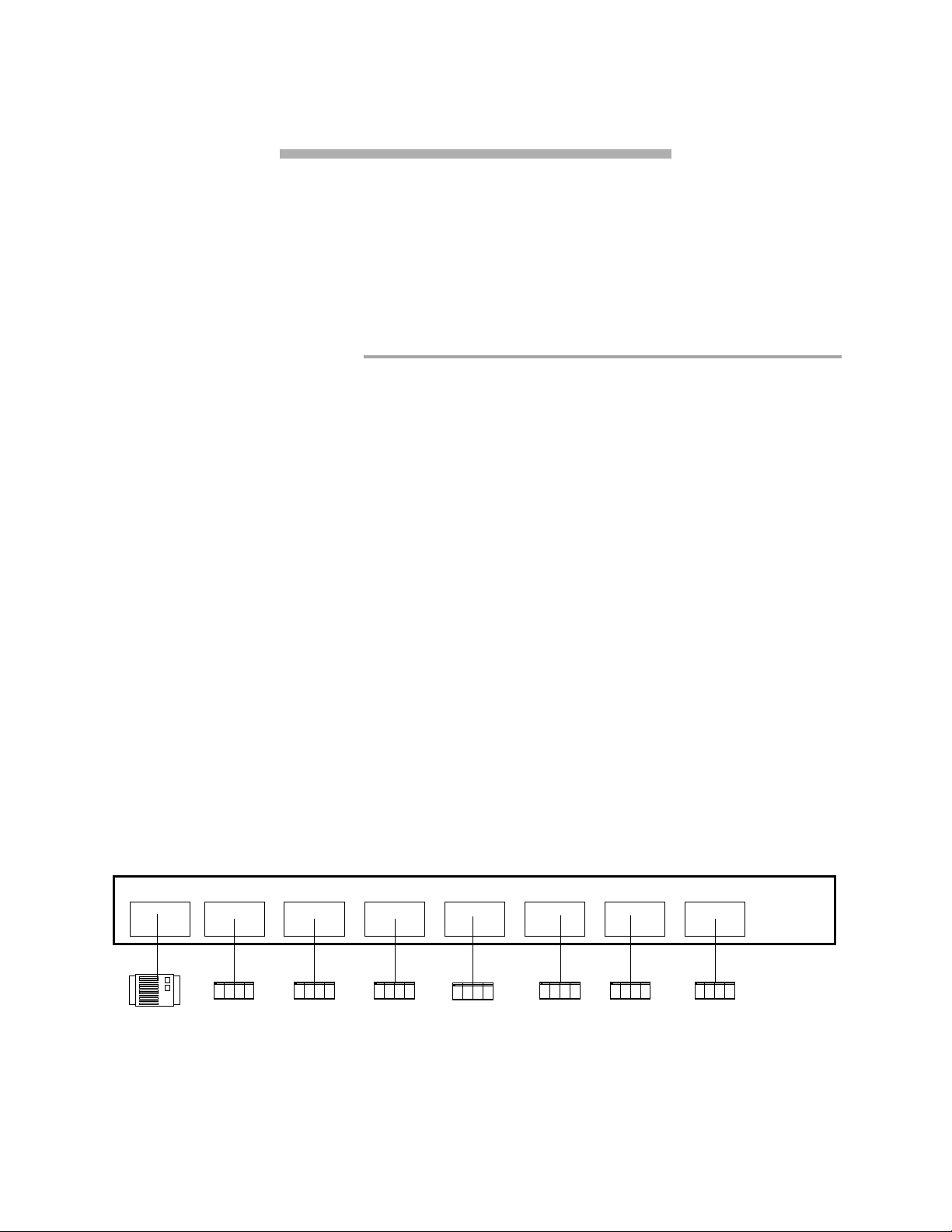
Exhibit 2-1 Single zone configuration (Zone 1), an eight-port hub configuration. Ports 2, 3, 4, 5, 6, 7 and 8 may
access port 1, but only one at a time, under control of the
Port 1 Port 2 Port 3 Port 4 Port 5 Port 6 Port 7 Port 8
Disk array
ATTO FibreCenter 3400
3
Ins
tallation and Operation Manual
Setup
Zone 1
Host
and
Switch
Host
commands.
Host
HostHost Host Host
Page 9
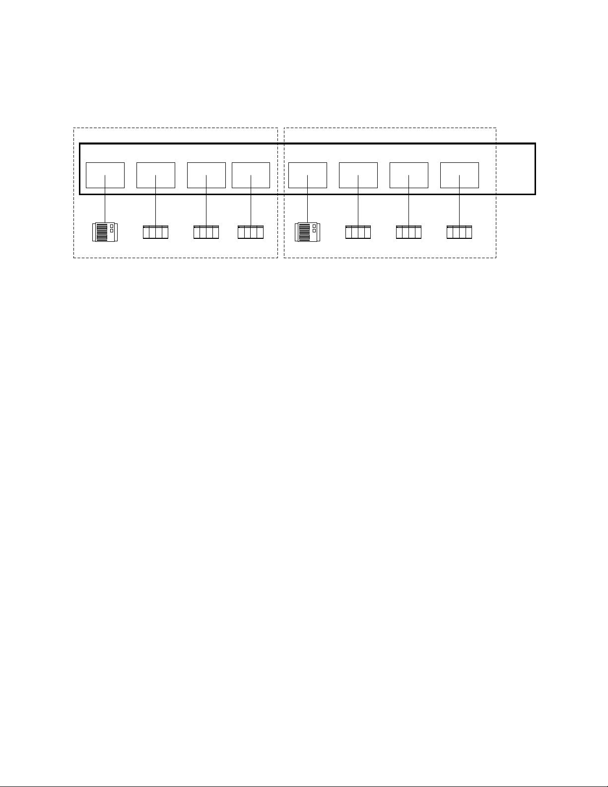
Exhibit 2-2 Dual-zone configuration (Zone 2 and Zone 3). Each zone is independent of the other, and so may be
configured to run at different or the same speed: 1 Gigabit or 2 Gigabit. Ports 2, 3 and 4 may access port 1, but only
and
Setup
Switch
one at a time, under co ntr ol of the Command Line Interf ace
port 5, but only one at a time under control of the
Port 1 Port 2 Port 3 Port 4 Port 5 Port 6 Port 7 Port 8
Setup
Switch
and
commands.
commands. P o rts 6, 7 and 8 may access
Zone 3Zone 2
Disk array
Host
Disk array
Host HostHost Host Host
Secure Data Path Applicationv 4
Page 10

3 ATTO FibreCenter 3400 characteristics
ATT O Fibr eCenter 3400 is a 2-Gigabit Fibre Channel hub configured with eight (8) Fibr e Channel ports
and an Ethernet management port. The FibreCenter 3400 is designed to integrate industry leading
performance and Storage Area Network (SAN) capabilities into mid-range applications by providing a
high-speed, central connection point for Fibre Channel connections.
The FibreCenter 3400 Fibre Channel rack system
design provides maximum dependable
performance for high availability systems through
a hot-swap pa b le , du al power module.
The FibreCenter 3400 module is housed in one
module bay of a dual module, 1U high, industry
standard rack enclosure complete with mounting
brackets. Using two modules in a rack provides a
maximum port density of 16 SFP ports and
redundant power and cooling in a full width 1U
rack.
The unit may be configured as one 8-port hub
(Zone 1) or two 4-port hubs (Zones 2 and 3).
When configured as Zones 2 and 3, the
FibreCenter allows each 4-port zone to run at
different speeds (1Gb or 2Gb). Configuration is
managed through a 10BaseT Ethernet port.
Specifications
❈
Eight 2-Gigabit Fibre Channel ports with
Small Formfactor Pluggable (SFP) interface
❈
400 MB/sec. maximum throughput in full
duplex mode per zone
❈
Auto negotiation between 2-Gigabit and 1-
Gigabit modes
❈
Port management interface for “on-the-fly”
configuration
❈
Ethernet configuration, management and
monitoring
❈
Modular design for maximum data reliability,
availability and serviceability.
❈
Support for Fibre Channel Class 2, Class 3
and Intermix specifications
❈
Support for full-d up lex data transfers
❈
Full Fibre Channel support for FC-P2, PLDA
and public loop login
❈
32 MB of SDRAM memory for code
execution and Ethernet packets.
❈
4 MB of flash memory, field upgradable
through Ethernet, for code and parameter
storage.
Local and network management
❈
Command Line Interface provides local and
remote management and diagnostic support
using Telnet over Ethernet
❈
Field upgradeable firmware using FTP
through the Ethernet port
Features
❈
Digital retiming circuits eliminate jitter
transfer to downstream devices.
❈
Lockable port status
Disabled = Port is disconnected from FC
network.
Enabled = Port is connected to F C network
subject to automatic bypass criteria.
❈
Automatic bypass may be disabled to allow
link to always remain connected.
❈
Link transmitter may be optionally disabled
when port is disabled.
Reduced power consumption.
No external monitoring of FC activ ity.
❈
All settings are persistent.
ATTO FibreCenter 3400
5
Ins
tallation and Operation Manual
Page 11

Exhibit 3-1 Front view of the FibreCenter 3400
Exhibit 3-2 Module view of the FibreCenter 3400
Secure Data Path Applicationv 6
Page 12

4 Setting up the FC Rack System
The ATTO FC Rack System is a configurable 19-inch rack system with two bays designed to house the
ATTO FibreCenter 3400. The 1U rackmount enclosure provides the flexibility to integrate the
ATTO FibreCenter in pairs.
The following items are included with the ATTO
FC Rack System:
❈
Up to two (2) ATTO FibreCenter modules
❈
One (1) or tw o (2 ) power modules.
❈
One (1) or two (2) independent cooling fans
❈
One (1) or two (2) AC shielded power
cord(s).
❈
Two (2) Rackmount “L” brackets and (4)
screws for mounting the unit into the rack.
The main enclosure of the A TTO F C Rack System
houses all the FibreCenter modules and power
modules: two bays for FibreCenter and two bays
for power modules.
Physical dimensions
Width:
Depth:
Height:
17.4 inches (441.6 mm)
17 inches (431 .5 mm)
1.72 inches (43.7 mm)
Operating en vir onm ent
Operating temperature:
Humidity:
0-90% non-condensing
0-40° Celsius
Mounting
You can install the ATTO FC Rack System with
ATTO product modules facing the front or the
back using the "L"-brackets and mounting holes
provided on either end. The mounting holes on the
"L"-bracket fit a standard 19-inch rack, using a
centered 1.25-inch (31.7 mm) hole pattern.
Air flow and cooling
The FC Rack System cooling fans are contained
within the power module. Each power module
contains two 8-CFM fans and provides a total of
16 CFM of airflow. A system that has two power
modules installed will have a total of 32 CFM of
airflow. Air enters through the sides of the
enclosure and is exhausted out the power
modules. Ambient air near the inlets should not
exceed 40° C.
W ARNING
main enclosure. Blocking the vents may cause
overheating and could damage the product.
Do not block the vents on either side of the
Internal power distribution
The ATTO FC Rack System provides a redundant
power scheme with two hot swappable power
supply modules. Each power supply module feeds
12V to the backplane. From there the power is
distributed to the FibreCenter 3400 modules and
the fans.
A failure of one power supply will not affect the
functionality of the modules or the cooling system
since the second supply will continue to supply
power to the backplane. In a redundant power
supply installation, one supply can be removed
and replaced without affecting the rest of the
system in any way.
The product module will detect power supply
failures, voltage regulation and failover.
NOTE: Power modules will load balance
when two are present in the ATTO FC Rack
System
The po wer module is a hot sw a p pab le un it th at
contains enough power to supply two ATTO
product modules and four cooling fans. Each is
designed to slide into the ATTO FC Rack System
enclosure in either of the two bays on the end of
the rack enclosure that is closer to the backplane
and farther away from the cooling vents in the
sides of the rack enclosure.
Input voltage:
110/230V AC, with an operating
input range of 90-132V AC or 175-264V ac, 4763Hz, single phase. The AC input range selection
is automatic. No manual jumper or switch over is
required.
ATTO FibreCenter 3400
7
Ins
tallation and Operation Manual
Page 13

Output voltage:
+12 Volts @ 5 Amps (60 watts)
continuous, 5.8 amps (70 watts) peak.
Power draw:
The maximum power draw is 2
Amps @ 110 Volts for the entire ATTO FC Rack
System. When the ATTO FC Rack System has
two power modules, the entire unit will draw 2
Amps @ 110 Volts.
LED indicator
The green LED indicator on the
power module will light when the module is
correctly installed and the switch is turned on
showing that power is being drawn from this
module and is available on the backplane. The
LED will not be illuminated if the power module
is not turned on.
W ARNING
the power switch if the power module is not installed.
IEC Power Receptacle and Switch
Do not plug the A C po wer cord in and turn on
One standard
IEC320 power receptacle and switch provides
easy adaptability to different voltage standards
throughout the world.
Installing a power module:
1 Make sure the power switch on the rear of
the power module is in the
the power cord is disconnected.
Exhibit 4-1 Rack System power module
position and
off
2 Slide the power module into the rack
enclosure until you feel it make contact with
the backplane connector. The face of the
power module should be flush against the
rack enclosure edges.
3 Secure the power module by tightening the
two thumb screws (hand tight).
4 Connect the AC power cord to the power
module and plug it into an appropriate
receptacle.
5 Turn the power switch on the powe r module
to the on position. Verify that the green LED
is illuminated.
Removing a power module:
1 The power switch on the rear of the power
module must be in the
sure the power LED is NOT illuminated.
2 Disconnect the power cord from the power
module as well as the AC power source.
3 Loosen the two thumb screw s on the face of
the power module.
4 Carefully slide the power module out of the
rack enclosure.
position. Make
off
Exhibit 4-2 Cooling airflow patterns
Secure Data Path App l icati o nv 8
Page 14

5 Setting up the ATTO FibreCenter
The ATTO FibreCenter 3400 fits into a standard rack mount module enclosure. While configuration
changes can be made “on the fly,” data transmission will be interrupted. To make changes without
impacting data, make changes before activating data transmission.
Installing the FibreCenter
1 Slide the hub module horizontally into the
rack enclosure until you feel it make contact
with the backplane connector. The face of
the hub module should be flush against the
rack enclosure’s edge.
2 Secure the hub module by tightening the
two thumbscrew s (hand tight).
3 Apply power to the rack enclosure.
•The ATTO FibreCenter takes about 40
seconds to begin operation after po wer -up
or execution of the
ports are disabled during this 40 seconds.
•When the FibreCenter begins operation, it
will use its default configuration or the last
mapping designated by the
Switch
•The power LEDs will illuminate
immediately.
•All FibreCenter port LEDs will blink one at
a time, from left to right, then all will blink
twice to indicate they are functional.
•The FibreCenter is now active.
4 Connect to the management port via a
standard RJ45 Ethernet cable. It may take
up to 40 seconds for the hub to initiate the
Ethernet connection.
5 Connect Fibre Channel devices to the ATTO
FibreCenter using SFPs and standard
cables manufactured for Fibre Channel use.
commands.
command. All
Reset
Setup
and
•Cable limitations are listed in the chart on
the next page.
•The Online LED illuminates for each port
with a connected cable if the connected
device is powered up and online.
6 Connect a host computer to the
FibreCenter. The default IP address of the
hub is 192.168.1.1. Unless your network is
running under 192.168.1.X, you will need to
use a crossover Ethernet cable to connect.
7 Change the IP address of the host computer
to 192.168.1.X (where X does not equal 1).
8 Launch Hyperterminal.
9 From the menu bar at the top, select
New Connection
10 Enter a name for the connection.
11 Select
method.
12 Enter the IP address of the FibreCenter.
13 Enter
login.
14 When prompted for a password, type in y our
password. Default is
15 Y ou should no w be connected. Type
a list of commands. Enter the CLI
commands required to set up your s ystem if
different from pre viously set configurations
or defaults.
TCP/IP (Winsock)
zonedhub
when prompted for the
as the connection
zonedhub
.
File -
help
for
To change the password
1 To change the password you must be
logged in as
2 The default password for root is
should be changed as soon as possible.
3 If you are changing t he root passwor d, at the
prompt, type
bash#
ATTO FibreCenter 3400
9
root.
passwd root.
Ins
tallation and Operation Manual
and
root
If you are
changing the zonedhub password, type
passwd zonedhub
4 You will be prompted for a new password.
5 You will be prompted to retype the new
password.
at the bash prompt
.
Change in password is effective immediately.
Page 15

Connecting Fibre Chan nel ports
The Fibre Channel ports connect into an
Arbitrated Loop.
When devices connected to the FibreCenter 3400
are powered up, each NL_Port must sign in with
the other ports on the loop. Each port first
attempts to find an FL_Port within the loop.
When it does, it kno ws it is a part of a p ublic loop
connected to a fabric. If it does not, it knows it is
a part of a private loop consisting of other
NL_Ports on ly.
Arbitrated loops can have up to 126 active
NL_Ports but only one active FL_Port because the
FL_Port is considered the master. You may not
configure two switch ports (same switch or
different switches) because that would create two
FL_Ports.
The FibreCenter can connect direct to a fabric
switch, but the switch port must be configured as
an FL_Port (Loop Mode).
When connecting to a switch, make sure that only
one port of the FibreCenter 3400, or multiple hubs
daisy chained together, are connected to the
switch.
Y ou may not connect ports from multiple switches
to the same loop FibreCenter 3400.
Cabling
Fibre Channel technology offers a variety of
cabling options including standard copper,
equalized copper, multimode fiber optic, and
single mode fiber optic.
The FibreCenter 3400 uses a Small Formfactor
Pluggable (SFP) Fibre Channel interface.
The type of cable to use varies depending upon
the application, environment and distance. The
following table illustrates the different cable
options available.
Make sure all cables are anchored securely at both
ends with the proper connectors.
Cable length Cable type Cable size Connector
Up to 175 meters multimode fiber optic 62.5 micron LC
Up to 500 meters multimode fiber optic 50 micron LC
Up to 13 meters unequalized copper HSSDC-2
Removing the FibreCenter
1 Disconnect all cables from the face of the
hub module.
2 Loosen the two thumbscrews on the face of
the hub module.
3 Carefully slide the hub module out of the
rack
Secure Data Path Applicationv 10
Page 16

6 Configuring the ATTO FibreCenter
The A TT O FibreCenter 34 00 ma y be con f ig ured as one 8-port hub (Zone 1) or two 4- port hubs ( Zone 2
and Zone 3). Each Fibre Channel bus in the two-zone configuration can run at different speeds (1Gb or
2Gb). The zones may be configured as either a one or two A-B style switch in a FC-AL loop.
Config u r a tio n is ma naged through a 10 /100 Ba seT E th erne t port .
The software necessary to drive the FibreCenter
3400 consists of two segments: the switching
logic and the command-processing logic.
The switching logic sets up hardware
configurations. The command-processing logic
allows you to change parameters on the
FibreCenter 3400 and view responses and other
information about the hub and its performance via
a Telnet server program and command line
interface commands (see Chapter 7.3)
The ATTO FibreCenter 3400 may be configured
as one 8-port hub (Zone 1) or two 4-port hubs
(Zone 2 and Zone 3) using the Setup and Switch
CLI commands. Each Fibre Channel bus in the
two-zone configuration can run at different speeds
(1Gb or 2Gb). The zones may be configured as
either a one or two A-B style switch in a FC-AL
loop. A zone is defined by the following
parameters:
❈
A zone contains only adjacent ports.
❈
Except for the Get Switch command return,
Ports are labeled P1 through P8: all
connections are assumed to be between port
P1 and P2 | P3 | P4 | P5 | P6 | P7 | P8 in zone
1, between port P1 and P2 | P3 | P4 in zone 2
and between port P5 and P6 | P7 | P8 in zone
3. In the Get Switch command return, ports
are labe le d w it h le t te r s .
❈
Zone 2 and Zone 3 do not overlap.
❈
Within a zone, all ports are disabled except
the lo west-numbe red port (cou nting from th e
left) and the single other port to which it is
switched.
Data transfer when setting up zones
Y ou must temporarily stop data transfer to the hub
when you execute the Setup and Switch
commands during setup of the A TTO FibreCenter .
Only the initiators can stop data transfer; the
FibreCenter cannot stop data transfers.
❈
If you are changing the FibreCenter 3400
from a single-zone configuration to a dualzoned configuration, you must temporarily
stop all data transfers from the host to the
FibreCenter.
❈
If you are changing zone 2 setup in a dualzoned configuration, but not changing zone
3, you must temporarily stop all data
transfers from the host in zone 2 but data
transfer may continue in zone 3.
❈
If you are changing from a dual-zoned
configuration to a single-zoned
configuration, you must temporarily stop all
data from the host to the FibreCenter.
FibreCenter behavior on
reset
power-up
or
The ATTO FibreCenter takes about 40 seconds to
begin operation after power-up or execution of the
Reset command. All ports are disabled during this
40 seconds. When the FibreCenter begins
operation, it will use its default configuration or
the last mapping designated by the Setup and
Switch commands.
Zone 1
The FibreCenter 3400 may be configured into one
zone in which all eight ports are available. Up to
seven de vices may access the eighth port, one at a
time.
Zone 2 and Zone 3
The FibreCenter 3400 may be configured into two
separate zones. In each zone, up to three devices
may access the fourth port in that zone, one at a
time. Devices in one zone may not access ports in
the other zone.
ATTO FibreCenter 3400
11
Ins
tallation and Operation Manual
Page 17

FibreCenter 3400 Switching Patterns
A-B switch model
Hub ports
Zone P1 P2 P3 P4 P5 P6 P7 P8
1
✓✓✓✓✓
✓
✓✓
1
✓✓✓✓✓
1
✓✓✓✓✓
1
✓✓✓✓✓
1
✓✓✓✓✓
1
✓✓✓✓✓
1
✓✓✓✓✓
2
✓✓✓✓✓
2
✓✓✓✓✓
2
✓✓✓✓✓
✓
✓✓
✓
✓✓
✓
✓✓
✓
✓✓
✓
✓✓
✓
✓✓
✓
✓✓
✓
✓✓
✓
✓✓
Inv a lid Switching Patterns
Zone P1 P2 P3 P4 P5 P6 P7 P8 Reason:
any
✓✓✓
2
✓✓
3
✓✓
must be 1-1 map
P8 not in zone 2
P4 not in zone 3
3
3
3
✓✓✓✓✓
✓
✓✓
✓✓✓✓✓
✓✓✓✓✓
✓
✓✓
✓
✓✓
Exhibit 6-1 Single zone configuration (Zone 1), an eight-port hub configuration. Ports 2, 3, 4, 5, 6, 7 and 8 may
access port 1, but only one at a time, under control of the commands
Zone 1
Port 1 Port 2 Port 3 Port 4 Port 5 Port 6 Port 7 Port 8
Disk array
Setup
HostHost
Exhibit 6-2 Dual-zone configuration (Zone 2 and Zone 3) as designated by the
and
Switch
Host
Setup
.
and
HostHost Host Host
Switch
commands. Each
zone is independent of the other, and so may be configured to run at different or the same speeds: 1 Gigabit or 2
Gigabit. Ports 2, 3 and 4 may access port 1, but only one at a time. Ports 6, 7 and 8 may access port 5, b ut onl y one at
a time.
Zone 3Zone 2
Port 1 Port 2 Port 3 Port 4 Port 5 Port 6 Port 7 Port 8
Disk array
Disk array
Host
Host HostHostHostHost
Secure Data Path Applicationv 12
Page 18

7 Command Line Interface use and guidance
You will be able to perform all configuration via the Telnet interface through the Ethernet port using
Command Line Interface (CLI) commands.
To configure the ATTO FibreCenter you will
access the Command Line Interface (CLI), a set of
ASCII commands, through a Telnet session.
Except for the Get Switch command return, ports
are labeled 1 through 8: all connections are
assumed to be between port 1 and 2 | 3 | 4 | 5 | 6 |
7 | 8 in zone 1, between port 1 and 2 | 3 | 4 in zone
2 and between port 5 and 6 | 7 | 8 in zone 3. In the
Get Switch command return, ports are labeled
with letters.
Zone 1
Port 1 Port 2 Port 3 Port 4 Port 5 Port 6 Port 7 Port 8
BEGFDCA
Zone 2 Zone 3
Port 1 Port 2 Port 3 Port 4 Port 5 Port 6 Port 7 Port 8
BCA
BCA
CLI command con v entions
❈
CLI commands are case insensitive: you may
type all upper or all lower case or a mixture.
Upper and lower case in this manual and the
help screen are for clarification only.
❈
Responses to commands are specified in the
Results field for each command, followed by
the Telnet prompt $ .
❈
Symbols, typefaces and abbreviations used to
indicate functions and elements of the
command line interface used in this manual
include those found in Exhibit 7-3.
❈
The settings re sident in the FibreCenter 34 00
will be preserved over a power-off, power -on
cycle and restored automatically on poweron.
ATTO FibreCenter 3400
13
Ins
tallation and Operation Manual
Page 19

Exhibit 7-3 Command conventions. Do not type symbols when entering commands.
Symbol Indicates
[ ] Required entry
• Space character (ASCII 32 decimal)
< > Optional entry
| pick one of
… Ellipses, repetition of preceding item
\n end of line
– a range (6 – 9 = 6, 7, 8, 9)
Boldface w ords must be typed as they appear
Italicized words Parameters which must be replaced by whatever they represent
RACK 000 or 000 required parameters
LL Hub zone [ 01 | 02 | 03 ]
C Channel or port number
such as [ 2 | 3 | 4 | 5 | 6 | 7 | 8 ] in single-zone (Zone 1) configuration
Exhibit 7-4 A typical command/response sequence during a Telnet session.
Telnet session
screen Explanation
setup•000:0120 Prepares to connect port 1 to port 2 .in zone 1
OK
$
switch
Valid input, accepted
Telnet prompt: ready for next command. Type the next comm and
immediately after the prompt ($ switch)
Implements changes to the hardware configuration, connecting port 1 to
OK
$
port 2 in zone 1
Connection complete
Telnet prompt: ready for next command
Secure Data Path Applicationv 14
Page 20

7.1 Ethernet and Telnet configuration commands
Configure the AT TO FibreCenter 3400 using a Telnet session over the Ethernet port. The commands in
this section configure or provide information about the Ethernet port and the Telnet session.
Default Router
Sets a new default router address for the Telnet server. Set the default r o uter within the subnet as defined by the sub n e t mask and IP Address.
Limit: 0-255
Action:
set•RACK •000•Default•Router•[n.n.n.n]
reset•rack•000
or power cycle
Echo
Sets the Telnet command echo mode.
Limits: [on|off]
Action:
set•RACK •000•Echo•[on|off]
reset•rack•000
or power cycle
Factory Defaults
The Telnet parameters are set to their factory default values.
Action:
set•RACK •000•Factory•Defaults
reset•rack•000 or
power cycle
Idle Timeout
Sets time period in seconds after which, if there is no action on the Telnet port, the Telnet session is shut down.
Action:
set•RACK •000•Idle•Timeout•[n]
reset•rack•000 or
power cycle
IP Address
Sets a new IP address which will be used after next reset.
Limit: 0-255 Default: 192.168.1.1
Action:
set•RACK •000•IP•address•[n.n.n.n]
reset•rack•000 or
power cycle
Security Traps
Sets the Telnet security level
Action:
set•Security•Traps•[n]
reset•rack•000
or power cycle
Subnet Mask
Sets a new subnet mask which will be used after next r e set.
Limit: 0-255 Default: 255.255.255.0
Action:
set•RACK •000•Subnet•Mask•[n.n.n.n]
reset•rack•000
or power cycle
Default: 0.0.0.0
Information:
Information:
Information: no ne
get•RACK •000•Default•Router
get•RACK •0 00 •Ec h o
Default: 60 minutes
Information:
Information:
get•RACK •000•Idle•Timeout•[n]
get•RACK •000• IP•Address
Default: 3
Information:
Information:
get•RACK •000•Security•Traps
get•RACK •000•Subnet•Mask
Telnet
Ends the current Telnet session and opens another
Action:
Telnet
Information: no ne
T elnet Status
Returns the Telnet status. The format will be determined in the future.
ATTO FibreCenter 3400
15
Ins
tallation and Operation Manual
Page 21

7.2 Diagnostic commands
The commands in this section only provide information about the ATTO FibreCenter 3400. Access this
information using these command line interface commands in a Telnet session over the Ethernet port.
Status
Displays the status of the power supplies and the cooling fans.
Limits:
PP = power suppl y status; OK = oper ating, NG=inoperable, NI = missing
FF = cooling fan status: OK = operating
K = L
Action: none Information:
Return syntax: Status•000•PS1:PP•FAN1:FF•PS2:
PP•FAN2:FF•KEY:K
Return exam ple:
Status•000•PS1:OK•FAN1:OK•PS2:OK•FAN2:OK•KEY:L
T elnet Status
Returns the Telnet status.
Limits: Status may be narrowed to [1] Telnet session information [2] TCP statistics or [3] Telnet auditing information
Action: none Information:
Version
Displays the firmware version of the rack. The FibreCenter 3400 has two processors. Returns reflect status of the ARM firmware and the Xilinx
firmware.
Limits: n = ARM firmware version; x = Xilinx firmware version
Action: none Information:
Return: n.nn- xxx
get•Status•000
get•RACK •000•Telnet•Status• [1|2|3]
get•RACK •000•Version
Secure Data Path Applicationv 16
Page 22

7.3 Configuration commands
Configure the A TTO F ibreCenter 3400 using a T elnet session over the Ethernet port. The commands in this section
configure or provide information about the ATTO FibreCenter 3400.
Flush, Setup
closely related.
Flush
Undoes all previous
Actions:
Flush•000
Rate
Sets (fixes) t h e data rate for each zone in the FibreCen te r 3400. The rate will ordinarily be set through auto negotiation bu t this command has
the power to fix the ra te at either 1G b or 2Gb , regardless of auto negotiation. When the
zone and does not mean autonegoti ate.
Limits: [0|1|2] for auto negotiate, 1Gb or 2 Gb in zones 01, 02 or 03.
Actions:
Example: set•RACK•000•Rate• ••1•2
(sets zone 02 in 1 Gb, zone 03 as 2 Gb)
set•RACK•000•Rate•[0|1|2]•[0|1|2]•[0|1|2]
Reset
Performs a “warm boot” including POST and refreshes all configuration setting s. All software in Flash memory is reloaded into RAM.
Actions:
Reset •RACK•000 Information: none
Setup
Prepares the FibreCenter 3400 for the requested config uration and saves all configuration i nformation internally wi thout making hardware
changes. Hardware changes require a
Syntax: setup•000:[LL][C]0
Actions:
Setup•000:02 [2|3|4]0
Setup•000:03 [6|7|8]0
See Exhibit7.3-1 for examples of returns
Setup•000:01 [2|3|4|5|6| 7|8]0
Switch
Commits all previous
configured zone, waits for the amount time designed in
command. The
Actions:
get switch
Switch•000
Switch Delay
Determines the amount of time before the
Limits: 0 to 2000000 µsec (0-2 seconds) Default: 20000 µsec
Actions:
set Switch•delay [0-2000000]
commands since the most recent
Setup
command.
Switch
commands since the most recent
Setup
Switch Delay
command returns the ports as alphabetic characters because the hub is acting as an A-B switch.
command takes effect in microseconds (µsec).
Switch
or
Flush
Information:
Information:
Return:
Information: none
Flush
Information:
See Exhibit 7.3-1 for examples of returns
Information:
command
Switch
none
command r eturns 0, the 0 i s a placehold er for a
get rate
get•RACK•000•Rate
RACK•000•Rate •1•0•0
or
command. The
Switch
command (default is 20000 microseconds), then implements the
get•Switch•000
get•Switch•Delay
Switch
(1Gb in zone 01)
command f ir st tur ns off all ports within the
and
Switch
commands are all
Setup
ATTO FibreCenter 3400
17
Zone 1
Port 1 Port 2 Port 3 Port 4 Port 5 Port 6 Port 7 Port 8
BEGFDCA
Zone 2 Zone 3
Port 1 Port 2 Port 3 Port 4 Port 5 Port 6 Port 7 Port 8
BCA
Ins
tallation and Operation Manual
BCA
Page 23

Exhibit 7.3-1 Command line interface
FibreCenter 3400 Switching Patterns
setup
commands and
A-B switch model
get switch
returns for Zones 1, 2 and 3
Hub ports
Zone P1 P2AP3BP4 CP5 DP6EP7FP8
1
✓✓
1
✓✓
1
✓✓
1
✓✓
1
✓✓
1
✓✓
1
✓✓
Zone A B C A B C
2
✓✓
2
✓✓
2
✓✓
3
✓✓
creates configuration;
G
implement with switch
command
Setup
setup • 000 : 0120 switch
setup • 000 : 0130 switch
setup • 000 : 0140 switch
setup • 000 : 0150 switch
setup • 000 : 0160 switch
setup • 000 : 0170 switch
setup • 000 : 0180 switch
setup • 000 : 0220 switch
setup • 000 : 0230 switch
setup • 000 : 0240 switch
setup • 000 : 0360 switch
Get Switch
return
after setup & switch commands
• 000 • • A •
• 000 • • B •
• 000 • • C •
• 000 • • D •
• 000 • • E •
• 000 • • F •
• 000 • • G •
• 000 • • • • • • A •
• 000 • • • • • • B •
• 000 • • • • • • C •
• 000 • • • • • • • • • • A •
3
3
✓✓
✓✓
setup • 000 : 0370 switch
setup • 000 : 0380 switch
• 000 • • • • • • • • • • B •
• 000 • • • • • • • • • • C •
Secure Data Path Applicationv 18
Page 24

8 Updating firmware
The Linux Kernel and the Flash File System may be updated by accessing the FibreCenter 3400 through
an Ethernet network.
Linux Kernel Update
1 Attach the FibreCenter 3400 to an Ethernet
network.
2 Configure the FibreCenter for Ethernet
access.
3 Start up a Telnet session on the host to the
IP address of the FibreCenter 3400 and login
as
4 At the
password, type
and hit
5 Wait for the process to complete. Once
completed, the FibreCenter 3400 system is
ready to accept a new Linux kernel.
6 On the host, name the new kernel file
mtdchar0
7 FTP the file
on the FibreCenter 3400.
8 When the FTP process is complete, cycle
the power on the FibreCenter 3400 and login
.
root
prompt, after entering your
bash#
flash_erase /dev/mtdchar1
.
Enter
if this is not its name already.
mtdchar0
from the host to
/dev/
in the usual manner
prompt, type
reboot
at the
OR
and hit
Enter
bash#
.
Flash File System (FFS) Update
1 Attach the FibreCenter 3400 to an Ethernet
network.
2 Configure the FibreCenter for Ethernet
access.
3 Close all previous open sessions
(zonedhub or root logins).
4 FTP the new application files from the host
to
/mnt/flash/
5 When the FTP process is complete, login as
root.
6 Type the foll owing at the
7 Type
cd /mnt/flash
chmod +x zonedhub sleep setmac xloader
chmod +s zonedhub
chmod 666 *.xml
reboot
prompt.
in the FibreCenter 3400.
prompt
bash#
and hit
Enter
at the
bash#
ATTO FibreCenter 3400
19
Ins
tallation and Operation Manual
Page 25

9 Troubleshooting
The fault LED indicates that a signal is being received, but the signal contains enough faults to make
the port fail and go into bypass mode.
Port LEDs on the ATTO FibreCenter are
generally lighted if the port is enabled through the
Setup CLI command and an active device is
connected to the port. However , if you want to test
Forcemode while in the command line interface.
If the FibreCenter is not in force mode, however,
the port LEDs will behave as illustrated in the
table below.
your configurations without having active devices
attached to the ports, enter the command Switch-
LED If LED is illuminated If LED is not illuminated
OnLine Port is on-line and functioning properly No cable connected
Cable connected, but no device or host connected to cable
Cable connected between hub and connected device or
host, but the device is powered off
Fault See information below ATTO FibreCenter port is operating pr operly
Power A ATTO FibreCenter is receiving power
through power supply A
Power B ATTO FibreCenter is receiving power
through power supply B
Power supply A is not installed or turned on
A power suppl y is active , but the FibreCenter i s not receiving
power through power supply A
Power supply B is not installed or turned on
A power suppl y is active , but the FibreCenter i s not receiving
power through power supply B
Fault LED Condition
ON Port has been taken off-line, because it is not receiving proper signals due to the following:
➔
➔
➔
➔
➔
Port is receiving bad / discontinuous signals
Bad cables
Device connected to the port is powered on, but failed
Cable may be too long / signal has deteriorated
SFP fault – an i nternal f ault within the SFP connected to the port requires replacement.
Secure Data Path Applicationv 20
Page 26

Index: Command Line Interface
A summary of the Command Line Interface commands, their defaults, an example of how they might be
used, and where you can find the specifics of the command. Commands which have no default values
associated with them have a blank entry in that column of the table.
Command Default Example Page
Default Router 0.0.0.0 set•RACK •000•Default•Router•0.1.0.1 15
Echo on set•RACK •000•echo•off 15
Factory Defaults set•RACK •000•factory
Flush flush•000 17
Idle Timeout 60 minutes set•RACK •000•idl e•timeout•30 15
IP Address 192.168.1.1 set•RACK •000•ip
Rate set•RACK •000•rate•1•1•2 17
Reset reset•rack•000 17
Security Traps 3 set•RACK •000•security
Setup setup•000:0120 17
Status get•status•000 16
Subnet Mask 255.255.255.0 set•RACK •000 •subnet
Switch get•switch•000 17
Switch Delay 20000 µsec. set•switch•delay•20005 17
Telnet Telnet 15
Telnet Status get•RACK •000•Telnet•status 15
Version get•RACK •000•vers i on 16
defaults 15
•
address• 10.0 .0.1 15
•
traps•2 15
•
mask• 255.255.0.0 15
•
ATTO FibreCenter 3400
i
Ins
tallation and Operation Ma nual
Page 27

Appendix A Standards and compliances
The ATTO Technology FibreCenter 3400 described in this manual generates and uses radio frequency
energy. If this equipment is not used in strict accordance with the manufacturer's instruction, it can and
may cause interference with radio and television reception. See the Technical Specification sheet for a
full list of certifications.
UL 1950 3rd Edition
FCC Standards: Radio and Television Interference
W ARNING
energy and , if not installed a nd used in accordan ce with the instruction manual, ma y cause
interfe rence to radio communicat ions. It has been tested and found to comply with the limits
for a Class A computing device pursuant to Subpart J of Part 15 of FCC rules, which are designed to provide a
reasonable protection against such interference when operating in a commercial environment. Operation of this
FibreCenter in a residential area is likely to cause interference, in which case the user, at his own expense, will be
required to take whatever measures may be required to correct the interference.
If this FibreCenter does cause interference to radio and television reception, which can be determined
by turning the equipment off and on, try to correct the interference by one or more of the following
measures:
The ATTO FibreCenter 3400 gen erates, us es, and can r adiate radio fre quency
❈
Move the receiving antenna.
❈
Relocate the FibreCenter with respect to the receiver, or move the bridge away from the receiver.
❈
Plug the computer into a different outlet so the computer and receiver are on different branch
circuits.
❈
If necessary, consult an ATTO authorized dealer, ATTO T echnical Support Staff, or an experienced
radio/television technician for additional suggestions.
The booklet How to Identify and Resolve Radio/TV Interference Problems prepared by the Federal
Communications Commission is available from the US Government printing office, Washington, DC.
Canadian Standards
This Class A digital apparatus complies with Canadian ICES-003.
Cet appareil numérique de la classe A est conforme à la norme NMB-003 du Canada.
European Stan dards: Declaration of Conf or m ity
This device has been tested in the basic operating configuration and found to be compliant
with the following European Union standards:
Application of Council Directive: 89/336/EEC
Standard(s) to which conformity is declared: EN55022, EN50082-1
This Declaration will only be valid when this product is used in conjunction with other CE approved
devices and when the entire system is tested to the applicable CE standards and found to be compliant
Secure Data Path Applicationv iii
Page 28

Appendix B Contact ATTO Technology, Inc.
Customer service, sales information and technical support are available by phone Monday through Friday,
Eastern Standard Time 8:00 a.m. to 8:00 p.m., or by fax and web site 24-hours a day.
ATTO Technology, Inc.
155 CrossPoint Parkway
Amherst, New York 14068
(716) 691-1999 • voice
(716) 691-9353 • fax
http://www.attotech.com
ATTO Technology can also be reached via e-mail at the following addresses:
Sales Support
Technical Support
: sls@attotech.com
: techsupp@attotech.c om
ATTO FibreCenter 3400
iv
Ins
tallation and Operati on M anual
 Loading...