

Page 1
XM000002
Rev. 004
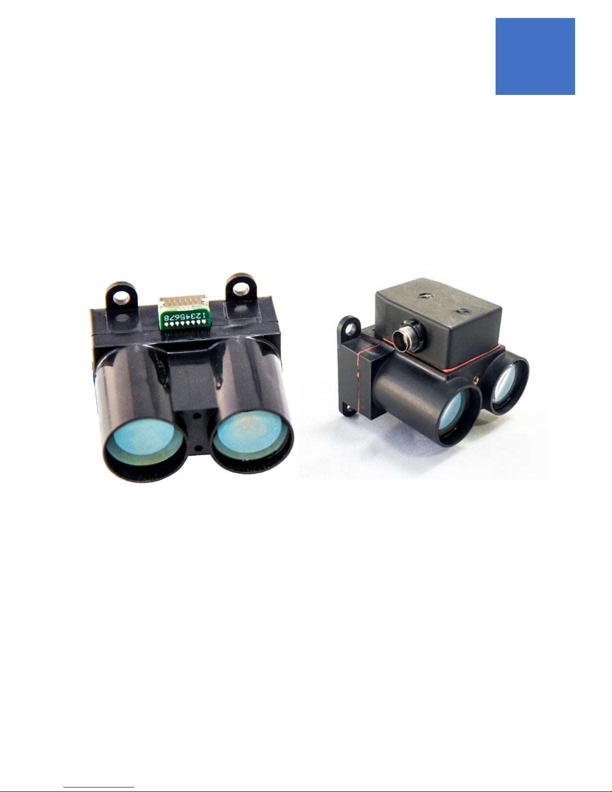
WASP-200 LRF
USER MANUAL - UART (CU1 AND MU1) AND CAN / RS-232 (MC1) VERSIONS
ATTOLLO ENGINEERING
Page 2

WASP-200 LRF
200m Compact Laser Rangefinder
User Manual
XM000002 Rev. 004
1
Contents
INTRODUCTION ................................................................................................................................................................................. 3
PRINCIPLE OF OPERATION ................................................................................................................................................................. 3
PERFORMANCE.................................................................................................................................................................................. 4
POWER .............................................................................................................................................................................................. 4
LASER SAFETY .................................................................................................................................................................................... 5
PHYSICAL ........................................................................................................................................................................................... 5
DIMENSIONS ..................................................................................................................................................................................... 6
PINOUT AND ELECTRICAL INTERFACE ................................................................................................................................................ 8
CU1 ........................................................................................................................................................................................................ 8
MU1 ....................................................................................................................................................................................................... 9
MINIMUM RECOMMENDED CONFIGURATION (CU1 AND MU1) ....................................................................................................................... 10
MC1 ..................................................................................................................................................................................................... 11
COMMUNICATION INTERFACE (CU1 AND MU1) .............................................................................................................................. 13
SERIAL COMMANDS .................................................................................................................................................................................. 14
RANGE ERROR CODES ............................................................................................................................................................................... 20
COMMUNICATION INTERFACE (MC1) .............................................................................................................................................. 21
CAN ...................................................................................................................................................................................................... 21
CAN BUS COMMANDS .............................................................................................................................................................................. 21
CONFIG ............................................................................................................................................................................................ 22
READING .......................................................................................................................................................................................... 22
LASER_MODE & LASER_MODE_2 .................................................................................................................................................... 23
POWER & EXT_POWER .................................................................................................................................................................... 24
SINGLE ............................................................................................................................................................................................. 24
UPDATE_OFFSET ............................................................................................................................................................................. 24
DATE_VERSION ................................................................................................................................................................................ 24
RS-232 COMMANDS ................................................................................................................................................................................ 25
LRF ................................................................................................................................................................................................... 25
USE WITH CLOUD CAP PICCOLO AUTOPILOT .................................................................................................................................................. 25
REVISION HISTORY .......................................................................................................................................................................... 26
Page 3

WASP-200 LRF
200m Compact Laser Rangefinder
User Manual
XM000002 Rev. 004
2
Laser Safety
This device does not require regular maintenance. If the device becomes damaged
or is inoperable, repair or service must be handled by factory authorized technicians
only. Attempting to modify, repair or service the unit on your own will not only result
in voiding the warranty, but is prohibited and could result in direct exposure to laser
radiation and permanent eye damage.
For repair or service, contact Attollo Engineering for more information. Attollo
Engineering is not responsible for injuries caused through the improper use or
operation of this product.
Caution – use of controls or adjustments or performance of procedures other
than those specified herein may result in hazardous radiation exposure.
Attollo Engineering
1260 Avenida Acaso, Suite B
Camarillo, CA 93012
This Laser Product is designated Class 1 during all procedures of operation.
As designed, the laser is safe to look at with the unaided eye, however, it is
advisable to avoid looking directly into the beam when operating the device
and to turn off the unit when not in use.
WARNING
CAUTION
Page 4
WASP-200 LRF
200m Compact Laser Rangefinder
User Manual
XM000002 Rev. 004
3
Introduction
The WASP-200 LRF is an ultra-compact laser rangefinder (LRF) device that is capable of quickly and accurately identifying
the distance to a target ~130 m away assuming 18% or better target reflectance and under full sun illumination conditions;
and even further away with higher reflectance targets and/or lower solar illumination levels. The WASP-200 LRF supports
range update rates of up to 56 ranges-per-second with improved accuracy at lower repetition rates with a variety of
filtering and averaging features. Attollo has three configurations of the WASP-200 LRF:
• CU1 – UART communication interface
• MU1 – Ruggedized, IP67, UART communication interface
• MC1 – Ruggedized, IP67, CAN and RS-232 communication interface using the Cloud Cap Technology
Piccolo autopilot protocol
NOTE: This Laser Product is designated as Class 1 during all aspects of operation.
The WASP-200 LRF has been designed with ease of use and flexibility in mind and therefore supports a +5V-compliant
UART communication interface (CU1 and MU1 models) and requires just power and ground to operate out of the box. The
UART interface can be used to set and save various user parameters and operating modes tailored to your specific
application.
The MC1 is a ruggedized version of the WASP-200 laser rangefinder that is IP67 compliant and is directly compatible with
the Cloud Cap Technology Piccolo autopilot systems using their CAN and RS-232 interfaces. In addition to the Piccolo CAN
interface, the user can access all of the commands and settings of the WASP-200 over the RS-232 interface to set the
various user parameters and operating modes for use while operating with the Piccolo flight controller.
Principle of Operation
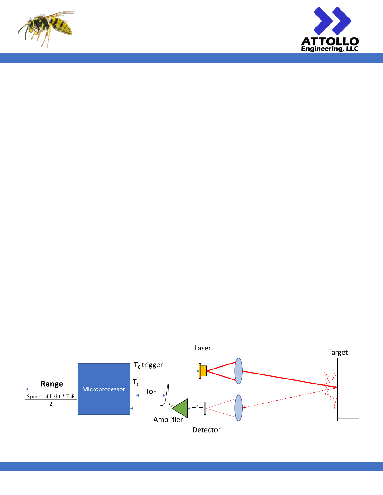
The WASP-200 LRF uses a highly sensitive avalanche photodetector (APD) and short-pulse laser diode. The laser is pulsed
to produce an optical pulse of laser light with a peak power of about 40 Watts. This pulse is collimated with a lens and
transmitted to the target up to 250 meters away (the maximum range capability of the WASP-200 LRF). A small portion of
the light will bounce off the targeted object and end up traveling back to the WASP-200 LRF where it will be collected by
the receiver lens and focused onto a small avalanche photodetector. This light will cause an avalanche of electrons to
flow in the detector thus producing a current pulse which is subsequently amplified and converted into a voltage pulse.
Figure 1 - Conceptual Schematic of the WASP-200 LRF time-of-flight principle of operation
Page 5
WASP-200 LRF
200m Compact Laser Rangefinder
User Manual
XM000002 Rev. 004
4
The WASP-200 LRF makes a careful timing measurement between the firing of the laser and the receipt of the detector’s
signal pulse. This elapsed time, called the time-of-flight (ToF), is used to determine the distance to the object based on
the speed of light and taking in to account the round-trip path of the light pulse.
The WASP-200 LRF has an on-board microprocessor which performs many functions throughout the idle and operating
states of the rangefinder. Examples include maintaining a high sensitivity state of the APD under changing environmental
and illumination conditions, performing burst mode averaging of returns when requested, applying calibration parameters
to the detected pulse to compensate for variability in target properties, compensating for changes in the ambient
temperature, etc.
The default baud rate for the serial communications is 115,200 bits per second. 115,200 bps is sufficient for ranging up
to approximately 1,500 ranges-per-second. Software allows for the baud rate needs to be increased to 921,600 bps. At
either baud rate, the range reporting format can be changed to binary to enable data to be reported up to the maximum
range rate of 10,000 ranges per second over the serial port for Class 3 operation only. Class 1 is limited to a 56 Hz maximum
range rate.
Anytime the system cannot respond immediately to a range based on a requested range rate, the WASP-200 LRF reports
a code which will be denoted by a negative sign and a numeric code.
Performance
Using the built-in, real-time filtering functions (AVG,
MAVG, MEDF) will re duce the maximum achievable
repetition rate. In repetitive ranging mode, the system
will take the time necessary to apply the active filters
to the current measurement and then wait for the next
internal trigger. If the time required to apply the filters
exceeds a period time, the system will wait until the
next period before beginning another range operation.
The DIG_OUT will generate a ~5 us pulse every time the
system is carrying out a ranging operation and is time
synchronized to the start of the laser pulse.
Power
The WASP-200 LRF is designed to operate with a wide
range of input voltages. The steady state current is
generally below 75 mA at a 5V operating voltage and
may require temporary inrush currents of up to 100
mA upon power-on.
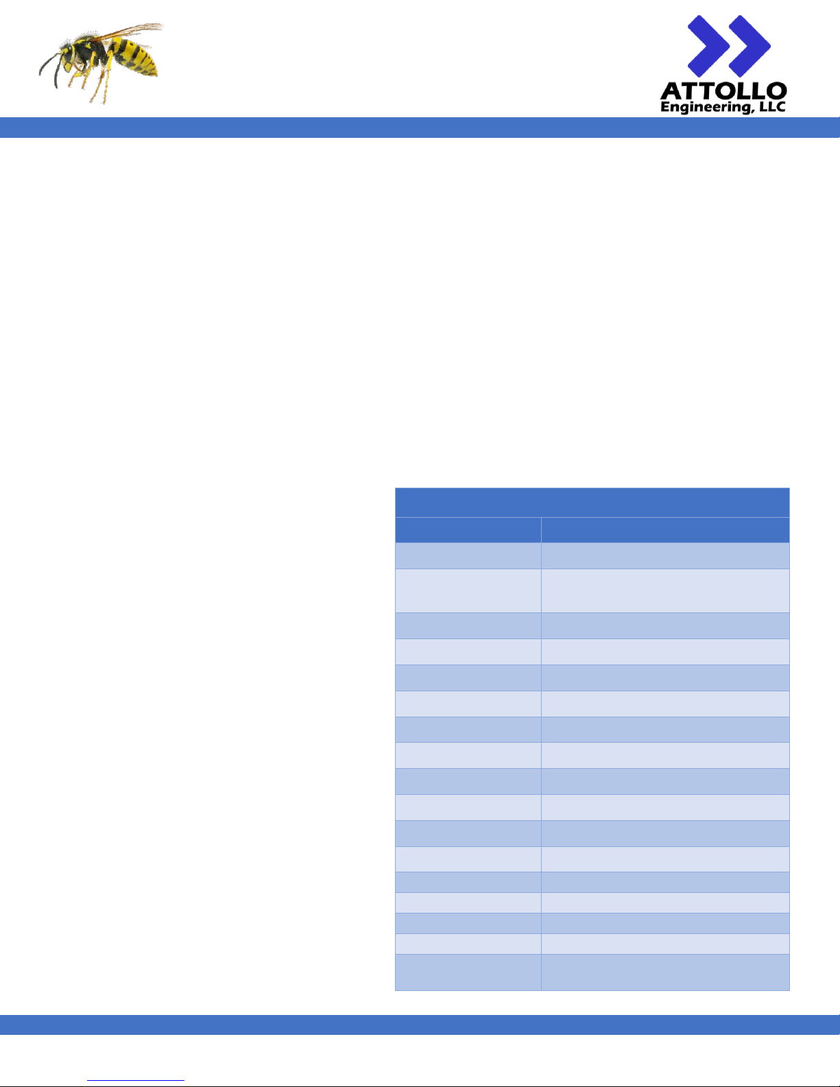
Table 1 - Performance specifications of the WASP-200 LRF.
Specification / Feature
FDA Laser Classification
Range Performance
(Scattering Sunlit Target)
Maximum Range
Accuracy
Resolution
Update Rate
Wavelength
Beam Divergence
Optical Aperture
Input Voltage
Current @ 1 Khz
Inrush Current
Connector
Communication Interface
Dimensions ( L x W x H )
Weight
Operating Temperature
UART (CU1/MU1), CAN/RS-232 (MC1)
44 x 20 x 42 mm3 (CU1/MU1)
26 grams (CU1)
-40 to + 60 C
(-40 to 140 °F)
8 mrad x 1 mrad
18 mm
5V to 16V (CU1/MU1)
7V to 13.8V (MC1)
< 75mA @ 5V Operating Voltage (CU1/MU1)
< 100mA @ 5V Operating Voltage (CU1/MU1)
8 pin Hirose Connector, Pigtail, or IP67 ODU
905 nm
WASP-200 LRF
0.2m to 125m - 18% reflectivity
0.2m to 200m - 80% reflectivity
315 meters
< 10 cm
1 cm
CU1/MU1/MC1
This is a CLASS 1 Laser Product
Single shot to 56 Hz
Page 6
WASP-200 LRF
200m Compact Laser Rangefinder
User Manual
XM000002 Rev. 004
5
Laser Safety
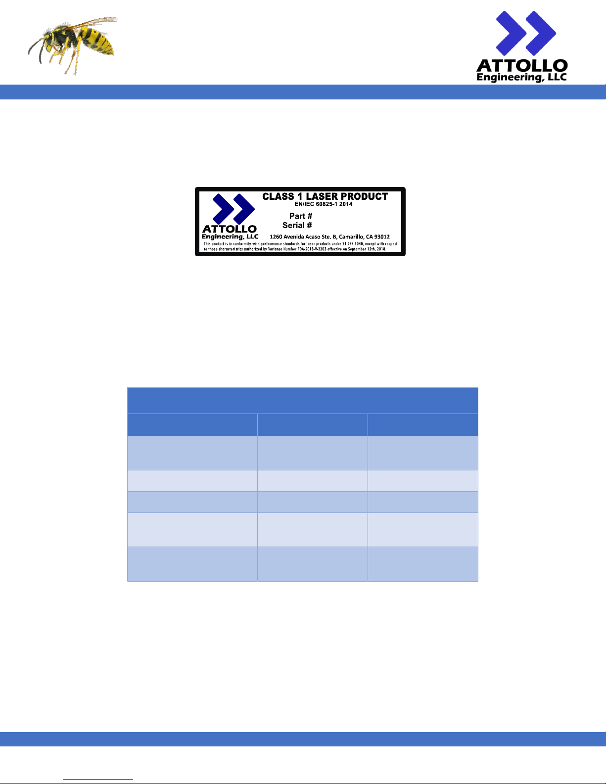
The WASP uses a 905 nm, 75 W peak power laser with a beam divergence of 8 mrad x 1 mrad out of an 18 mm aperture.
NOTE: This Laser Product is designated as Class 1 during all aspects of operation. The U.S. FDA Laser Classification Label
is shown below in Figure 2. The placement of the labels is shown in Figure 3 and Figure 4.
Figure 2 - U.S. FDA Class 1 Laser Label
Physical
There are two configurations of the WASP-200 LRF: Commercial (CU) and Ruggedized (MU and MC). The commercial
version features an injection molded plastic housing and a UART interface over a Hirose DF13 8-pin connector. The
ruggedized version utilizes a machined plastic housing base unit with IP67-designed sealing and an accessory module that
provides a CAN & RS-232 or a UART interface to the host system.
Table 2 - WASP-200 physical device configurations.
Two options for mounting the WASP in a system have been provided.
Option 1 – Rear mounting: There are four 0.150” diameter holes on the rear cover dog ears to flush mount the
unit to a mounting surface. The holes are well-suited for a close clearance with a #6-32 socket head cap screw or
they can be drilled out for slightly larger screws.
Option 2 – Front mounting: The WASP-200 LRF can be mounted to a host-system by way of the 0.067” holes found
on the front of the device and be flush-mounted to a 3/16” plate or panel. The mounting hole can be tapped for
a #2-56 thread.
Specification / Feature Commercial (CU1) Ruggedized (MU1/MC1)
Dimension ( L x W x H )
44 x 20 x 42 mm
3
(1.7 x 0.8 x 1.5 in3 )
44 x 34.8 x 42 mm
3
(1.7 x 0.8 x 1.5 in3 )
Connector
Hirose DF13 ODU IP67
Water Protection
Splash Resistant IP67 Rating
Weight
26 grams
(0.92 oz.)
35 grams (TBD)
(1.24 oz.)
Operating Temperature
-40 to + 60 C
(-40 to 140 °F)
-40 to + 60 C (TBD)
(-40 to 140 °F)
WASP-200 LRF
Page 7
WASP-200 LRF
200m Compact Laser Rangefinder
User Manual
XM000002 Rev. 004
6
Dimensions
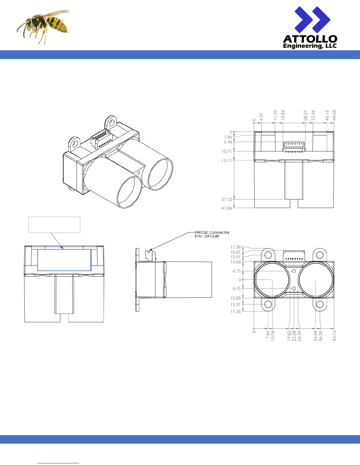
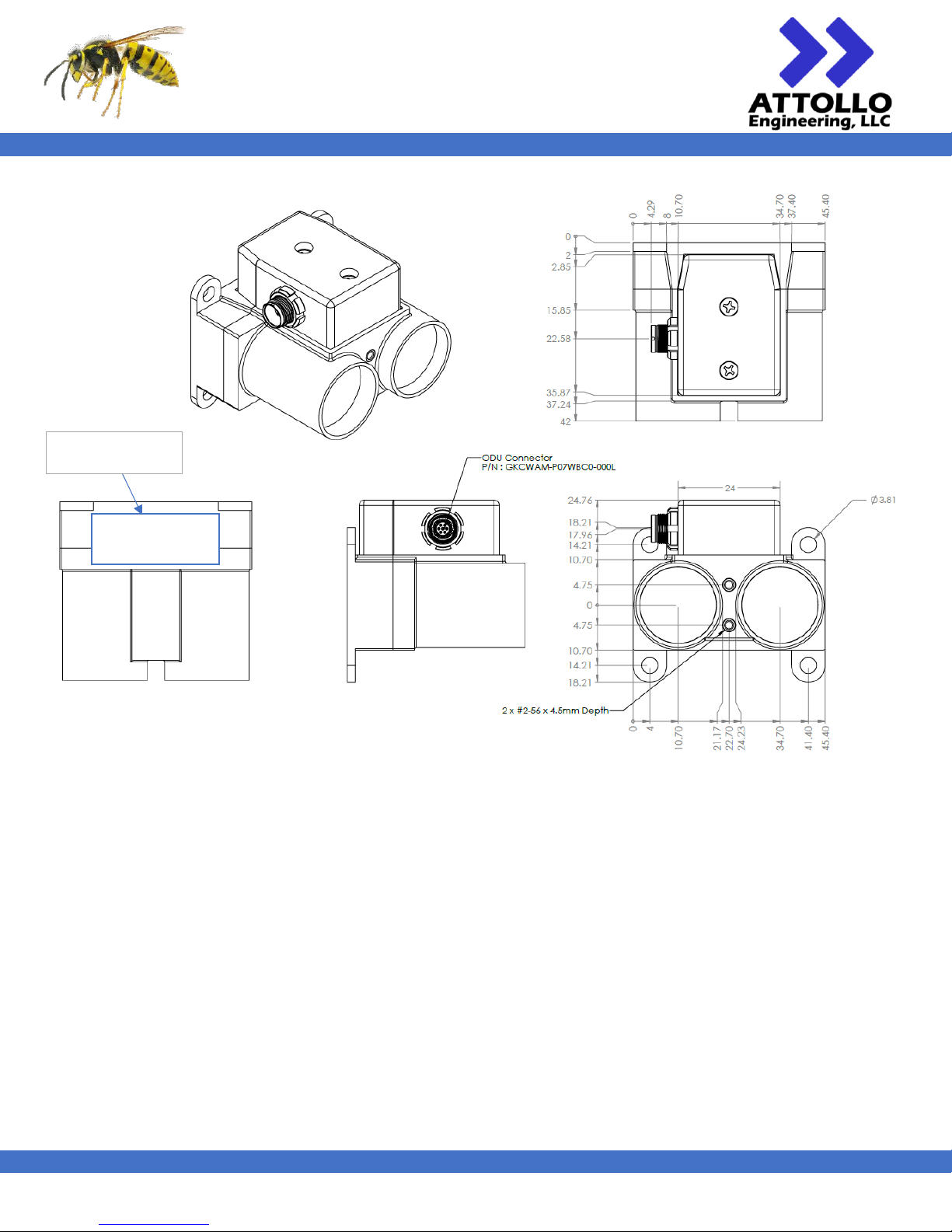
The exterior dimensions and mounting details of the WASP-200 LRF are shown in Figure 3 for the commercial system and
Figure 4 for the ruggedized system. All dimensions are in millimeters. Contact Attollo Engineering for a 3D solid model.
Figure 3 - Exterior and Mounting of the WASP-200 LRF (CU1)
.
FDA CLASS 1 LASER
LABEL LOCATION
Page 8
WASP-200 LRF
200m Compact Laser Rangefinder
User Manual
XM000002 Rev. 004
7
Figure 4 - Exterior and mounting dimensions of the Ruggedized WASP-200 LRF (MU1 and MC1)
FDA CLASS 1 LASER
LABEL LOCATION
Page 9
WASP-200 LRF
200m Compact Laser Rangefinder
User Manual
XM000002 Rev. 004
8
Pinout and Electrical Interface
CU1
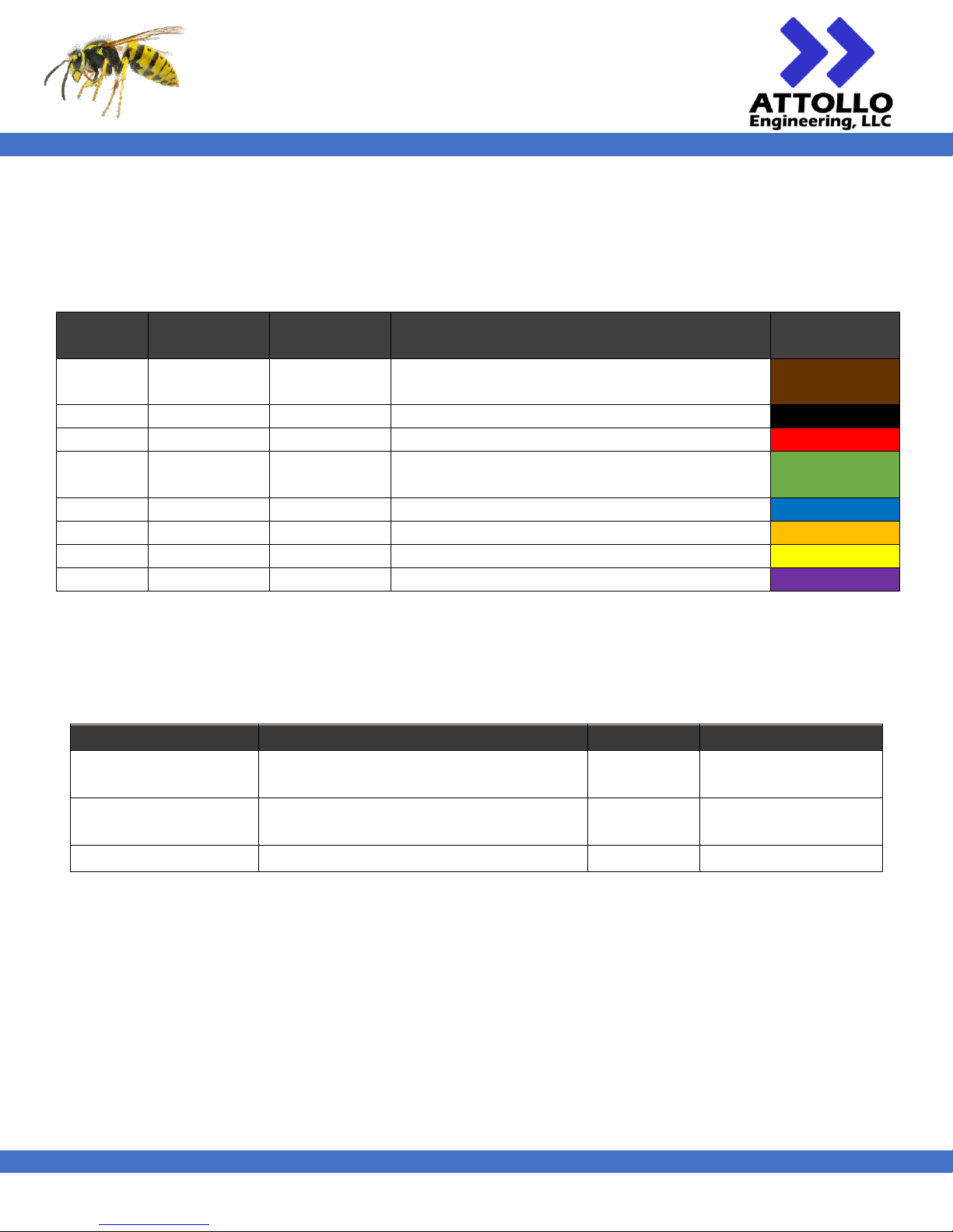
The signals used in operation of the commercial WASP-200 LRF (CU1) are shown in the following table. The user is free to
make their own cable set but cables received from Attollo will be colored per the table below.
Table 3 - WASP-200 LRF Signal Pinouts for the CU1 model.
Pin #
(CU1)
Signal
Voltage Range
Comment
Color
1
RST
0 - 3.3V
3.3V or float for normal operation
0V for greater than 10 us to reset system
Brown
2
GND
0V Black
3
POWER IN
3.5 - 16V
Red
4
POWER
ENABLE
3.3V or connect to POWER IN to enable system
0V or float to disable system
Green
5
UART RX
0 - 3.3V
5V tolerant
Blue
6
UART TX
0 - 3.3V
Orange
7
DIGITAL OUT
0 - 3.3V
Yellow
8
DIGITAL IN
0 - 3.3V
5V tolerant
Purple
Eight plated through holes, on a 1.25 mm pitch are provided on the PCB tab of the WASP-200 LRF for direct soldering of
interface wires or an 8-pin, 1.25mm pitch connector. Most WASP-200 LRFs ship with a Hirose DF13-8P-1.25DS(20) 8-pin
connector though others will work. Recommended connectors and mating components are listed in Table 4.
Table 4 - Recommended connectors and wires for the WASP-LRF CU1 model.
Part
Description
Mfg
Mfg P/N
Board Connector
8 Position Header Connector 0.049"
(1.25mm) Through Hole, Right Angle Tin
Hirose
DF13-8P-1.25DS(20)
Wire Housing / Mating
Connector
8 Position Rectangular Housing Connector
Receptacle Beige 0.049" (1.25mm)
Hirose
DF13-8S-1.25C
Wire
26 – 30 AWG Wire
-
-
Page 10
WASP-200 LRF
200m Compact Laser Rangefinder
User Manual
XM000002 Rev. 004
9
MU1
The MU1-001 uses a 7-pin circular IP67-rated connector from ODU for the power, communication, and I/O connection to
the LRF.
Table 5 - MC1-0017-pin circular connector and mating part.
MU1-001 Connector
ODU GKCWBM-P07WBC0-000L
Mating Connector
ODU A1CWBM-P07XBC0-0000
Note that the MU1-001 uses use the “B” keyway of this connector family. The MU1-001 connector, from the perspective
of looking at the connector from the outside of the LRF, is numbered according to Figure 7.
Figure 5 - MU1 - 7 Pin Circular Connector (ODU GKCWBM-P07WBC0-000L) pin numbering. Minor keyway information in drawing may not be
accurate but pin numbering with respect to the large key is accurate.
The pinout of the connector is defined in Table 8. Mating connectors and cable sets can be purchased from Attollo and
are color coded as indicated in Table 8.
Table 6 - WASP-200 LRF Signal Pinouts for the CU1 model.
Pin #
(MU1)
Signal
Voltage Range
Comment
Color
1
RST
0 - 3.3V
3.3V or float for normal operation
0V for greater than 10 us to reset system
Brown
Shell/Drain
GND
0V Black
7
POWER IN
3.5 - 16V
Red
5
POWER
ENABLE
3.3V or connect to POWER IN to enable system
0V or float to disable system
Grey
2
UART RX
0 - 3.3V
5V tolerant
Blue
4
UART TX
0 - 3.3V
Orange
6
DIGITAL OUT
0 - 3.3V
Yellow
3
DIGITAL IN
0 - 3.3V
5V tolerant
Purple
*Note that there are two black wires on the pigtail end of the cable. However, one is heatshrink wrapped and is not fully
insulated at the base where it meets the thick plastic insulation. This is the cable braid / drain of the cable. The black GND
signal is stripped only at the tip like all of the other wires.
Page 11
WASP-200 LRF
200m Compact Laser Rangefinder
User Manual
XM000002 Rev. 004
10
Minimum Recommended Configuration (CU1 and MU1)
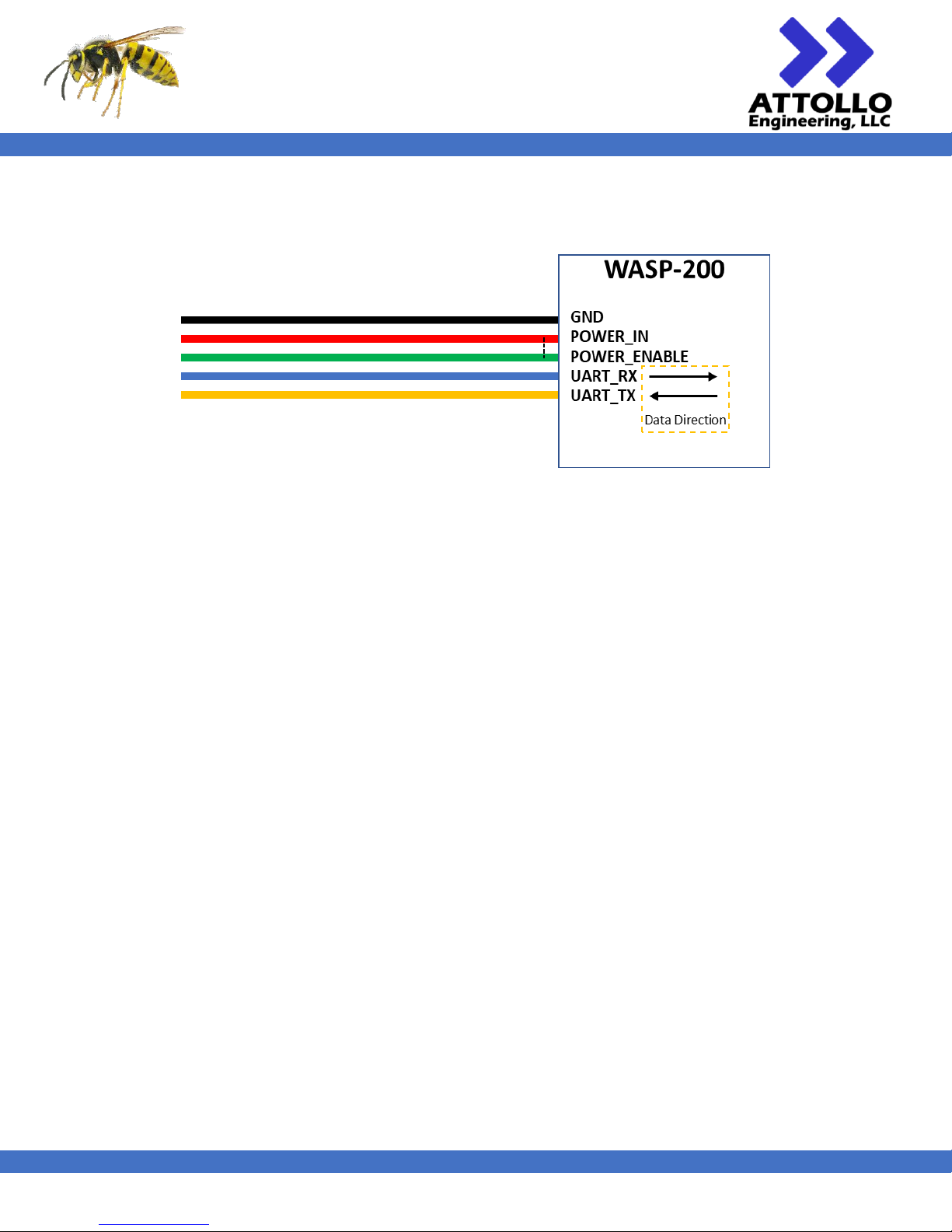
To operate the WASP-200 LRF with a minimal electrical configuration the cable can be configured like that shown in Figure
6.
Figure 6 - The minimum required connections to operate the WASP-LRF
POWER_ENABLE can be tied to POWER_IN to simplify the number of connections. POWER_ENABLE can tolerate the full
voltage range (4.7V – 16 V) of POWER_IN.
Page 12
WASP-200 LRF
200m Compact Laser Rangefinder
User Manual
XM000002 Rev. 004
11
MC1
The MC1-001 uses a 7-pin circular IP67-rated connector from ODU for the power, communication, and I/O connection to
the LRF.
Table 7 - MC1-0017-pin circular connector and mating part.
MC1-001 Connector
ODU GKCWAM-P07WBC0-000L
Mating Connector
ODU A1CWAM-P07XBC0-0000
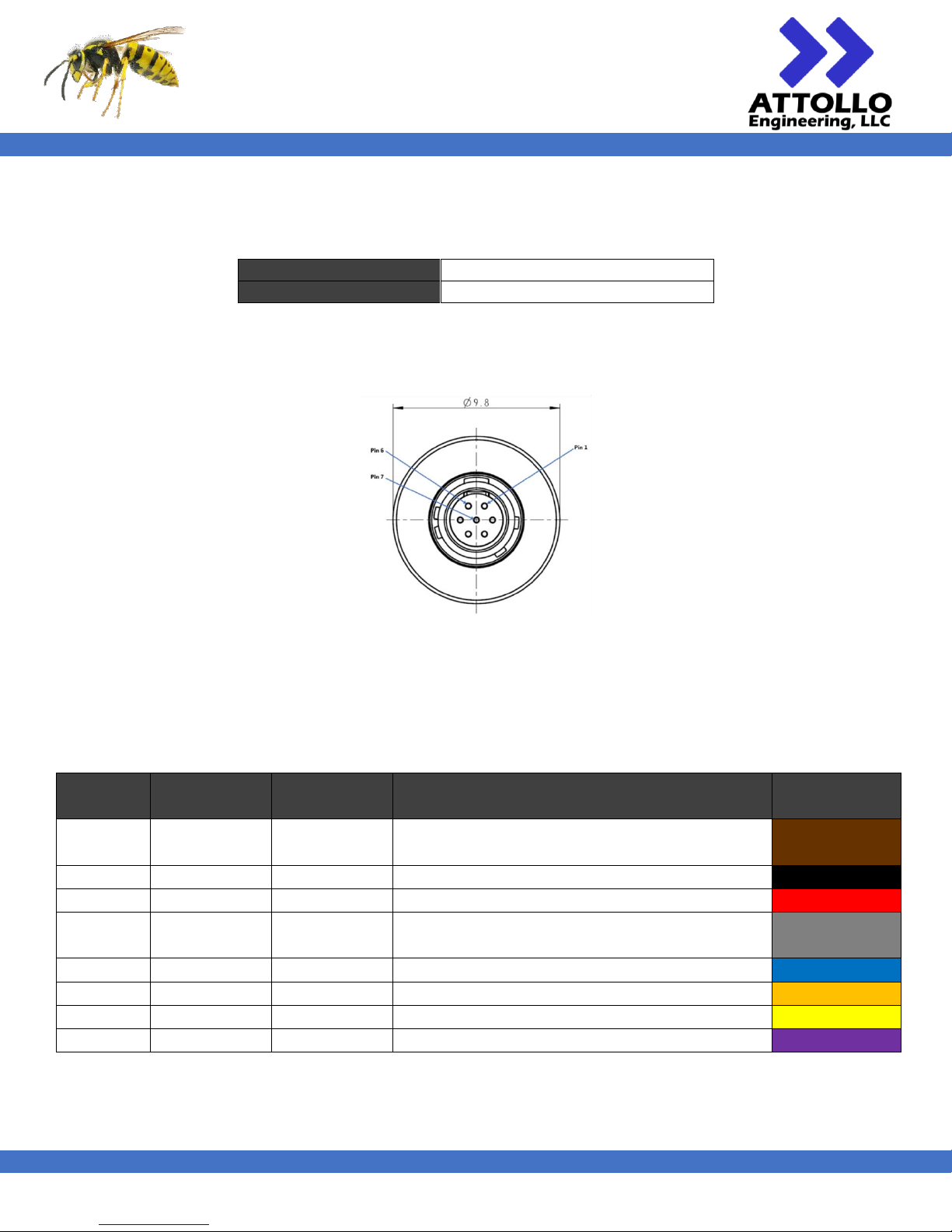
Note that the MC1-001 uses use the “A” keyway of this connector family. The MC1-001 connector, from the perspective
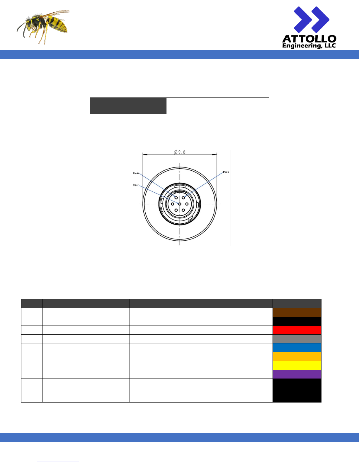
of looking at the connector from the outside of the LRF, is numbered according to Figure 7.
Figure 7 - MC1 - 7 Pin Circular Connector (ODU GKCWAM-P07WBC0-000L) pin numbering
The pinout of the connector is defined in Table 8. Mating connectors and cable sets can be purchased from Attollo and
are color coded as indicated in Table 8.
Table 8 - WASP-200 LRF Signal Pinouts for the MC1 model.
Pin #
Signal
Voltage Range
Comment
Color
1
RS-232 RX
0 - 3.3 V
Brown (or Gray)
6
RS-232 TX
0 - 3.3 V
Black
2
POWER IN
7 to 13.8 V
Red (or Pink)
3
CAN N
0 - 5 V
Green
7
GPIO
0 - 5 V
Blue
5
GND
0 V
Orange
4
CAN P
0 - 5 V
Yellow
NA
SHIELD
-
Should be tied to GND on customer end of cable
Purple
NA
SHIELD
-
Cable braid / drain – connected to shield
Black –
heatshrink
wrapped
*Note that there are two black wires on the pigtail end of the cable. However, one is heatshrink wrapped and is not fully
insulated at the base where it meets the thick plastic insulation. This is the cable braid / drain of the cable. The black
RS-232 TX signal is stripped only at the tip like all of the other wires.
Page 13
WASP-200 LRF
200m Compact Laser Rangefinder
User Manual
XM000002 Rev. 004
12
The CAN Bus is terminated within the MC1-001 with a 120 Ω resistor. It is recommended that the user provide the
appropriate termination within their system which is recommended to be a corresponding 120 Ω resistor on the host end
of the system.
The MC1-001 can accept an input voltage from 7 to 13.8 V. Power consumption under steady state is approximately
800 mW. When enabling the LRF the system demands an inrush current for up to 5 ms. When connected directly to a
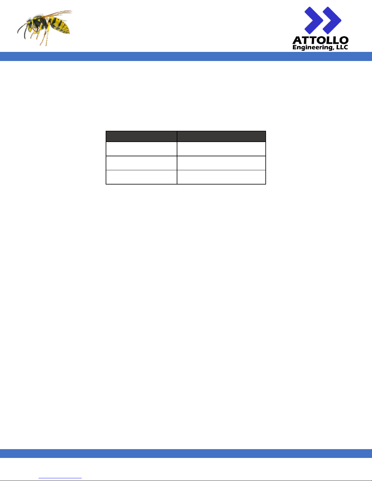
power supply, the current compliance limits shown in Table 9 provided adequate supply current during this inrush period.
Table 9 - Maximum current required at the specified operating voltage to support the inrush current when enabling the LRF
Operating Voltage (V)
Maximum Current (mA)
7
500
10
150
13.8
100
Many electronic component distributors may sell pre-crimped wires of varying lengths and colors if you wish to build your
own cable set. Attollo also sells pre-assembled cable assemblies with the DF13 and ODU connectors described above and
color coded in accordance with the corresponding pinouts. Attollo sells a USB to UART adapter board for communicating
with the WASP-200 LRF over a computer’s serial interface. Visit the website for configuration and ordering information.
Page 14
WASP-200 LRF
200m Compact Laser Rangefinder
User Manual
XM000002 Rev. 004
13
Communication Interface (CU1 and MU1)
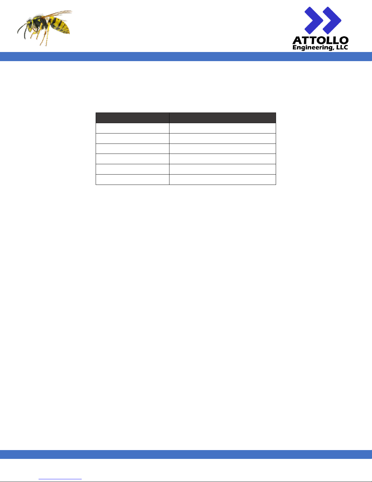
The WASP-200 LRF provides a UART serial interface for communication. The UART communication settings are
summarized in Table 10. The following section will provide detail on the command structure used for communicating with
the WASP-200 LRF.
Table 10 - WASP-LRF UART communication settings
Specification
Measurement
Baud Rate
115200 & 921600
Data Bits
8
Stop Bits
1
Parity
None
Flow Control
None
Terminating Character
Linefeed (Hex: 0x0A)
All serial commands must append a linefeed character at the end in order to be properly received by the WASP-200 LRF.
Page 15
WASP-200 LRF
200m Compact Laser Rangefinder
User Manual
XM000002 Rev. 004
14
Serial Commands
Communicating with the CU1 and MU1 variants of the WASP-200 LRF takes place through the serial command interface
using ASCII-based commands. Each command to the LRF consists of an initialization character, a command mnemonic,
and zero or more arguments. All commands are case sensitive and are UPPER CASE. The initialization character for all
commands being transmitted to the rangefinder is the “>” character. For example:
>RNG
All serial commands must append a linefeed character at the end (ASCII (hex) 0x0A, ‘\n’) to be received by the LRF.
ASCII responses from the WASP-200 LRF follow a similar format, except the initialization character is the “<” character.
The initialization character can also be helpful as a dataflow direction indicator.
At power-on, after the WASP-200 has initialized, it will report it’s model name (MNM), hardware revision (MHV), serial
number (MSN), firmware version (MFW), and manufacturer (MFG). Receipt of these responses indicates the WASP-200 is
ready to receive commands and begin ranging.
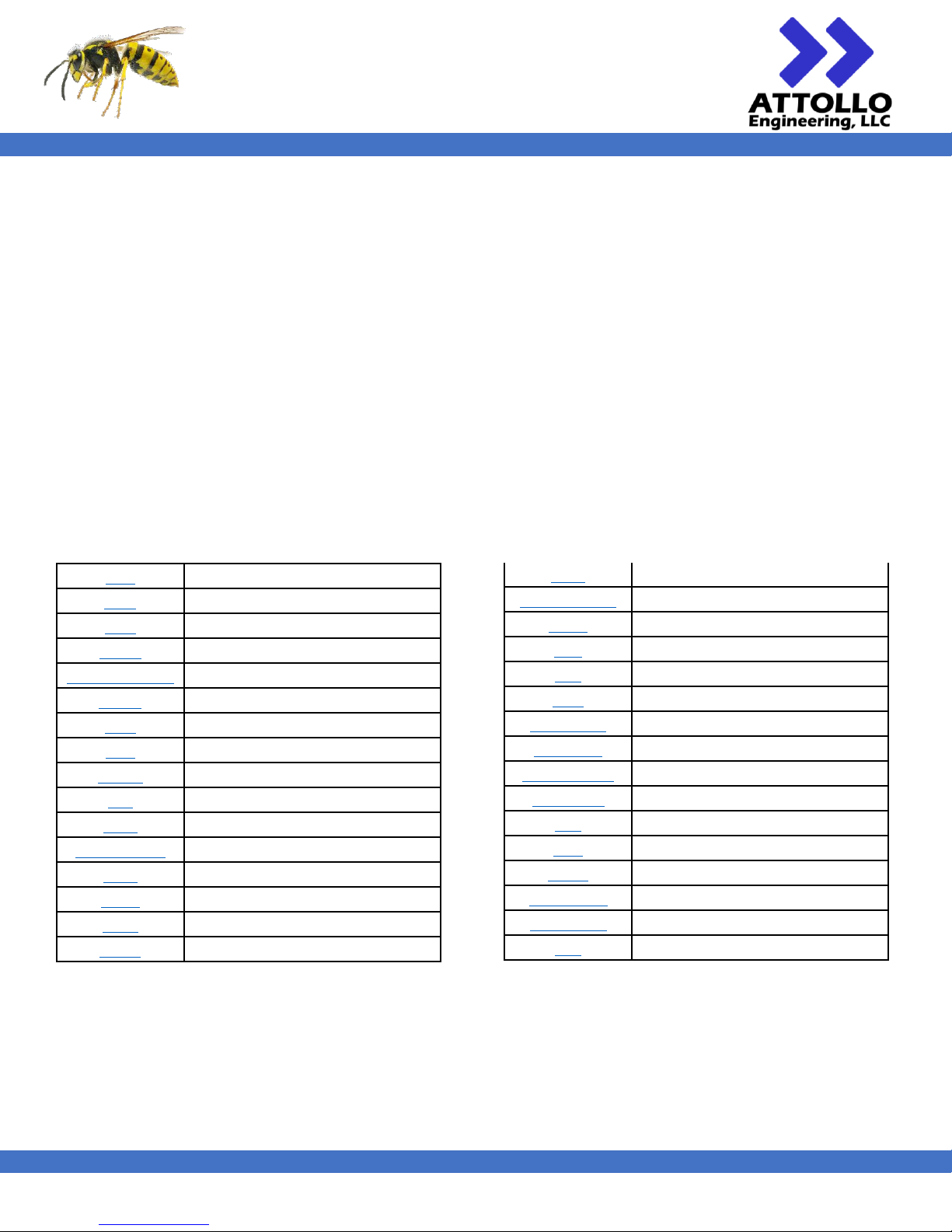
The available commands for use with the WASP-200 LRF are:
AUT
Auto-threshold enable / disable
AUV
Auto-voltage enable / disable
AVG
Number of multi-pulse averages
BAUD
Baud rate of UART interface
CHK (CHKSUM)
Add 16-bit checksum to output
DCM?
Detector dark current
FMT
Output format
FRQ
Continuous ranging frequency
HLTH?
Health check
LBE
Binary output format endianess
LOM
Legacy Output Mode
MDF (MEDF)
Median-filter window size
MFG
Manufacturer
MFW
Model firmware version
MHV
Model hardware version
MNM
Model name
MSN
Model serial number
MVG (MAVG)
Moving average
NSG?
Detector noise
OFS
Range offset in meters
RBF
Reset range buffer
RNG
Single range
RST (RSTB)
Software reset
RUN (GO)
Start continuous ranging
SAV / (SAVE)
Saves current settings to flash
SET (SET?)
Current settings
STP
Stop continuous ranging
THR
Sensitivity threshold
TMP?
System temperature
TOS (TOFS)
Sensitivity threshold offset
TRG (TRIG)
Triggered ranging
VLT
APD bias voltage
Page 16
WASP-200 LRF
200m Compact Laser Rangefinder
User Manual
XM000002 Rev. 004
15
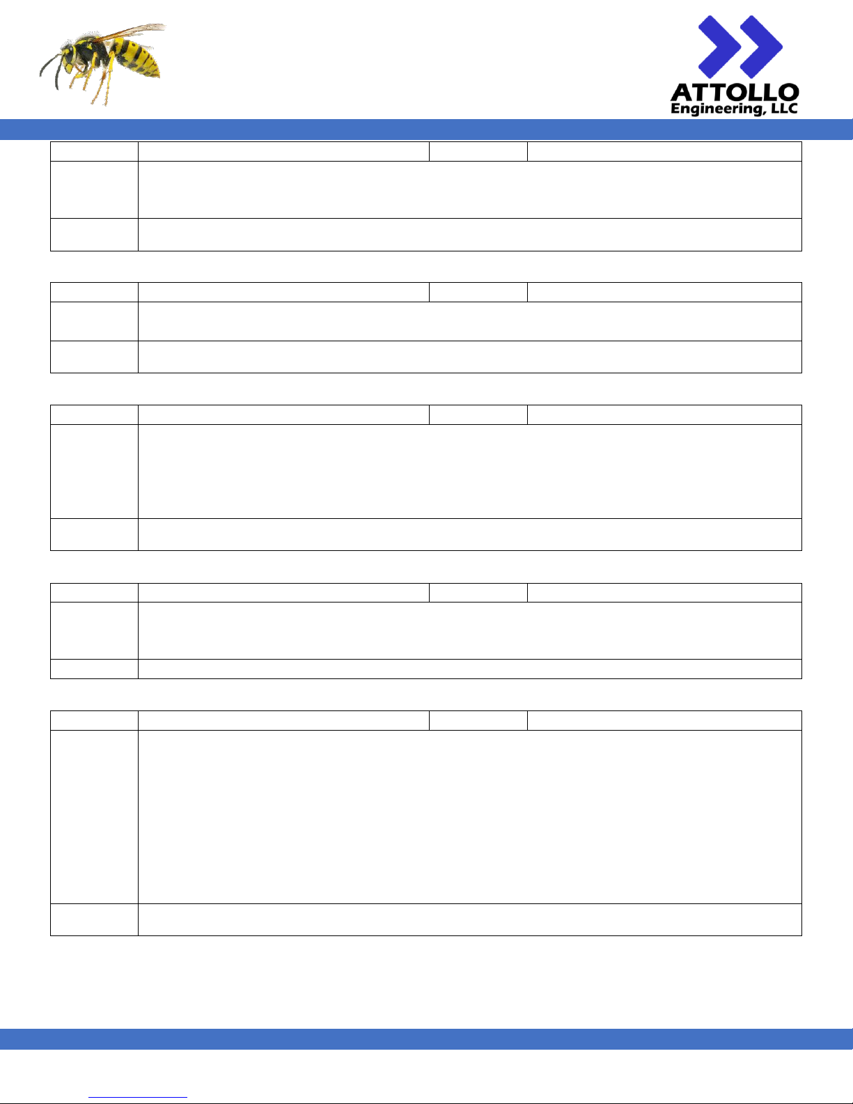
Command
AUT
Arguments
[0/1]
Description
Enables (1) and disables (0) the auto-threshold adjustment. The auto-threshold feature ensures that the
system is in its highest sensitivity state, while still ensuring a better than 1% false alarm rate, before every
range measurement.
Example
>AUT 1
< AUT1
Command
AUV
Arguments
[0/1]
Description
Enables (1) and disables (0) auto-voltage adjustment. Auto-voltage adjustment maintains the sensitivity
of the system over changes in the LRF’s ambient environment.
Example
>AUV 0
< AUV0
Command
AVG
Arguments
[1…32]
Description
Sets the number of pulses to be used in multi-pulse averaging mode. In this mode, a sequence of rapid-fire
ranges are taken and then averaged to improve the accuracy of the measurement. Each range operation
takes approximately 100 us to complete so the number of averages multiplied by 100 us should not
exceed 1/FRQ. The LRF will prioritize maintaining the ranging frequency and will reduce the number of
averages taken to remain within compliance with the Class 1 classification.
Example
>AVG 8
< AVG8
Command
BAUD
Arguments
[HIGH/LOW]
Description
Sets the baud rate of the UART communication interface. A value of HIGH will set the baud rate to 921600
bps and a value of LOW will set the baud rate to 115200 bps. Baud rate changes will take effect upon
issuance of the command.
Example
>BAUD HIGH
Command
CHK (CHKSUM)
Arguments
[0/1]
Description
Enables (1) and disables (0) the reporting of a checksum with every range report. The checksum is
calculated as 16-bit with a polynomial of 1021 and an initial value of 0.
When enabled, the range response will look like the following:
< 10.145d|
< 10.459ô+
< 11.074ú*
< 11.089N0
< 11.104ÑÂ
where the two bytes after the 3 decimal point precision range response represent the binary-encoded
checksum.
Example
>CHKSUM 1
< CHKSUM1
Page 17
WASP-200 LRF
200m Compact Laser Rangefinder
User Manual
XM000002 Rev. 004
16
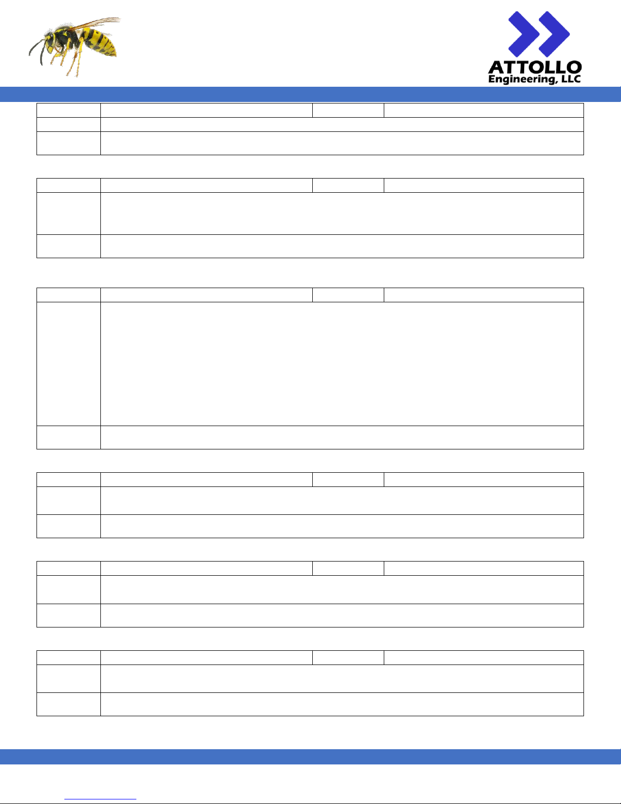
Command
DCM?
Arguments
None
Description
Reports the current detector dark current value in arbitrary units.
Example
>DCM?
< DCM?312
Command
FMT
Arguments
[BINARY/ASCII]
Description
Sets the output format for range reporting. ASCII will report range data as a 3 decimal precision floating
point number. BINARY will report range data as a 32-bit floating point number. Regardless of the output
format mode, the WASP-200 LRF always expects inputs in ASCII format.
Example
>FMT BINARY
< FMT BINARY
Command
HLTH?
Arguments
None
Description
Reports a summary of various health aspects of the rangefinder including dark current, temperature,
noise level, whether ranging is presently active, and any current system errors.
Example
>HLTH?
< DCM?0 | TMP?024.82 | NSG?5280 | ACT?0 | ERR?0
Command
LBE
Arguments
[BIG/LITTLE]
Description
Sets the endian-ness of the BINARY output during range reporting. LBE has no effect when the output
format is ASCII. The default endian-ness is BIG.
Example
>LBE LITTLE
< LBE LITTLE
Command
LOM
Arguments
[0/1]
Description
Sets the output formatting to that of the early version of the wasp with a line break before the range
result for the RNG command and no carrots on each line of range results for the RUN command
Example
>LOM 1
< LOM1
Command
FRQ
Arguments
[1…56]
Description
Sets the repetition frequency of the ranging operation in Hertz. XXXX is the desired frequency of
operation. Upon entering the desired frequency, the system will calculate the nearest frequency that it
can handle according to the U.S. FDA Laser Classification of the product and/or resolution of internal
timers. This value will be reported back to the user. The frequency can be set / changed within this
frequency range when the system is either active or idle.
To remain Class 1 compliant, the LRF must never exceed 56 laser pulse outputs within a 1 second time
period. Therefore, if the averaging function is being used, where the LRF sends out a burst of pulses and
averages the results, the LRF will prioritize maintaining the ranging frequency and will reduce the number
of averages taken to remain within compliance with the Class 1 classification.
Example
>FRQ 50
< FRQ50
Page 18
WASP-200 LRF
200m Compact Laser Rangefinder
User Manual
XM000002 Rev. 004
17
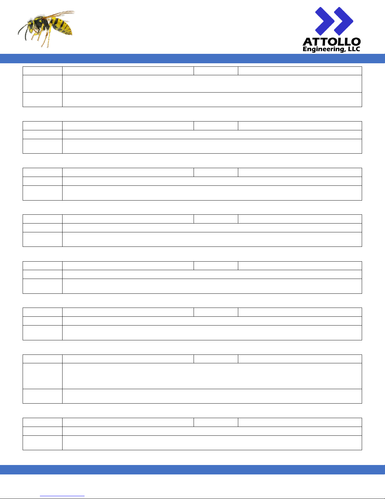
Command
MFG
Arguments
None
Description
Reports the manufacturer of the WASP-200 LRF.
Example
>MFW
< MFW ATTOLLO ENGINEERING
Command
MFW
Arguments
None
Description
Reports the WASP-200 LRF firmware version.
Example
>MFW
< MFW 18410001
Command
MHV
Arguments
None
Description
Reports the hardware revision of the WASP-200 LRF.
Example
>MHV
< MHV 100
Command
MNM
Arguments
None
Description
Reports the model name of the WASP-200 LRF.
Example
>MNM
< MNM CU1-001
Command
MSN
Arguments
None
Description
Reports the serial number of the WASP-200 LRF.
Example
>MSN
< MNM 18380007
Command
MVG (MAVG)
Arguments
[1…64]
Description
Sets the number of historic range results to use for calculating the current range result. When MVG is
greater than 1, the current range result will be the current measured value averaged with the N-1 previous
results.
Example
>MVG 10
< MVG10
Command
NSG?
Arguments
None
Description
Reports the current system noise in arbitrary units.
Example
>NSG?
< NSG?64
Command
MDF (MEDF)
Arguments
[1…32]
Description
Sets the window size for the real-time median filter. When MDF is greater than 1 the median filter is
active.
Example
>MDF 8
< MDF8
Page 19
WASP-200 LRF
200m Compact Laser Rangefinder
User Manual
XM000002 Rev. 004
18
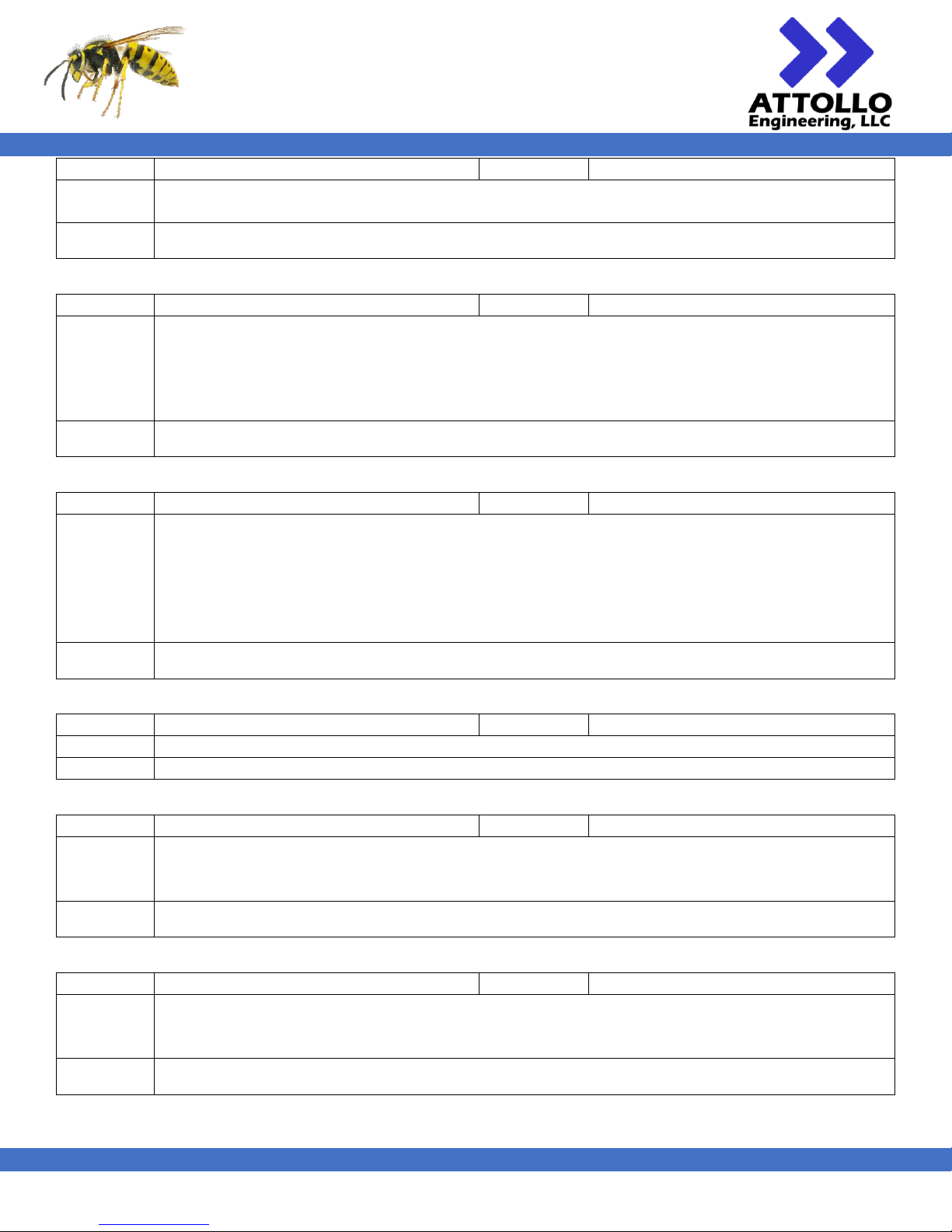
Command
OFS
Arguments
[-10.0…10.0]
Description
Applies an offset to the reported range. Valid arguments can be negative or positive floating point
numbers.
Example
>OFS 0.23
< OFS0.230
Command
RBF
Arguments
None
Description
Resets the range buffer. The range buffer is a 64-element queue of the last 64 ranges that is used for
carrying out the moving average (MVG) and median filter (MDF) functions. Resetting the range buffer
may be useful if the user suspects that stale range data may be in the queue (i.e. there was a break in the
ranging while the vehicle was still moving) and the user wishes to use the moving average or median
filter.
Example
>RBF
< RBF
Command
RNG
Arguments
None
Description
Executes a single shot range operation and returns a single range result. The range result is reported
according to the formatting options selected using the FMT and LBE commands. Assuming ASCII
formatted output (FMT ASCII) the range result will be a floating point number with 3 decimal points
of precision. All ranges are referenced from the rear of the unit. The OFS command can be used to apply
an offset to this reference datum. The RNG command can be called sequentially and will limited to 56
Hz. Exceeding this rate will result in a “RANGE_NOT_READY” error code (-6).
Example
>RNG
< 5.832
Command
RST (RSTB)
Arguments
None
Description
Conducts a software reset of the WASP-200 LRF.
Example
>RST
Command
RUN (GO)
Arguments
None
Description
Starts continuous ranging at the frequency specified by FRQ. The range results will be reported in the
format specified by the FMT and LBE parameters. By default, the range result is reported as plain text
ASCII floating point number with 3 decimal places of resolution.
Example
>RUN
< RUN
Command
SAV (SAVE)
Arguments
None
Description
Saves all currently active user parameters to the non-volatile flash memory. The WASP-200 LRF will
re-load these parameters after the next software or power-on reset. The currently active user parameters
can be viewed using the SET command.
Example
>SAV
< SAV
Page 20
WASP-200 LRF
200m Compact Laser Rangefinder
User Manual
XM000002 Rev. 004
19
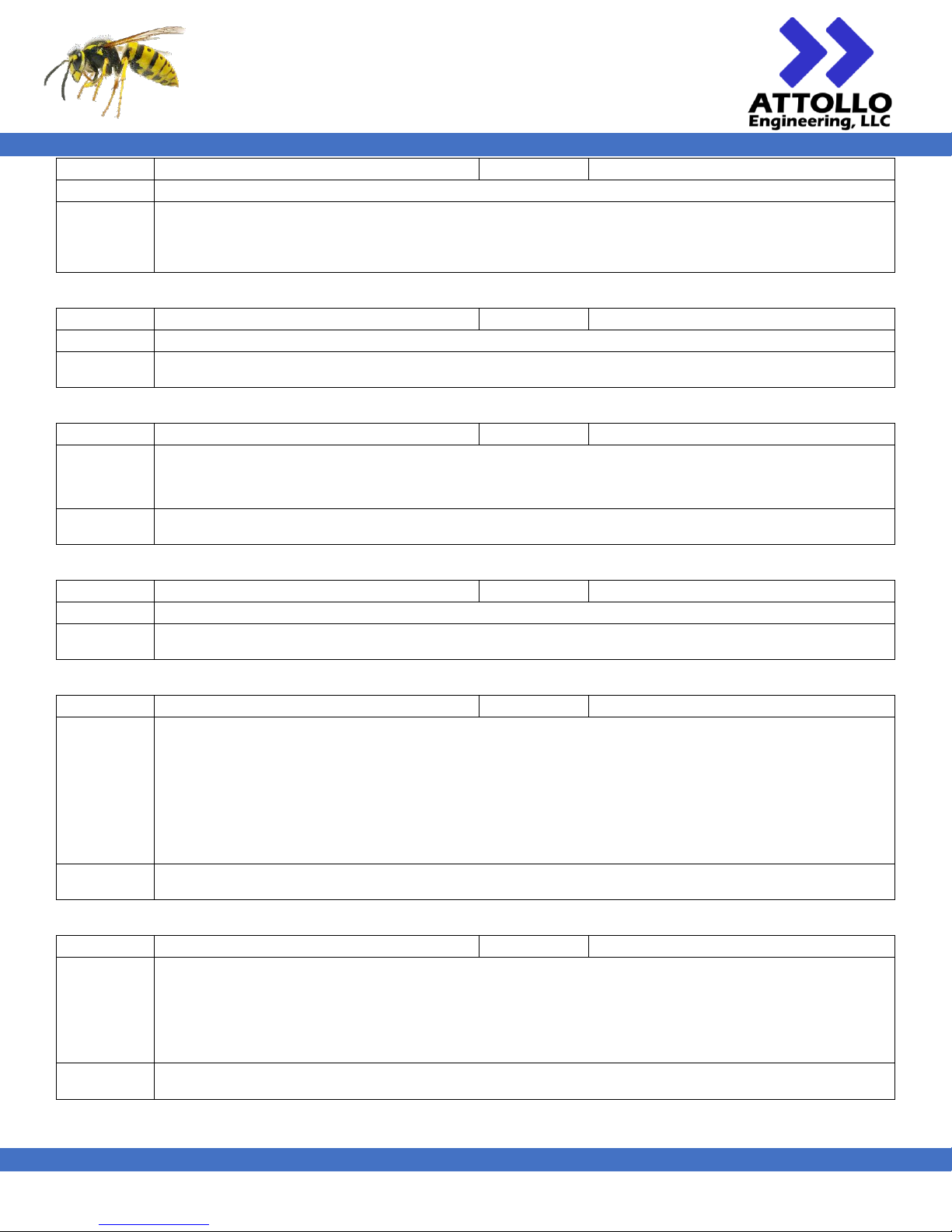
Command
SET (SET?)
Arguments
None
Description
Reports the current system parameters.
Example
>SET
< THR220 TOFS0 OFS0.000 FRQ10 VLT677 AVG1 MAVG1 AUT1 AUV1 MEDF1 LBE|BIG
FMT|ASCII CHKSUM1 TRIG0 SAVE1
Command
STP
Arguments
None
Description
Stops continuous ranging.
Example
>STP
< STP
Command
THR
Arguments
[1…255]
Description
Sets the system sensitivity. Larger values of THR represent higher sensitivity. When in auto-threshold
mode the system will control the value of THR to prevent excessive false alarm rates based on settings
made at the factory. The maximum system value is 255.
Example
>THR 240
< THR240
Command
TMP?
Arguments
None
Description
Reports the current system temperature in degrees Celsius.
Example
>TMP?
< TMP? 35.44
Command
TOS (TOFS)
Arguments
[-10…10]
Description
Applies an offset, positive or negative, to the sensitivity threshold (THR) of the rangefinder. The offset
only applies in auto-thresholding mode (AUT1) and is ignored when in manual thresholding mode (AUT0).
Care should be taken such that the sum of TOS and the present THR (without offset applied) value does
not exceed 255 or does not subceed 0, otherwise undesirable behavior may occur.
Typically, useful offset values are small (i.e. absolute value of 1 to 3) and may be used to improve
sensitivity at the expense of a higher false alarm rate or to counteract a strong sunlight on particularly
reflective or specular target.
Example
>TOS 2
< TOS2
Command
TRG (TRIG)
Arguments
[0/1]
Description
Enables (1 or 2) and disables (0) the external range triggering via the DIG_IN pin. A value of 1 enables
rising edge triggered ranging and a value of 2 enables falling edge triggered ranging. The minimum pulse
width in either case must be greater than 1 µs. The active edge rate must not exceed the maximum range
rate of the rangefinder otherwise a RANGE_NOT_READY error will be reported and the request will be
ignored.
Example
>TRG 1
< TRG1
Page 21
WASP-200 LRF
200m Compact Laser Rangefinder
User Manual
XM000002 Rev. 004
20
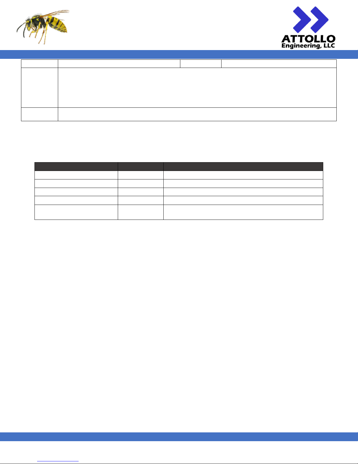
Command
VLT
Arguments
[0…1023]
Description
Sets the APD bias, in arbitrary units. Upon power-up, the system will automatically set the APD bias and
continue to adjust it depending on varying ambient conditions and it should not need to be further
adjusted. However, VLT gives the user the ability to change the bias. Increasing the bias too far past the
start-up value risks over-biasing the APD and causing permanent damage to the APD. You must disable
auto-voltage adjustment (AUV 0) before setting the voltage using the VLT command.
Example
>VLT 510
< VLT510
Range Error Codes
Range error codes are reported by the WASP-200 LRF by a “-“ sign followed by a code instead of the expected range value.
Table11 – WASP-200 LRF UART ERROR Codes
Error
Error Code
Description
RANGE_NULL
-1
No range received from target.
RANGE_MAVG_BUFFER_NOT_FULL
-2
Moving average buffer has not been filled yet.
RANGE_AVG_NULLS
-4
50% or greater of the averaged pulses were NULLs
RANGE_MAVG_BUFFER_NULLS
-5
50% or greater of the ranges in the moving average buffer are NULLs
RANGE_NOT_READY
-6
LRF not ready for range request. Range requested in excess of
maximum allowable range rate (i.e. 56 Hz for Class 1 operation)
Page 22
WASP-200 LRF
200m Compact Laser Rangefinder
User Manual
XM000002 Rev. 004
21
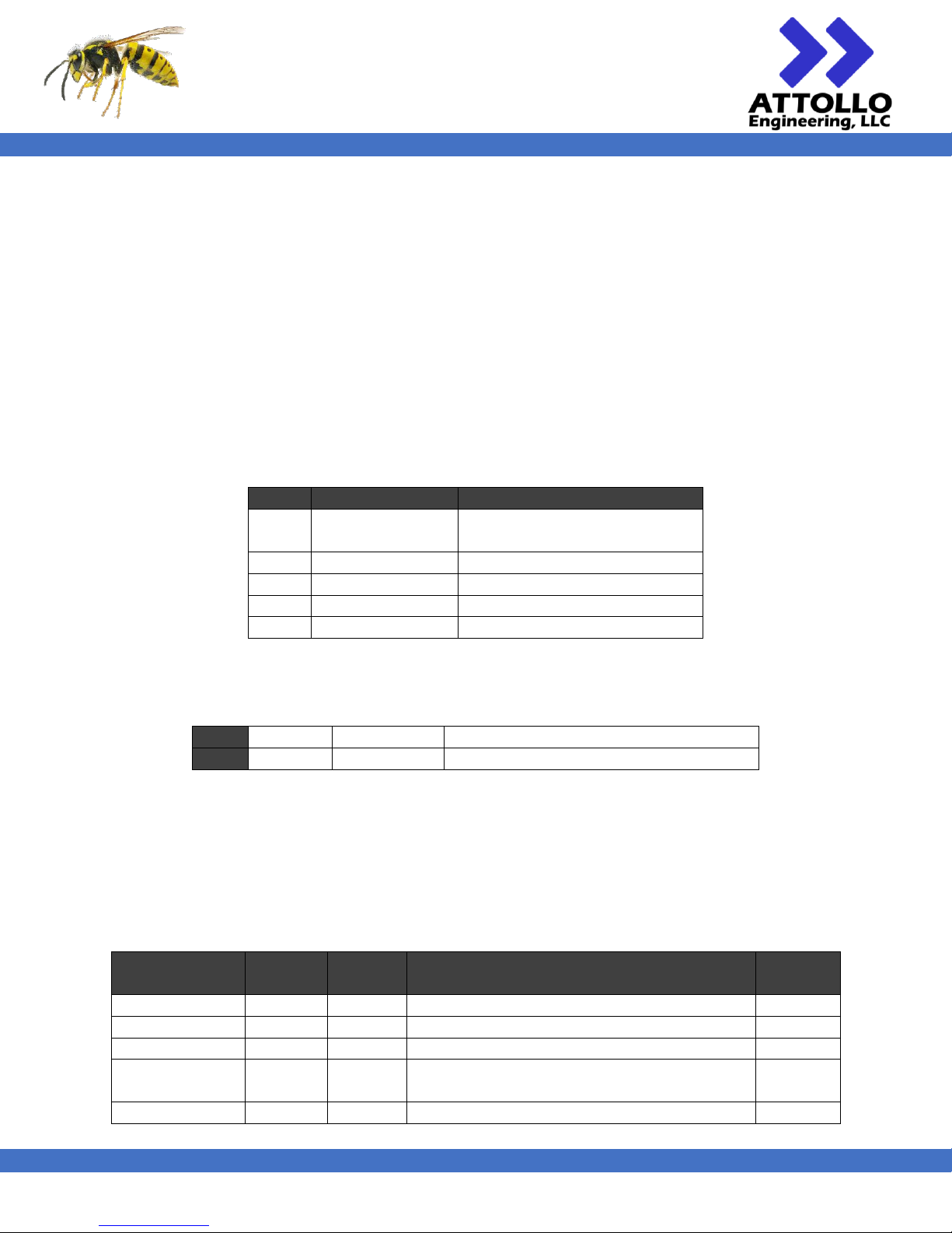
Communication Interface (MC1)
The WASP-200 MC1 LRF has both a CAN interface and an RS-232 serial interface. The CAN interface is formatted according
to the CAN 2.0B standard and is configured to be compliant with the Latitude AGL-M/N communication protocol and
therefore compatible with the Cloud Cap Technologies Piccolo autopilot. The baud rate of the CAN channel is
1,000,000 bps.
Presently the RS-232 interface, operating at 115,200 bps is used solely for configuring the WASP-200 LRF per the Serial
Commands described in the previous section. This is done by using the “>LRF “ mnemonic ahead of the desired command.
In a future version of the MC1 firmware the RS-232 interface will also support the Latitude AGL-M/N RS-232
communication protocol at a baud rate of 9600 bps.
CAN
The CAN frame is formatted as shown in Table 11.
Table 11 - CAN Frame Structure
Field
Name
Description
0
29-bit identifier
See Table 12 for field
description
1
Control
Contains the data length
2
Data
Up to 8 data bytes
3
CRC
CRC sequence
4
ACK
Ack field
The 29-bit identifier bits are broken down into the fields shown in Table 12.
Table 12 - CAN 2.0B Frame Identifier
Bits
0:4
5:12
13:28
Field
Group ID
Message ID
Serial Number. Use “0” for “all broadcast”
CAN Bus Commands
The CAN commands are nearly a complete subset of the Latitude Engineering AGL CAN command set (Title: AGL-CommsInterface, Dated: 12/15/15). This allows the WASP-200 MC1-001 to be a drop-in replacement, communication-wise, with
the Cloud Cap Technology Piccolo family of autopilots. The supported commands are listed in Table 13Table 18 and a
description for the CAN group IDs are shown in Table 14.
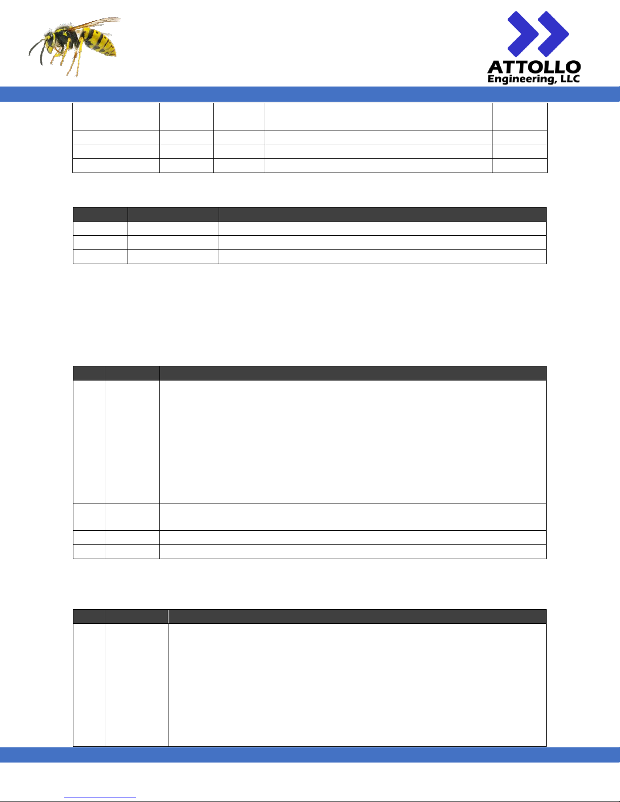
Table 13 -WASP MC1-001 Data Packet Types
Name
CAN
Group ID
Message
ID
Description
Direction
READING
0x04
0x00
Contains the data from a single reading
Down
LASER_MODE
0x04
0x01
Sends sensor setting information to the LRF
Up
SINGLE
0x04
0x02
Requests a single range reading
Up
LASER_MODE_2
0x04
0x03
Sends sensor setting information when
requiring range rates in excess of 20 Hz
Up
CONFIG
0x15
0x0C
System configuration and user settings
Up
Page 23
WASP-200 LRF
200m Compact Laser Rangefinder
User Manual
XM000002 Rev. 004
22
POWER
0x04
0X0E
Controls the ON/OFF state, allows testing, and
sets the startup behavior
Up
EXT_POWER
0x15
0x0E
Controls ON/OFF state via Piccolo uplink
Up
UPDATE_OFFSET
0x04
0x1F
Updates the laser offset calibration
Up
DATE_VERSION
0x04
0xFF
Sends the firmware version and build date
Up/Down
Table 14 - CAN Group IDs
Group ID
Name
Description
0x04
AGL Output
Used for message I/O via the Piccolo External Sensors protocol
0x14
Piccolo Downlink
Used for messages from the AGL Sensor via the Piccolo downlink
0x15
Piccolo Uplink
Used for messages to the AGL Sensor via the Piccolo uplink
CONFIG
This packet allows the user to specify general system settings. Since this packet has the potential to conflict with other
devices on the CAN bus by using the general Piccolo uplink group ID (0x015), a unique identifier has been embedded into
the message to help distinguish it from others. The unique identifier is 0x1A5.
Table 15 - CONFIG packet byte structure
Byte
Name
Description
0
Flags
8-bit flags
Bit 0 (MSB): Enable raw laser reading output over CAN bus - Not used; Always ‘0’
Bit 1: Reserved
Bit 2: Reserved
Bit 3: Reserved
Bit 4: Reserved
Bit 5: Reserved
Bit 6: Reserved
Bit 7: Reserved
1
Flags
8-bit flags
Bit 0-7: Reserved
2
AGL ID0
0x1A (unique identifier)
3
AGL ID1
0x5E (unique identifier)
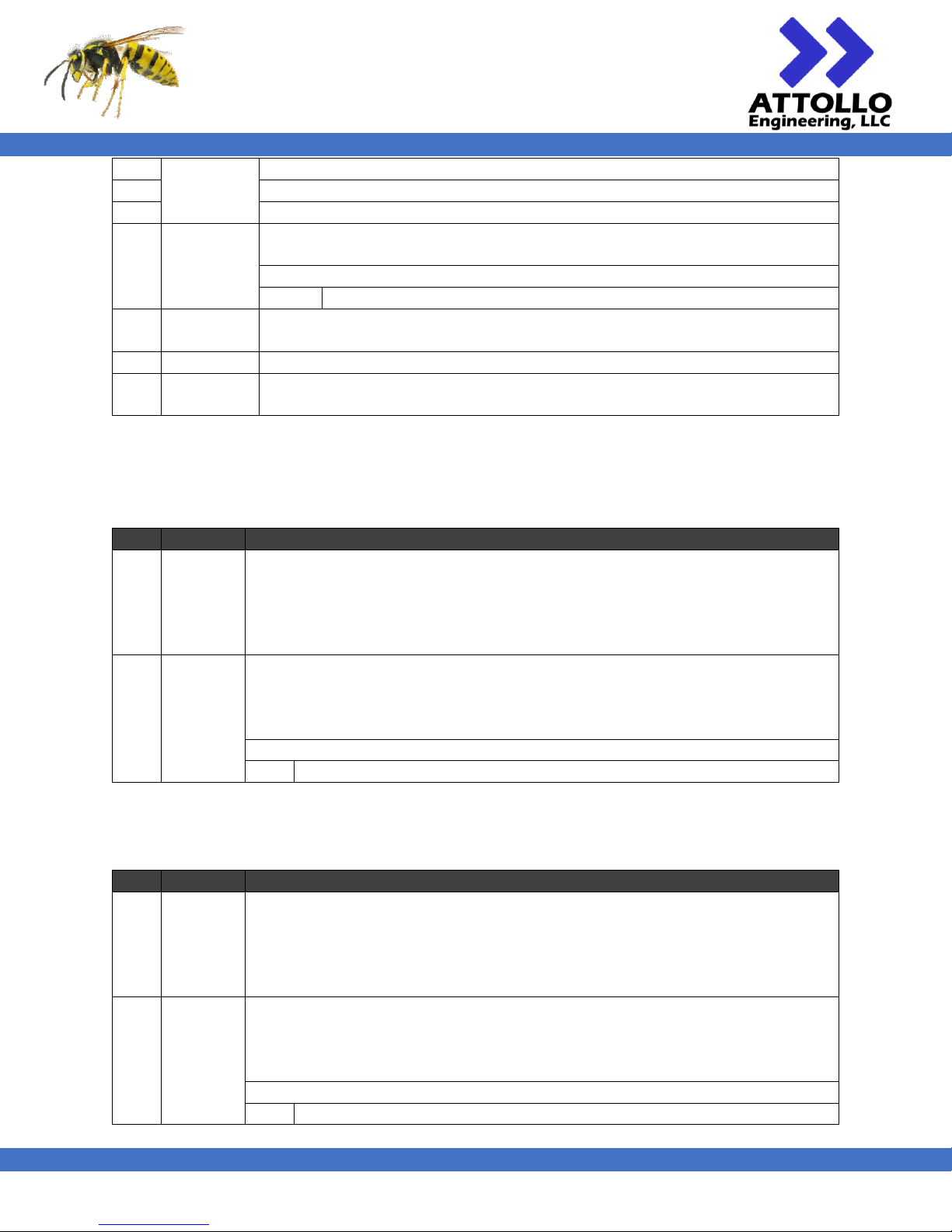
READING
Table15 - READING packet byte structure
Byte
Name
Description
0
Flags
8-bit flags
Bit 0 (MSB): Reading is bad
Bit 1: Accuracy exceeds limit – Not used; Always ‘0’
Bit 2: Reading is high resolution, else low – Not used; Always ‘0’
Bit 3: Nearest Target mode - Not used; Always ‘0’
Bit 4: Furthest Target mode - Not used; Always ‘0’
Bit 5: Max range multiplier (0 = 5 meters; 1 = 100 meters)
Bit 6: Time multiplier (0 = 50 ms; 1 = 10 ms)
Bit 7: Reserved
Page 24
WASP-200 LRF
200m Compact Laser Rangefinder
User Manual
XM000002 Rev. 004
23
1
Altitude
24-bit unsigned laser range in millimeters
2 3
4
Period
Indicates the period of the measurement, units indicated by the time multiplier
bit.
Special Cases:
0x00
Period is out of range or unknown
5
Latency
Unsigned integer; indicates the latency of the measurement. Set to ‘0x00’ as the
time from measurement to CAN message transmission is less than 1 ms.
6
Accuracy
Unsigned integer; Un-used. Set to ‘0x00'
7
Max Range
Unsigned integer; the maximum useable range of the sensor in 5’s or 100’s of
meters, depending on the state of the Max Range bit in the Flag byte.
LASER_MODE & LASER_MODE_2
This packet will set the laser’s mode. This state is remembered through a power cycle.
Table 166 – LASER_MODE packet byte structure
Byte
Name
Description
0
Flags
8-bit flags
Bit 0 (MSB): Set continuous readings on (‘1’) or off (‘0’)
Bit 1: Nearest target mode - Not used; Always ‘0’
Bit 2: Farthest target mode - Not used; Always ‘0’
Bit 3-7: Reserved
1
Period
Indicates desired period of the measurement, in 50 ms units. A value of 5, for
example will result in a measurement period of 250 ms or 4 Hz. This allows
measurement periods from 50 ms (20 Hz) to 12.75s. If longer measurement periods
are required, use the SINGLE packet to take individual readings.
Special Cases:
0xFF
No change to current period setting
In order to request range rates in excess of 20 Hz the LASER_MODE_2 packet should be used.
Table 177 – LASER_MODE_2 packet byte structure
Byte
Name
Description
0
Flags
8-bit flags
Bit 0 (MSB): Set continuous readings on (‘1’) or off (‘0’)
Bit 1: Nearest target mode - Not used; Always ‘0’
Bit 2: Farthest target mode - Not used; Always ‘0’
Bit 3-7: Reserved
1
Period
Indicates desired period of the measurement, in 10 ms units. A value of 5, for
example will result in a measurement period of 50 ms or 20 Hz. This allows
measurement periods from 10 ms (100 Hz) to 2.55s. If longer measurement periods
are required, use the SINGLE packet to take individual readings.
Special Cases:
0xFF
No change to current period setting
Page 25
WASP-200 LRF
200m Compact Laser Rangefinder
User Manual
XM000002 Rev. 004
24
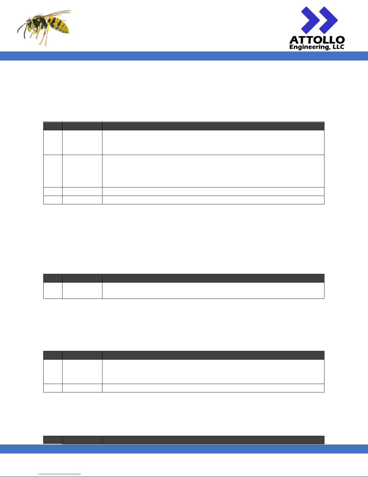
POWER & EXT_POWER
This data packet is used to turn the laser power on and off and, optionally, set the initial power-on behavior. Since this
packet has the potential to conflict with other devices on the CAN bus by using the general Piccolo uplink group (0x15), a
unique identifier has been embedded into the message to help distinguish it from others. The unique identifier is 0x1A5.
The Piccolo will periodically send this message at the appropriate phases of flight to control the on/off state of the laser.
Table 18 – POWER & EXT_POWER packets byte structure
Byte
Name
Description
0
Power Flags
8-bit flags
Bit 0 (MSB): 1: Turn Power On; 0: Turn Power Off
Bit 1-7: Reserved, set to 0
1
Behavior
Flags
8-bit flags
Bit 0 (MSB): 1: Set this message’s behavior as default power-on behavior (only
applies to Byte 0, bit 1); 0: No change
Bit 1-7: Reserved, set to 0
2
AGL ID0
0x1A (unique identifier)
3
AGL ID1
0x5E (unique identifier)
NOTE: Specific power-on behavior may be required to satisfy laser safety requirements. External interfaces used during
day-to-day operations should not alter this setting.
SINGLE
This data packet is used to request that the laser take a single measurement, using the mode settings already in memory.
If sent while the laser is in continuous mode, the unit will return an extra measurement between the normal period, if
time allows, and then resume the continuous readings.
Table 19 – SINGLE packet byte structure
Byte
Name
Description
0
Request
‘0x05’ – Requests the AGL sensor to take a reading and return a single READING
packet
UPDATE_OFFSET
This data packet is used to update the unit’s unique, manufacturer specified laser offset value. As this value is supplied by
the manufacturer and calibrated at the factory, this packet is not intended to be used by the end user.
Table 20 – UPDATE_OFFSET packet byte structure
Byte
Name
Description
0
OFFSET_0
1st byte of the unsigned 16-bit integer representing the factory calibrated offset
in millimeters which is added to the laser measurements. This offset is a product
of the calibration process and is unique to the laser within each unit.
1
OFFSET_1
2nd byte of the aforementioned unsigned 16-bit integer.
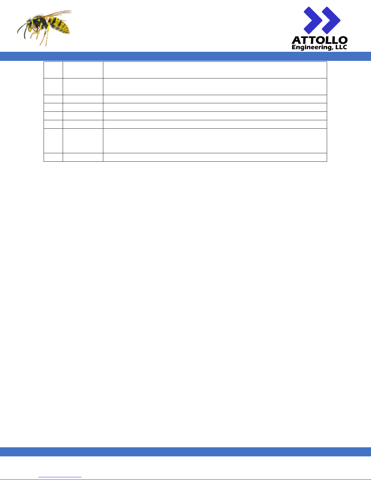
DATE_VERSION
This packet sends the firmware version, build date, and the hardcoded offset.
Table 21 – DATE_VERSION packet byte structure
Byte
Name
Description
Page 26
WASP-200 LRF
200m Compact Laser Rangefinder
User Manual
XM000002 Rev. 004
25
0
Major
Version
The 1 in 1.2.3
1
Minor
Version
The 2 in 1.2.3
2
Sub Version
The 3 in 1.2.3
3
Date month
4 Date day
5 Date year
For 2018, the value will be 18
6
OFFSET_0
1st byte of the unsigned 16-bit integer representing the factory calibrated offset
in millimeters which is added to the laser measurements. This offset is a product
of the calibration process and is unique to the laser within each unit.
7
OFFSET_1
2nd byte of the aforementioned unsigned 16-bit integer.
The DATE_VERSION packet can be requested by sending a packet with the DATE_VERSION packet type, a size byte of 0,
and no data bytes.
RS-232 Commands
The RS-232 interface is used to access the rangefinder settings and parameters associated with the WASP-200 MC1 with
the use of the “LRF” command.
LRF
This command sends an LRF command, according to those listed the Serial Commands section of this manual. The user
may use the LRF command to set the number of averages, set the median filter window size, etc. which will be utilized
when requesting range information via the CAN interface.
The following commands should not be used in conjunction with the LRF command as they may cause the MC1-001 to
stop communicating properly:
FMT
BAUD
CHK
TRG
An example of usage of the LRF command is:
>LRF SET
< THR220 TOS0 OFS0 FRQ4 VLT698 AVG1 MVG1 AUT1 AUV1 MDF1 LBE|BIG FMT|ASCII CHK0 TRG0 SAV1
Use with Cloud Cap Piccolo Autopilot
Simply install the MC1-001 LRF. The default settings enable the CAN message output in continuous mode, which will be
recognized and utilized by the Piccolo with no additional settings necessary.
Page 27
WASP-200 LRF
200m Compact Laser Rangefinder
User Manual
XM000002 Rev. 004
26
Revision History
Version
Date
Comments
001
2018-05-16
Initial version
002
2018-10-15
FDA Laser Compliance approval updates
003
2018-11-21
Update to version command formatting, RANGE_NOT_READY error code added.
Added CHKSUM and TRIG commands.
Note in introduction regarding 10 kHz only applying to Class 3 operation. Not available in
Class 1 product.
004
2018-12-20
Combining Commercial Version with CAN Bus Version into One User Manual
Added commands associated with 18500001 Firmware Update.
005
2018-12-21
Made TLA command deprecation consistent throughout documentation
Corrected examples
Added LOM command
 Loading...