

Page 1
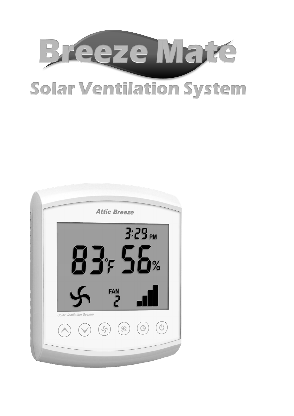
User Manual
For use with model CS-10D/CS-11D
solar ventilation system controllers
TM
Page 2
Breeze Mate™ Solar Ventilation System
Thank you for your purchase of the Breeze Mate™ solar
ventilation system by Attic Breeze. Our advanced control
system offers full control over the operation of your Attic
Breeze solar powered ventilation products, as well as many
safety and performance related features. Please read this
user manual in its entirety before proceeding with your
installation and take time to become familiar with the
Breeze Mate™ control system.
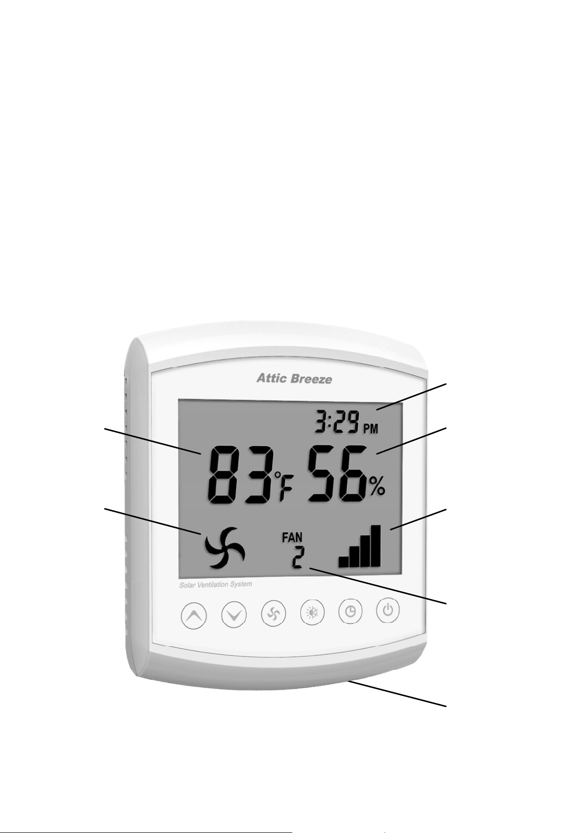
MC-10A Remote Interface Controller
1
2
13
12
11
10
3 4 5 6 7 8
-2-
9
Page 3

Temperature Display
1
May be configured for display in either °F or °C. Reports attic
air temperature over a range of 16°F - 176°F (-9°C - 80°C).
Fan Icon
2
Displays when fan is operating.
3
Increase Button
Used for adjustments to controller settings. Holding down the
increase button for 10 seconds will access the controller
Configuration Menu.
Decrease Button
4
Used for adjustments to controller settings. Holding down the
decrease button for 10 seconds will access the controller
Depressurization Test Menu.
Fan Button
5
Used to switch between network channels when more than
one FC-10A Fan Controller is installed on the network.
6
7
8
9
10
11
Temperature/Humidity Control Button
Used to access Temperature/Humidity Control Menu. Also
used to acknowledge changes to controller settings.
Clock Button
Used for adjustments to clock settings. Holding down the
clock button for 10 seconds will access Clock Menu.
On/Off Button
Used to manually control operation of fan (on/off).
Battery Access Panel
Push in panel to access battery compartment. Requires two
(2) AAA batteries.
Fan Controller Channel Display
Displays selected network communication channel.
Power Indicator Bars
Displays amount of power available to operate fan.
-3-
Page 4
MC-10A (continued)
12
13
Humidity Display
Reports relative humidity conditions over a range of 1-99%.
Clock Display
May be configured for either 12 hour or 24 hour time mode.
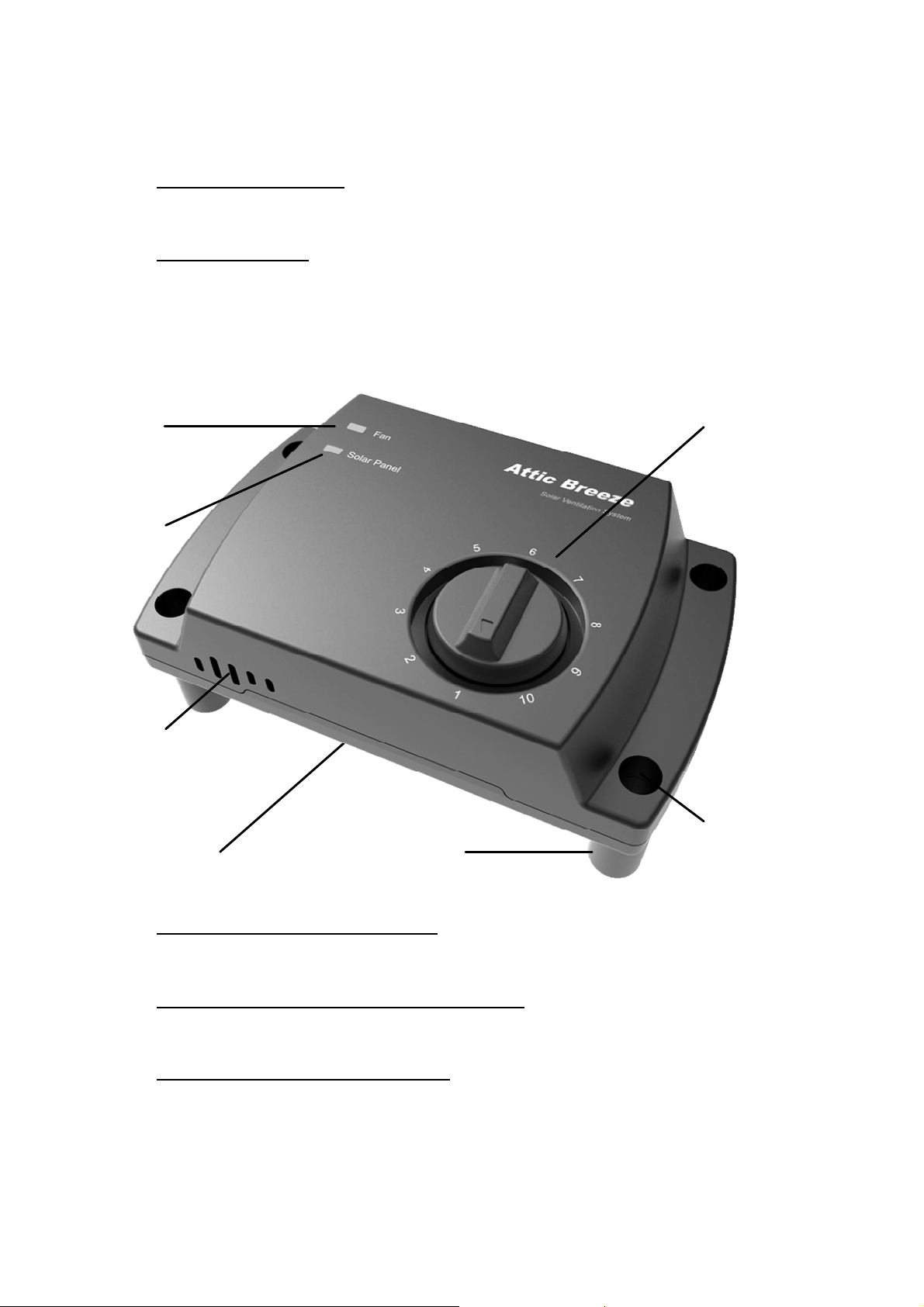
FC-10A Fan Controller
14
15
20
16
14
15
16
19
17 18
Fan Power LED Indicator
Displays when controller sends power to fan.
Solar Panel Power LED Indicator
Displays when power is available from solar panel.
Fusible Link Safety Switch
Stops operation of fan in the event of a fire.
-4-
Page 5
17
Plug Connectors
Used to connect controller to with WH-10A/WH-10D
Communication Cable (bottom of controller).
18
19
20
Mounting Posts
Offset mounting posts allow for accurate sensing of air
temperature and humidity by minimizing contact of the
controller with attic framing members.
Mounting Holes
Design to fit #8 wood screws (included with controller).
Network Channel Selector
Used to assign a unique wireless network address to the fan
controller. Network designed to accommodate up to 10 fan
controllers.
Getting Started
The Breeze Mate™ solar ventilation system is designed for
easy installation and configuration. However, if you require
assistance, Attic Breeze is here to help.
Customer Support
Monday - Friday 8:30AM - 5:30PM CST
254-865-9999
The Breeze Mate™ CS-10D and CS-11D control
!
systems are designed for use with Attic Breeze
model solar attic fans featuring a remote mounted
solar panel. If your Attic Breeze fan features a
unit mounted solar panel, the CS-10A or CS-11A
control system is appropriate for your installation.
Contact Attic Breeze customer support for more
information or consult your local Attic Breeze dealer
for additional assistance.
-5-
Page 6
FC-10A Installation
►
►
!
Begin by locating the WH-10D Communication Cable
included with your control system. The WH-10D cable
features a 2-plug connector on each end of the cable
designed to connect with your Attic Breeze model fan.
Next, locate the 2-plug connector power cable on your
Attic Breeze fan. The power cable should be hanging
freely from the bottom of the fan. If necessary, unplug
the solar panel power cable if the product has already
been in use. Plug the WH-10D Communication Cable
into the fan’s power cable and route the WH-10D
cable to the location where the FC-10A Fan Controller
will be installed. Secure the WH-10D Communication
Cable as needed.
If your Attic Breeze model fan is equipped with a
thermal switch, the switch must be removed
►
before using the Breeze Mate™ CS-10D/CS-11D
control systems. For newer model fans, simply
unplug the thermal switch and plug in the termination
plug that came with your fan. On older Attic Breeze
model fans, you must remove the switch and complete
the circuit. For more information, contact customer
support or consult your local Attic Breeze dealer.
The FC-10A Fan Controller should be installed within
roughly 5-6 feet of your Attic Breeze fan. Choose an
unrestricted, open location that allows the controller
proper access for monitoring of attic air conditions.
Using the included #8 wood screws, mount the
FC-10A Fan Controller on a vertical framing member
or wall mounting surface. The controller should be
mounted with the Fusible Link Safety Switch [16] vent
facing downward, toward the attic floor. Do not over
tighten the mounting screws during installation.
-6-
Page 7
►
!
Locate the Plug Connector [17] on the FC-10A Fan
Controller labeled Power In and connect it with the
2-plug connector on the solar panel power cable.
Next, plug the WH-10D Communication Cable into the
Plug Connector [17] labeled Power Out.
If the solar panel on your Attic Breeze fan is
exposed to sunlight, the Solar Panel Power LED
Indicator [15] on the FC-10A Fan Controller will be
illuminated. If the LED indicator is not illuminated,
verify that the plug connectors are properly matched
and secured.
►
Using the Network Channel Selector [20], assign the
next available wireless network channel address to the
FC-10A Fan Controller. If this is the first controller
installed, set the selector dial to channel one.
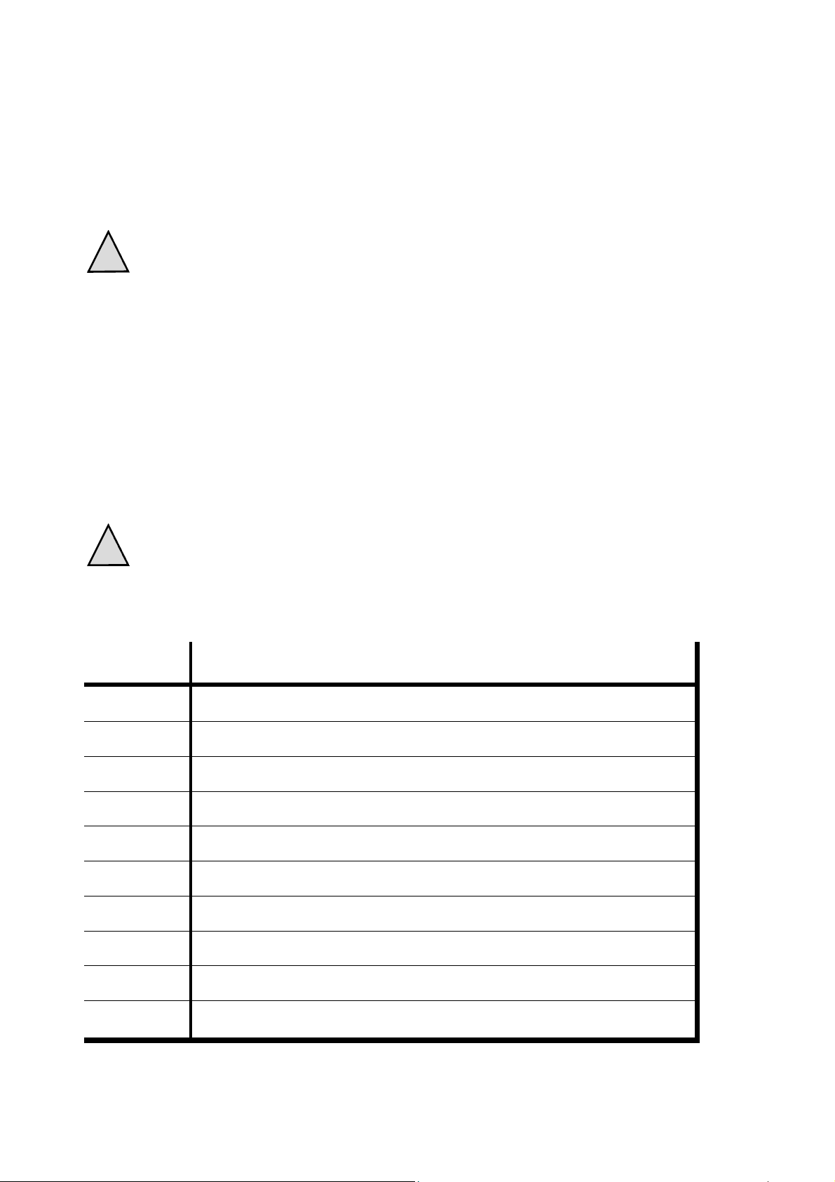
Each installed FC-10A Fan Controller must be
!
assigned a unique wireless network channel
address for proper operation.
Channel Fan Controller Location
1
2
3
4
5
6
7
8
9
10
-7-
Page 8
MC-10A Installation
►
►
Locate the Battery Access Panel [9] on your MC-10A
Remote Interface Controller. Push the panel to
access the battery compartment and install the two (2)
AAA batteries included with your control system.
Access the controller Configuration Menu by holding
down the Increase Button [3] for 10 seconds.
21
22
21
22
23
►
23
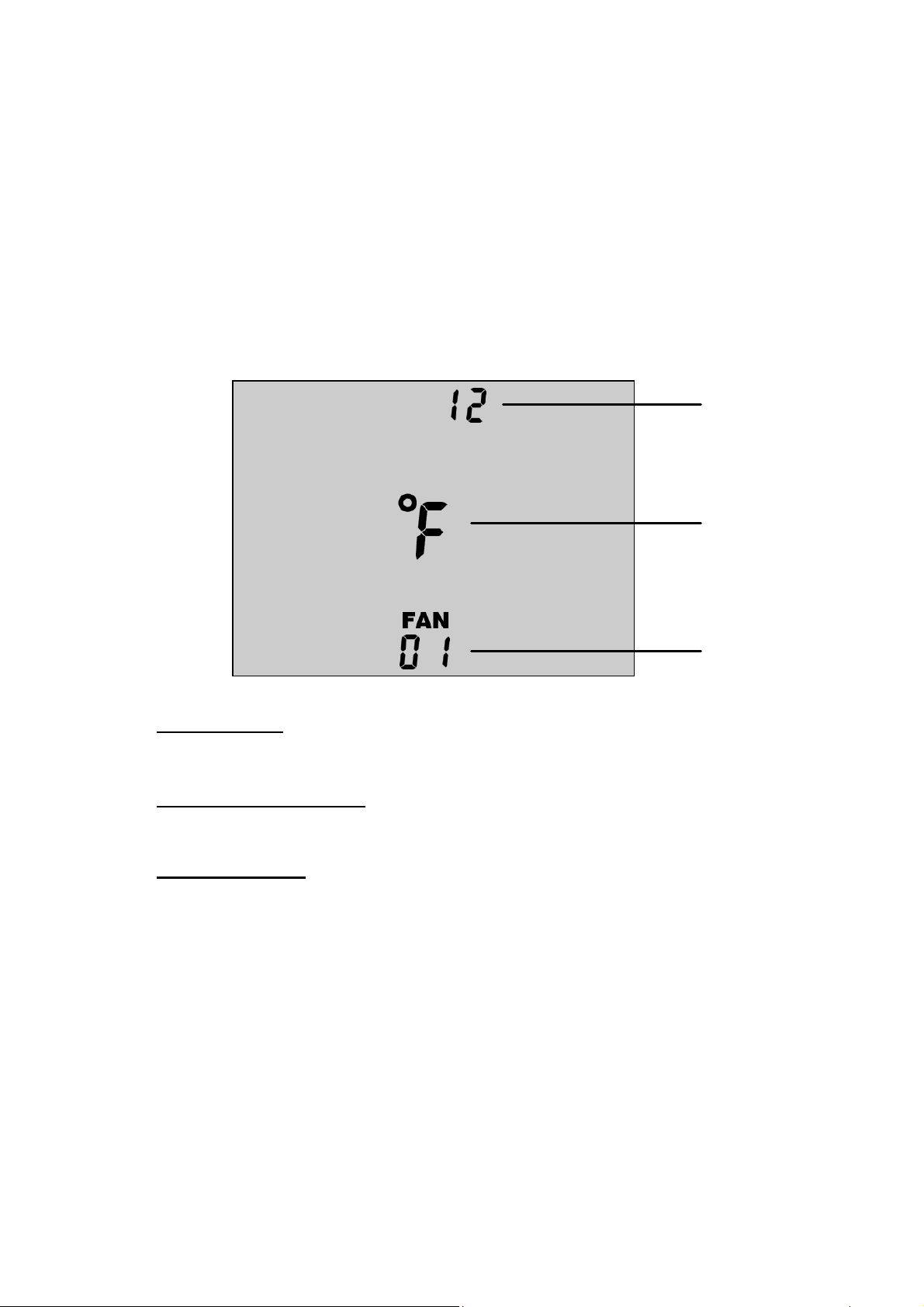
Time Mode
Choose either 12 hour or 24 hour time mode for clock.
Temperature Units
Choose either °F or °C for temperature display.
Network Size
Select the number of fan controllers installed on the network.
While in the Configuration Menu, use the Increase
Button [3] and Decrease Button [4] to make your menu
selections. The parameter to be configured will blink
until your selection is acknowledged. Using the
Temperature/Humidity Control Button [6],
acknowledge your selection and proceed to the next
configuration parameter.
-8-
Page 9
►
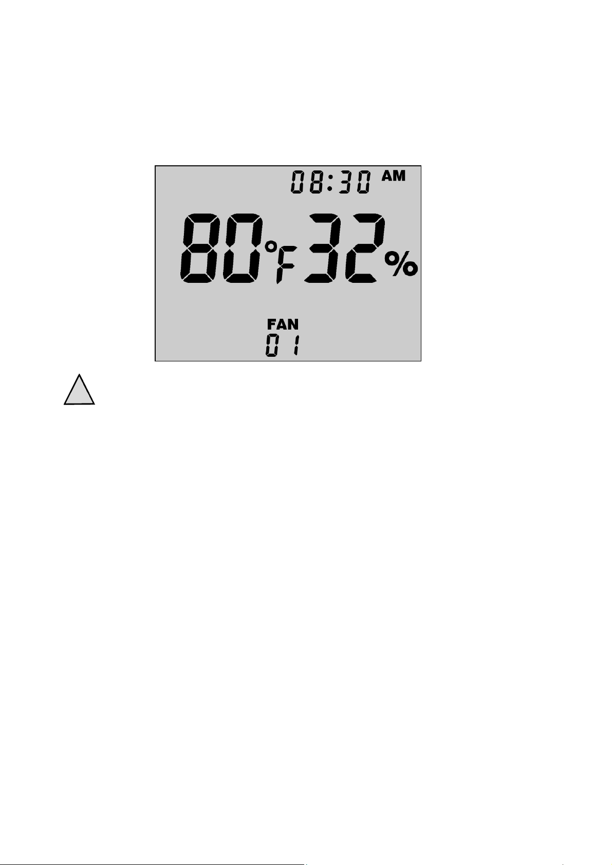
With the MC-10A controller configured to the desired
settings, the display screen should now show the
current temperature and relative humidity for the fan
controller assigned to network channel one.
!
►
Temperature Display [1] and Humidity Display [12]
will show “- -” on the display screen whenever the
MC-10A Remote Interface Controller is not able to
establish communication with a fan controller on
the wireless network. This will normally occur when
there is not enough sunlight for fan operation.
However, lack of communication may also occur when
there is too much interference or distance between the
MC-10A controller and a specific fan controller.
Using the Fan Button [5], cycle through the controller
network channels and verify that all installed fan
controllers on the wireless network are in
communication with the MC-10A Remote Interface
Controller. If needed, repeat this procedure in the
location where the MC-10A controller will be installed.
►
Mount the MC-10A Remote Interface Controller in your
desired location. Slide-on screw mounts are provide
on the controller housing for your convenience.
-9-
Page 10
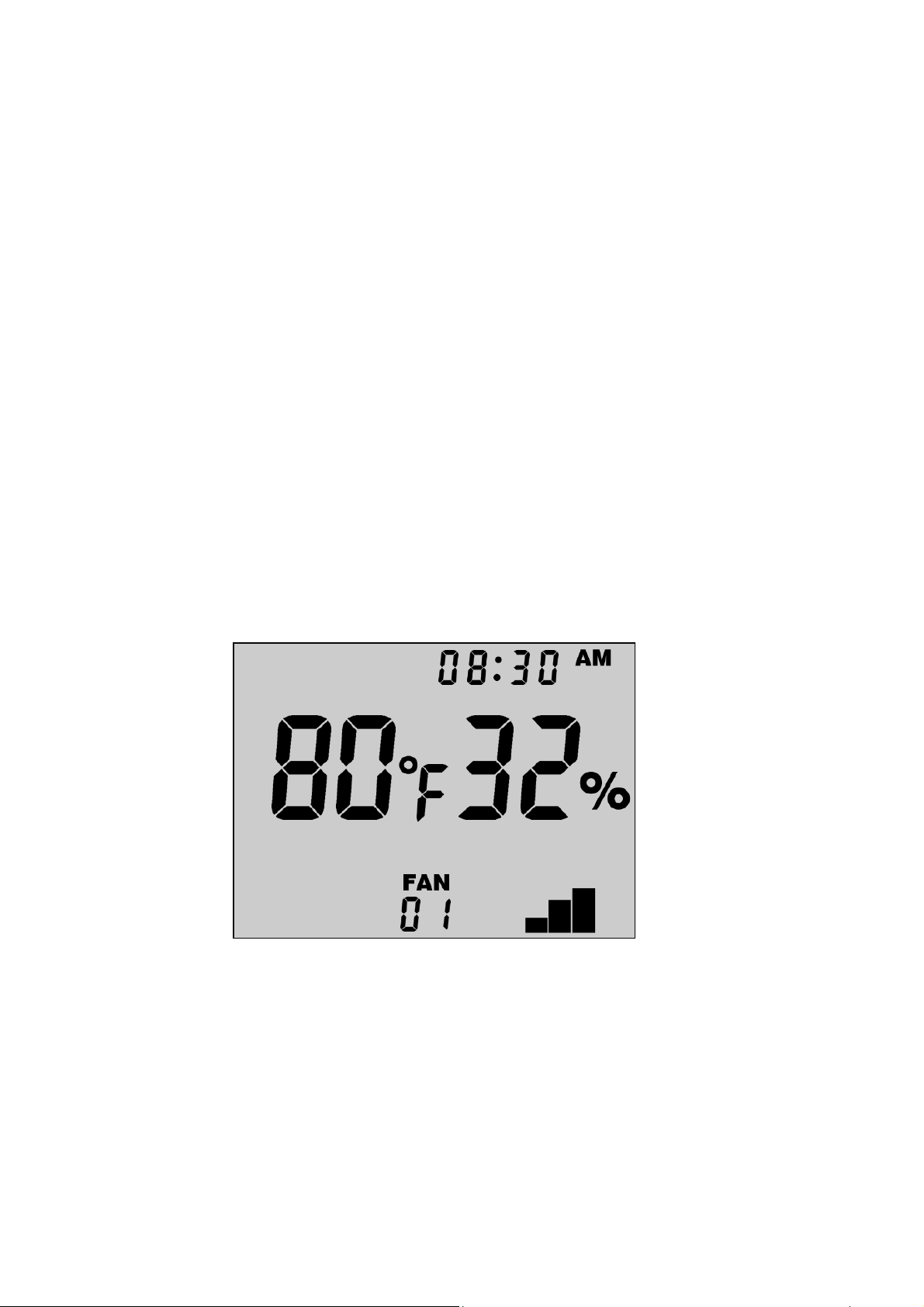
Automatic Control Mode
By default, all fans on the Breeze Mate™ control system
network are set to automatic mode off when first installed.
Fans may be configured for automatic mode operation
either individually if needed, or all at the same time using
the network’s global update channel.
►
►
Using the Fan Button [5], select the desired fan
controller to configure for automatic operation. To
configure all installed fan controllers on the network,
select the global update channel “AL”.
Press the On/Off Button [8] to switch the fan controller
to automatic mode on. When configured for automatic
operation, the MC-10A Remote Interface Controller
will display the Power Indicator Bars [11] to show the
amount of solar power available for fan operation.
►
Likewise, any single fan or all fans on the network may
be manually turned off by simply following the same
procedure above. While in automatic mode off, a fan
controller will continue to update the MC-10A Remote
Interface Controller with temperature and humidity
data, but the fan will not be allowed to operate.
-10-
Page 11
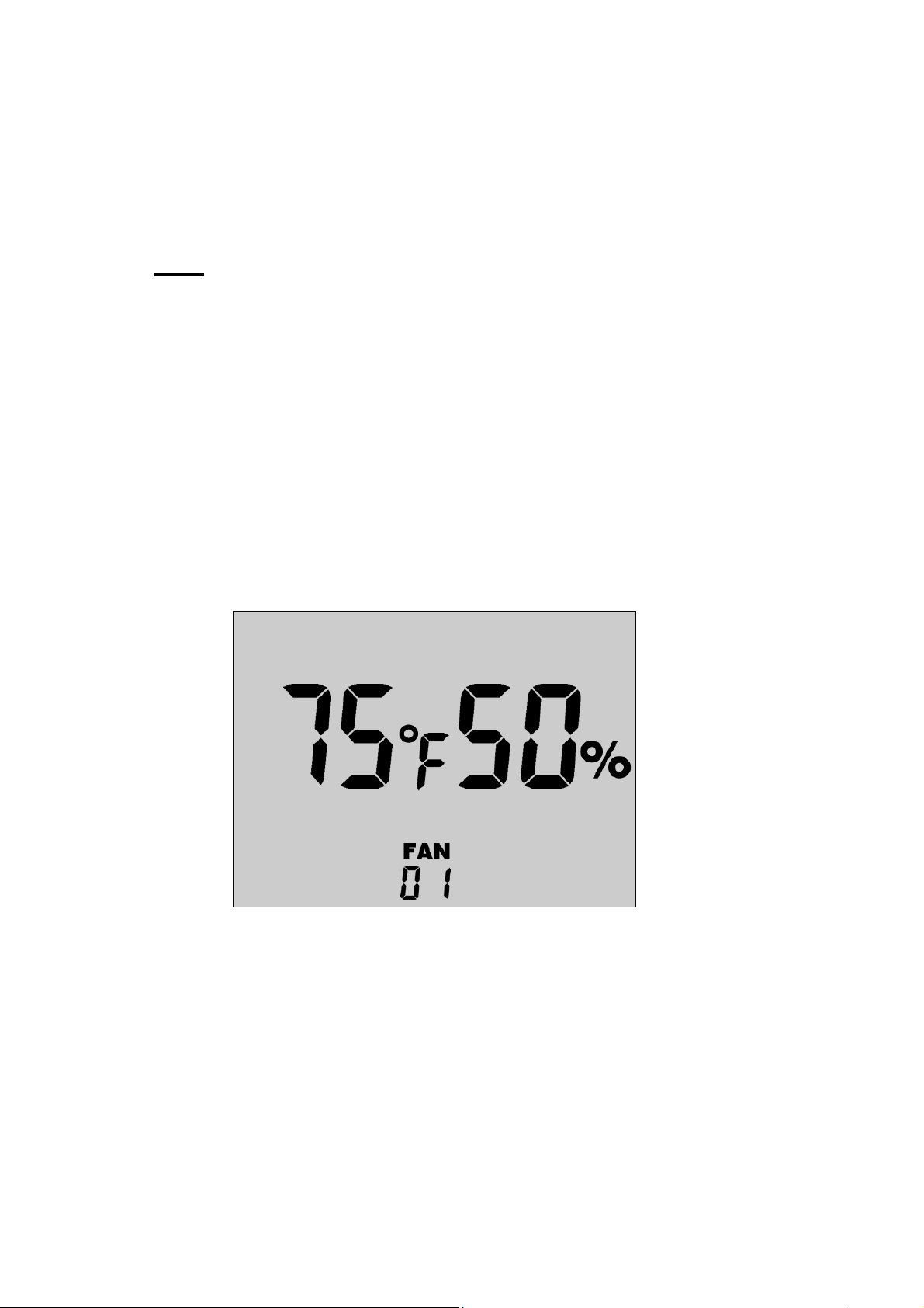
Adjusting Temperature & Humidity
The Breeze Mate™ control system offers independent
control of both temperature and humidity. Based on the
control set points selected, your fan will continue operation
until both the temperature and humidity set point targets
are satisfied. Temperature and humidity set points may be
adjusted for each fan controller individually, or all at the
same time using the network’s global update channel.
►
►
Using the Fan Button [5], select the desired fan
controller for temperature and humidity set point
adjustment. To configure all installed fan controllers
on the network, select the global update channel “AL”.
Access the Temperature/Humidity Control Menu by
pressing the Temperature/Humidity Control Button [6].
►
While in the Temperature/Humidity Control Menu,
use the Increase Button [3] and Decrease Button [4] to
make your adjustments. The temperature set point
will blink until the change is acknowledged by pressing
the Temperature/Humidity Control Button [6]. Next,
make your adjustments to the humidity set point and
acknowledge changes to exit the menu.
-11-
Page 12
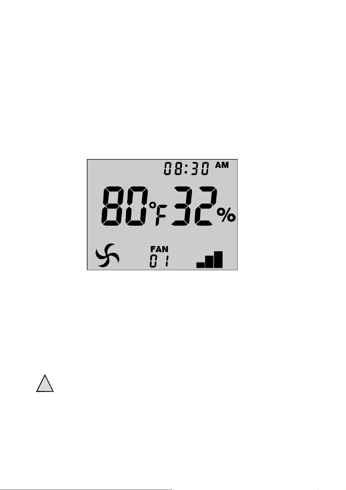
Operating the Control System
The Fan Icon [2] is used to indicate when a selected Attic
Breeze fan is operating. While in automatic control mode,
the MC-10A controller will display the Fan Icon [2] and
make a selected fan operational any time either the current
temperature or humidity are greater than the controller’s set
points. Additionally, the Fan Power LED Indicator [14] on
the FC-10A Fan Controller will be illuminated when the
selected fan is operating.
Operation of your Attic Breeze fan may be configured within
the below set point ranges:
Temperature 32F° - 122°F (0°C - 50°C)
Humidity 10% - 90%
For optimum energy efficiency, Attic Breeze recommends a
temperature set point of 75°F (24°C) and a humidity set
point of 50% for typical attic ventilation applications.
Set point changes and configuration settings will
!
remain in memory when the fan controller shuts
down at night. When enough sunlight is available,
the FC-10A Fan Controller will re-establish
communications and resume operation as normal.
-12-
Page 13
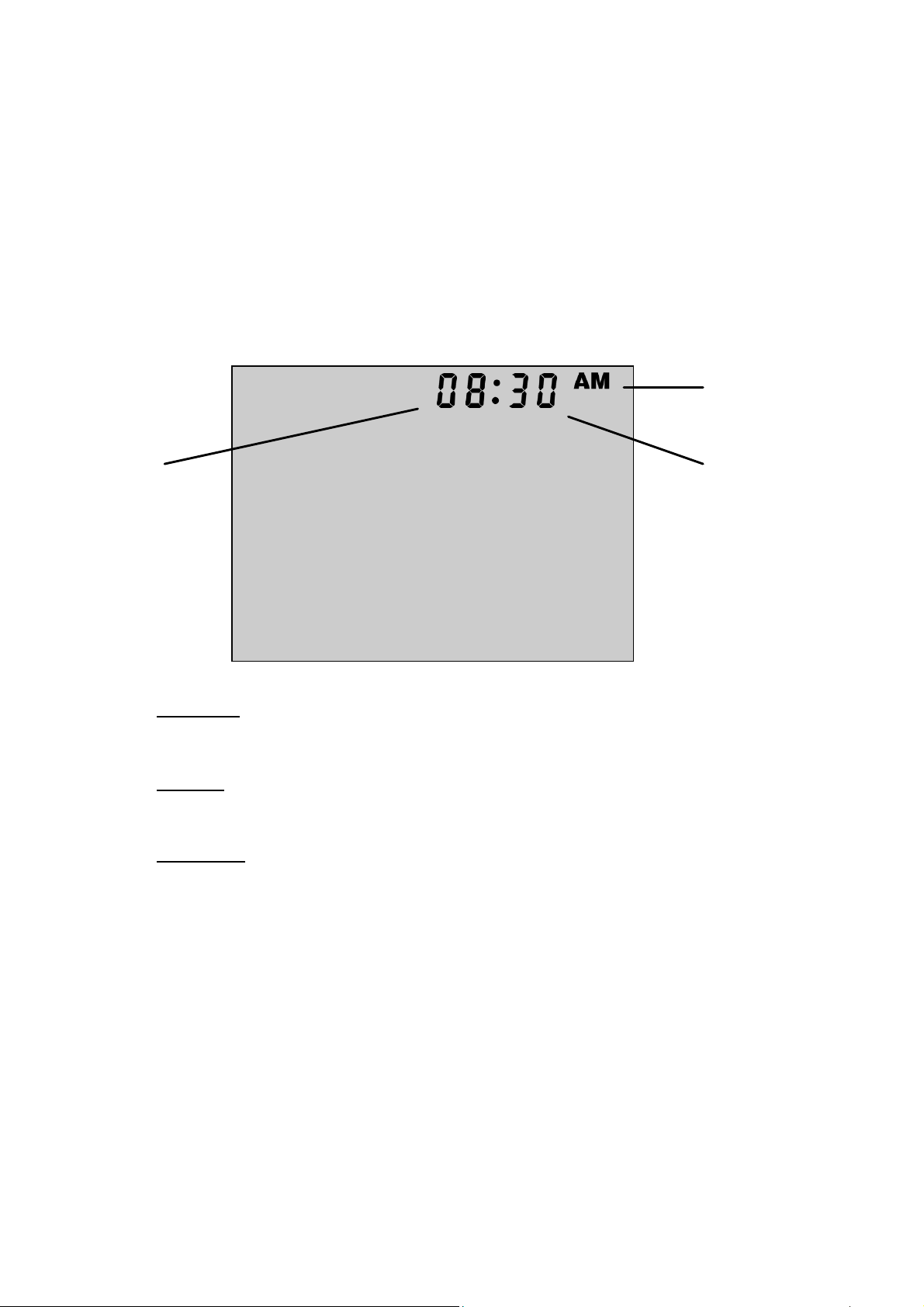
Setting the Clock
The MC-10A Remote Interface Controller features an
electronic clock for your convenience. The clock may be
configured for either 12 hour or 24 hour time mode display.
►
25
24
Access the Clock Menu by holding down the Clock
Button [7] for 10 seconds.
24
26
AM/PM
If configured for 12 hour time mode, select either AM or PM.
25
26
►
Hours
Select the current hour.
Minutes
Select the current minute.
While in the Clock Menu, use the Increase Button [3]
and Decrease Button [4] to make your menu
selections. The parameter to be configured will blink
until your selection is acknowledged. Using the Clock
Button [7], acknowledge your selection and proceed to
the next parameter.
-13-
Page 14
Testing for Attic Depressurization
The Breeze Mate™ solar ventilation system features our
proprietary differential pressure sensing technology
designed to prevent attic depressurization. When an attic
space has insufficient intake ventilation, depressurization of
the attic may occur resulting in decreased energy efficiency
and poor performance from your solar attic fan. Breeze
Mate™ gives you the control to ensure that your solar attic
fan is properly installed and operating at maximum air flow
performance.
►
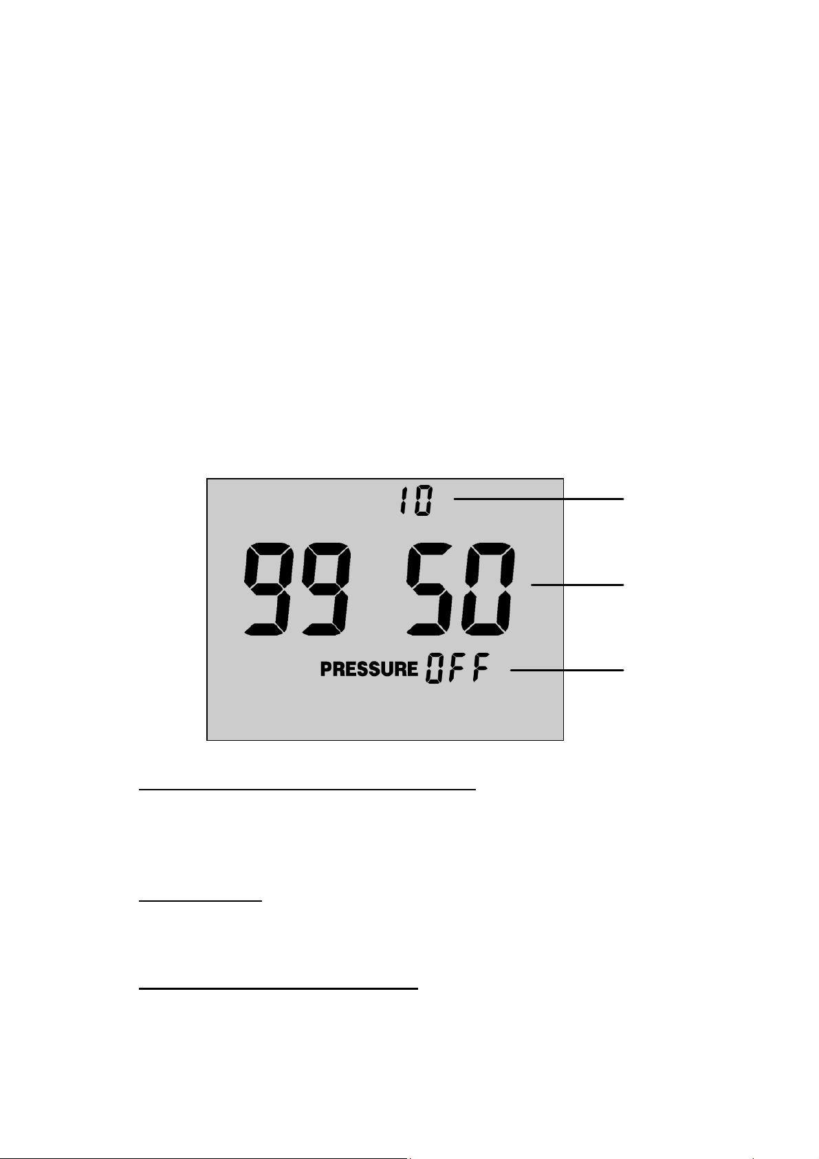
27
Access the Depressurization Test Menu by holding
down the Decrease Button [4] for 10 seconds.
27
28
29
Depressurization Alarm Threshold
The depressurization alarm threshold sets the not-to-exceed
value for depressurization testing. This parameter may be
adjusted within the range of 0-10 pressure units (Pa x 10).
28
29
Air Pressure
Displays the current air pressure in units of Pa x 10.
(ex. 9950 Pa x 10 = 99,500 Pa = 995 mbar = 29.4 inHg)
Depressurization Test Mode
Select “on” to start the depressurization test.
-14-
Page 15
►
!
While in the Depressurization Test Menu, use the
Increase Button [3] and Decrease Button [4] to make
your menu selections. The parameter to be
configured will blink until your selection is
acknowledged. Using the Temperature/Humidity
Control Button [6], acknowledge your selection and
proceed to the next parameter.
For optimum fan performance, Attic Breeze
recommends beginning with a Depressurization
Alarm Threshold [27] setting of “2” pressure units.
This alarm setting will ensure that your Attic Breeze
solar attic fan is supplied with sufficient air intake
ventilation to operate at maximum performance.
►
!
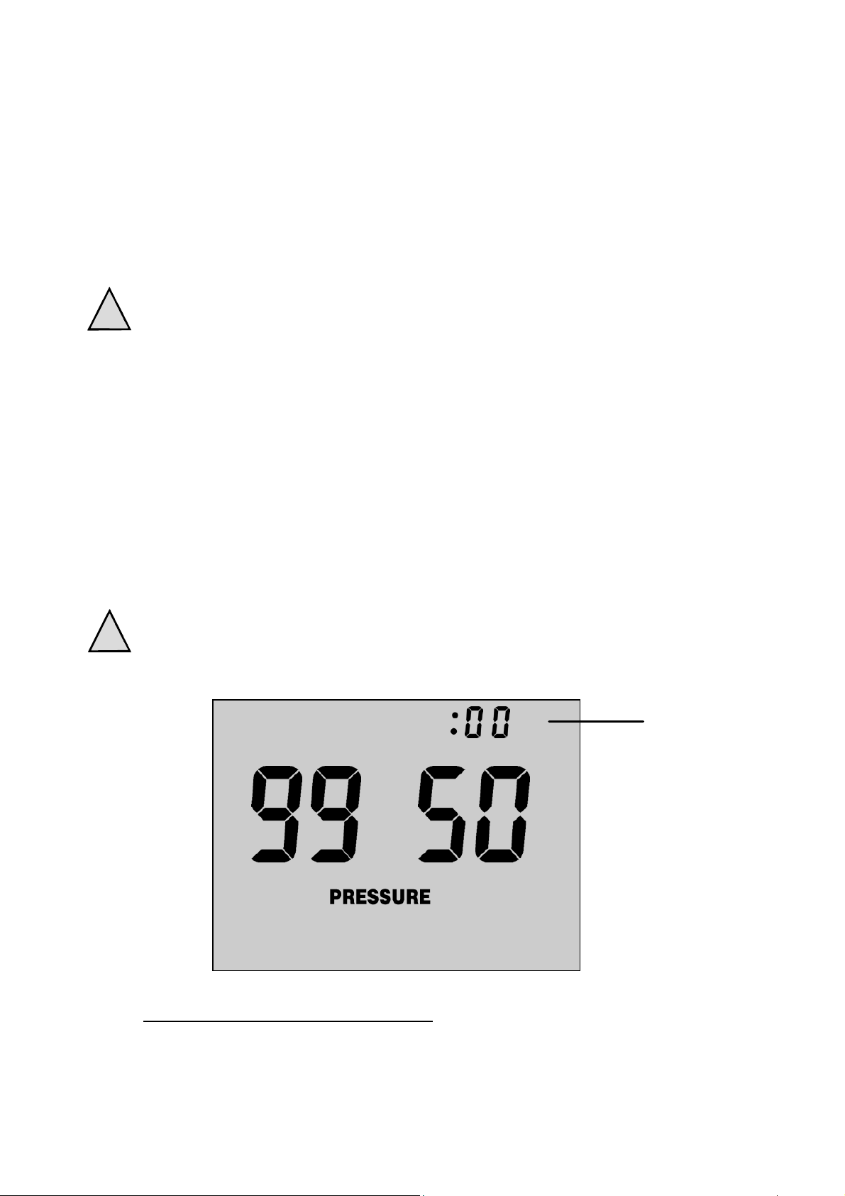
When the Depressurization Test is started, the Breeze
Mate™ control system will shut down all fans installed
on the network for a period of five minutes, allowing
the attic pressure to come to equilibrium with ambient
barometric pressure.
The Depressurization Test may be stopped at any
time by pressing the On/Off Button [8].
30
30
Depressurization Test Timer
Displays time elapsed during depressurization testing.
-15-
Page 16
Depressurization Testing (continued)
►
!
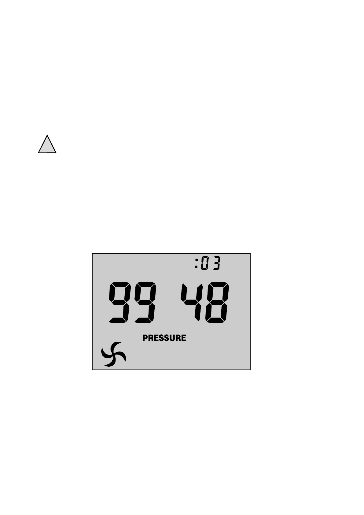
At the end of the equilibrium period, the Breeze
Mate™ control system will collect pressure data to
establish a barometric pressure baseline. After this
data is collected, the control system then starts all fans
installed on the network, allowing the fans to operate
for a period of five minutes.
Expect slight changes in the ambient barometric
pressure readings, even when your solar attic fan
is not operating. Due to the extreme sensitivity
designed into our pressure sensing technology,
normal variations in the barometric pressure will be
observed during testing. For this reason, Attic Breeze
recommends performing the Depressurization Test
during clear and sunny weather conditions to minimize
interference from changes in barometric pressure.
►
At the end of this period, the control system once
again collects pressure data. The values recorded for
attic pressure, both during fan operation and without,
are compared to determine the amount of attic
depressurization present. The result is then evaluated
to determine the final status of the test.
-16-
Page 17
►
!
If your solar attic fan installation passes the
Depressurization Test, the controller will exit the test
program after 10 seconds and return to the main
display screen. A “passed” test indicates that your
attic has the proper amount of intake ventilation to
support your ventilation system.
Please note that the Breeze Mate™ control system
defaults to automatic mode off upon exit of the
Depressurization Test. Automatic control must be
turned on after testing to resume temperature and
humidity control.
►
!
If your solar attic fan installation does not pass the
Depressurization Test, the Fan Icon [2] will begin
blinking and the controller will remain in alarm mode
until the depressurization alarm is acknowledged. The
depressurization alarm may be acknowledged by
pressing the On/Off Button [8]. A “failed” test indicates
that your attic may not have the proper amount of
intake ventilation to support your ventilation system.
If your installation fails the Depressurization Test,
check the following:
Run the test again to confirm the results.
Changes in barometric pressure may effect
testing, resulting in a “borderline” test failure.
Verify that the Depressurization Alarm
Threshold [27] value is set properly. If the
alarm is set too low, atmospheric pressure
interference may adversely effect testing.
Make sure your soffits and other air intake
vents are clear of debris and obstructions.
If needed, repeat the test using the next
highest Depressurization Alarm Threshold [27]
setting. A “passed” test at higher settings may
indicate the need for more air intake ventilation.
-17-
Page 18

Technical Information
Temperature Sensor Range
absolute accuracy
resolution
Temperature Control Range 32°F - 122°F (0°C - 50°C)
deadband 4°F (2°C)
Relative Humidity Sensor Range 1% - 99%
absolute accuracy
resolution
Relative Humidity Control Range 10% - 90%
deadband 4%
Barometric Pressure Sensor Range 30,000 Pa - 110,000 Pa
relative accuracy 20 Pa
16°F - 176°F (-9°C - 80°C)
1.8°F (1.0°C)
0.4°F (0.2°C)
3%
0.1%
resolution 1 Pa
Controller Update Interval 10 min
Two Year Product Warranty
Your new Breeze Mate™ solar ventilation system is
warranted by Attic Breeze, LLC, to be free from defects in
material and workmanship under normal use for two (2)
years from the date of purchase. This warranty shall not
cover damage caused by improper use, abuse, accidents,
alterations to the product, nor does it cover damage
resulting from installation of the product or service
performed on the product by persons other than Attic
Breeze. This warranty is limited to the original purchaser
only. Warranties must be registered through our online
warranty registration system within 90 days of purchase.
Please visit our website (www.atticbreeze.net) for details.
-18-
Page 19

Customer Support
Have questions or comments about our products? Attic
Breeze Customer Support is available Monday - Friday,
8:30AM - 5:30PM CST. For quick assistance, please be
prepared with the following information:
Attic Breeze fan model number
When the Attic Breeze fan was installed
Dealer/Installer
Breeze Mate™ control system model number
254-865-9999
www.atticbreeze.net
Thank you for choosing Attic Breeze!
Breeze Mate™ is a trademark of Attic Breeze, LLC. All
rights reserved.
-19-
Page 20

www.atticbreeze.net
Rev. 0.1 Copyright © 2012 Attic Breeze, LLC. All rights reserved.
 Loading...