

Page 1
Hardware
Guide
Shadow Tracker
Premier
TM
Advanced Tracking Technologies Inc.
© 2002 ATTI All rights reserved
TM
Page 2

Manual Number: M-2869
Copyright © 2002, Advanced Tracking Technologies, Inc.
All rights reserved. No part of this publication may be reproduced or
transmitted in any form or by any means without the prior written
permission of Advanced Tracking Technologies, Inc.
ATTI, Advanced Tracking Technologies, Shadow Tracker, MobilEyes
and Time Traveler are trademarks of Advanced Tracking
Technologies, Inc.,
Microsoft, Windows and the Windows logo are registered trademarks
of the Microsoft Corporation.
Pentium is the registered trademark of Intel Corporation. Other
brands and products are trademarks of their prospective holders.
www.Advantrack.com
Page 3

Federal Communications Commission (FCC) Notification
This device complies with part 15 of the FCC rules. Operation is subject
to the following two conditions:
1. This device may not cause harmful interference.
2. This device must accept any interference received, including
interference that may cause undesired operation.
This equipment has been tested and found to comply with the limits for a
Class A digital device, pursuant to part 15 of the FCC Rules. These limits
are designed to provide reasonable protection against harmful interference
when the equipment operates in a commercial environment. Properly
shielded and grounded cables and connectors must be used in order to
meet FCC emission limits.
This equipment generates, uses, and can radiate radio frequency energy
and, if not installed and used in accordance with the instruction manual,
may cause harmful interference to radio communications.
Operation of this equipment in a residential area is likely to cause harmful
interference in which case the user will be required to correct the
interference at his own expense.
Only peripherals certified to comply with the Class A limits may be attached
to this device. Operation with non-certified peripherals or peripherals not
recommended by Advanced Tracking Technologies, Inc. is likely to result
in interference to radio and television reception.
Unauthorized changes or modifications could void the user's authority to
operate the equipment.
This device must be operated as supplied by Advanced Tracking
Technologies, Inc.. Any changes or modifications made to the device
without the express written approval of Advanced Tracking Technologies,
Inc. may void the user's authority to operate the device.
Advanced Tracking Technologies, Inc. is not responsible for any radio or
television interference caused by using other than recommended cables
and connectors or by unauthorized changes or modifications to this
equipment.
CAUTION: The Shadow Tracker Premier has maximum
transmitted output power of 200mW. It is required that the
transmit antenna (located inside the Shadow Tracker™ Premier)
be kept at least 23 cm away from nearby persons to satisfy FCC
RF exposure requirements.
Page 4

Page 5

TABLE OF CONTENTS
Introduction to MobilEyes 1
Connecting the Unit
Mounting and Placement
Connecting Power
Wiring Instructions
Status Indicator Lights
GPS Antenna
Removing the Unit for Download
Other Information 6
Safety and Care Instructions 7
Specifications of Shadow Tracker Premier 8
Trouble Shooting 9
™
™
3
3
4
4
5
5
TC
Page 6
INTRODUCTION
Please read this manual completely before use.
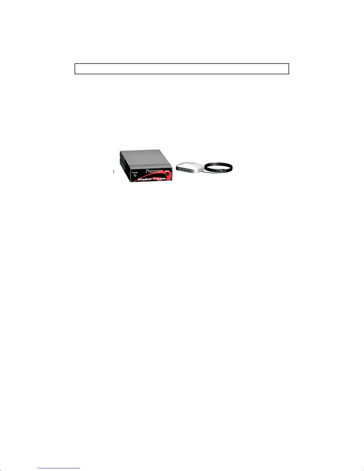
Thank you for purchasing Shadow Tracker™, the cornerstone of the MobilEyes
vehicle tracking system from
MobilEyes is a unique hardware and software combination, used for the
tracking needs of today’s mobile workforce.
The Shadow Tracker™ Premier uses a stationary system of satellites placed
around the globe in orbit by the Department of Defense (DOD). Signals received
from one satellite are compared to signals of three others in view. The small
differences in reception can be used to calculate the position anywhere on the
Earth through triangulation.
™
Advanced Tracking Technologies, Incorporated.
Shadow Tracker Premier™
™
1
Page 7

INTRODUCTION
The Shadow Tracker™ Premier easily installs into a vehicle and use the vehicles
electrical system. The unit gathers and stores vital GPS data which is
downloaded into the application software providing detailed distance, location
and time information necessary for accurately monitoring your mobile staff.
Although rare, ™ Premier
stationary for long periods of time. Data may appear as if the unit has wandered
for short distances and/or brief periods of time. This is due to the
procedure of Selective Activation (SA).
atmospheric circumstances which could cause the Shadow Tracker data to be
unreliable and are . For a listing of the dates and times where
problems are a possibility refer to this website:
www.laafb.af.mil/SMC/CZ/homepage/
time may appear distorted while a Shadow Tracker is
DOD’s
In addition, there may be other
™
beyond our control
2
Page 8
CONNECTING THE UNIT
Mounting and Placement
Mounting devices used and the specific placement location of the Shadow
Tracker Premier in the vehicle is left to the discretion of the end-user.
™
Note:
bear in mind that it is that the transmit antenna (located inside the
Shadow Tracker Premier) be kept at least 23 cm away from any nearby
persons in order to satisfy FCC RF exposure requirements
It is important, when considering the placement location for a unit, to
required
™
Connecting Power
The battery on the vehicle serves as the power source for the Shadow Tracker™
units however, if a unit is left on for an extended period in which the vehicle is not
running the unit may drain the vehicle battery to the point that the vehicle cannot
be started.
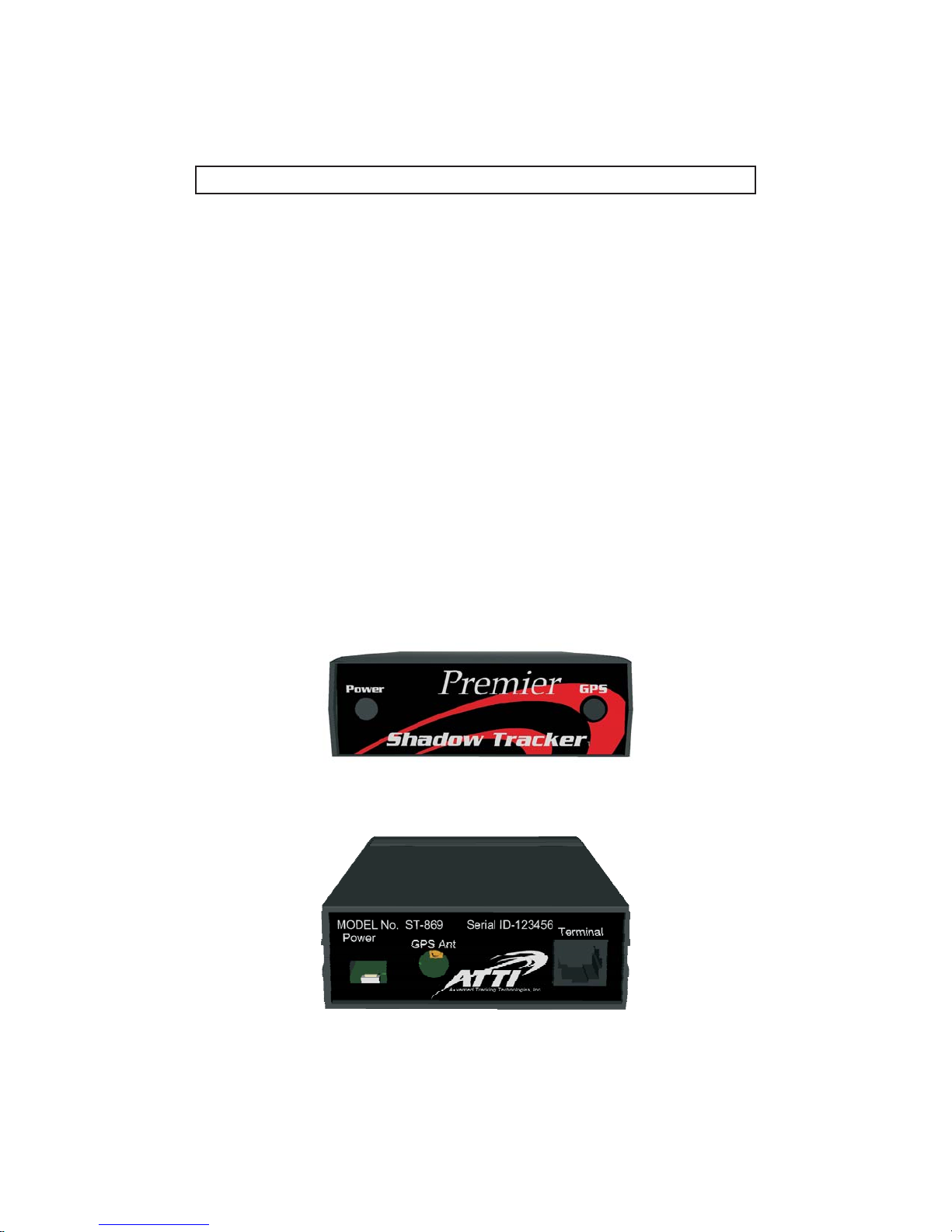
Carefully, connect the receiver adapter to the back of the Shadow Tracker unit
paying special attention not to bend any of the connector prongs.
The adapter should be connected to the vehicles power source.
Refer to: Wiring Instructions of this manual for further explanation.
™
3
Page 9
CONNECTING THE UNIT
Wiring Instructions
The Red wire must be connected to a CONSTANT 12 volt positive power source,
it MUST have power even when the vehicle is turned off. The Blue wire should
be connected to a switched 12 volt positive power source, it should have power
ONLY when the vehicle is running and NOT when the vehicle is turned off. This
tells the Shadow Tracker™ Premier unit that the vehicle is turned off verifying
that the vehicle must be stopped. If you can not locate a switched power source
then the Blue wire MUST be connected to the same constant power source as
the Red wire. (Note: If the Blue wire is connected to a continuous power source
then the stop reporting may not be as accurate. The Blue wire MUST be
connected to a power source, either constant or switched or the Tracker unit will
NOT collect GPS data.) The Black wire must be connected to a 12 volt ground
source.
Status Indicator Lights
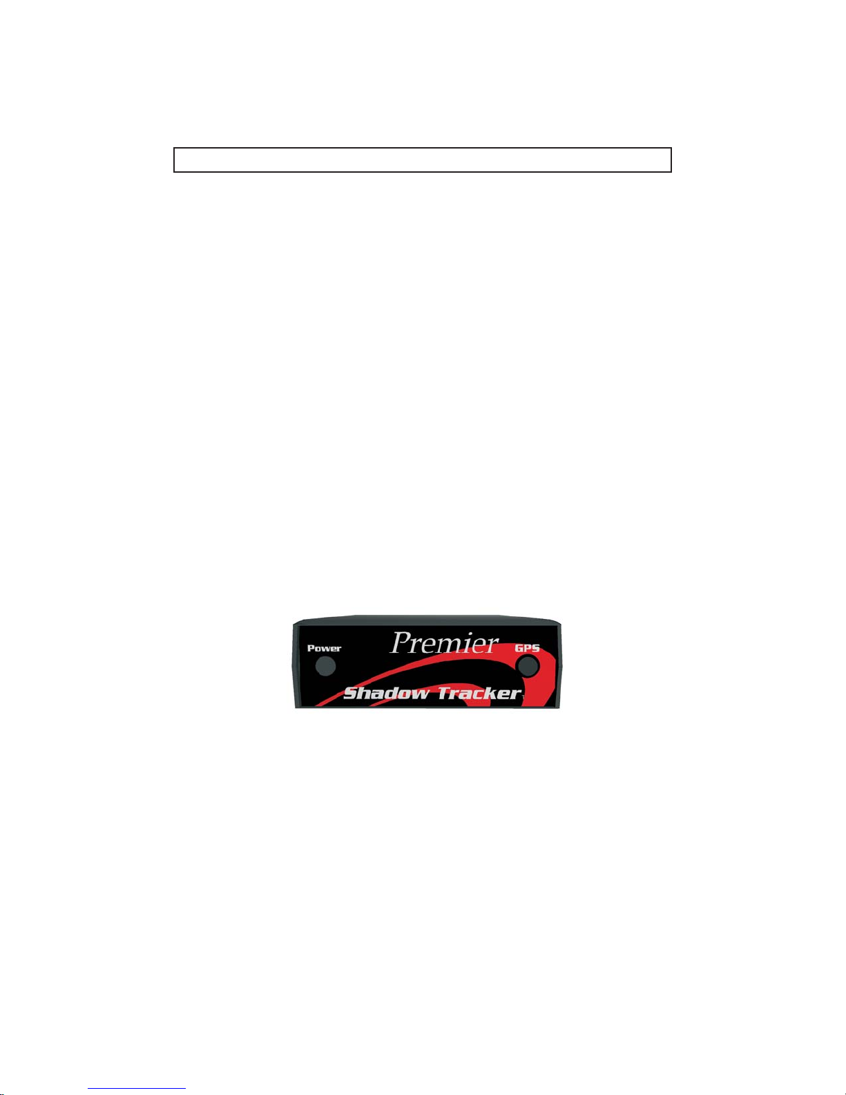
Once power is properly connected the LED and LED light located on
the front panel of the Shadow Tracker™ Premier will glow.
Power
The LED indicator will be red when the unit is receiving power. When the
unit is downloading the LED indicator will blink.
GPS
The LED indicator is green when satellite information is being acquired.
GPS
The light is orange when no satellites are visible and the unit is unable to
successfully track it’s position. If this occurs on a regular basis you may need to
reposition the antenna.
Upon the initial power up or after extended periods of non use it may take up to
10 minutes to acquire ( LED will turn green) satellites. Once the unit has
acquired, if power is turned off and on the acquisition time will normally be less
than one minute.
If the unit does not successfully power up, refer to the trouble shooting section located at the back of the manual. The unit
power should be disconnected when left for extended periods of time.
Transmit
GPS
Power GPS
Status Indicator Lights
4
Page 10

CONNECTING THE UNIT
The GPS Antenna
An GPS antenna is required, and must be connected to the Shadow
active
Tracker™ Premier for GPS data collection to occur. The antenna can be
positioned on the vehicle by either an internal suction mount or external magnetic
mount. Always place the antenna where the light remains green for
continuous tracking, otherwise mapping and reporting accuracy may decrease.
For best tracking results, it is recommended that you mount the antenna in a
place that has an unobstructed view of the sky.
GPS
Warning:
Crimping or cutting the GPS antenna cable may cause damage to the antenna
and the Shadow Tracker™ Premier unit.
Attaching a passive GPS antenna will result in damage to this device.
Downloading the GPS data to your PC
This unit does not require removal from the vehicle. The unit will automatically
notify the system server when in range and download it’s GPS information for
you.
5
Page 11

CONNECTING THE UNIT
Other Information
The Shadow Tracker™ Premier unit must remain connected to a continuous
power supply during vehicle movement for accurate location readings.
6
Page 12

SAFETY AND CARE
Safety
!
!
!
!
!
!
!
!
!
!
!
!
!
!
Do not place where spills can occur on the unit.
Do not place the unit near a heating device.
Do not place the unit in direct sunlight.
Do not subject the unit to electrical shock.
Do not pour liquid onto the unit.
Do not apply any physical pressure to the unit.
Do not place anything heavy on the unit.
Do not leave any objects on top.
Do not disassemble the unit or any of its components.
Do not scratch, twist, hit, or push the surface of the LED.
Do not use the unit when temperatures are below -40C or above 70C.
Always use the designated AC or DC adapter provided with the unit to
avoid the risk of fire or damage to this unit.
Do not disassemble the unit or any component of the product.
Use only power cables or antennas provided by Advanced Tracking
Technologies, Inc.
Caring for the Shadow Tracker™ Premier
Occasionally the Shadow Tracker™ Premier needs to be cleaned. Use the
following precautions.
Cleaning of the Shadow Tracker™ Premier unit
!
!
!
!
Use a soft cloth to wipe the exterior.
Do not use an alkaline detergent.
Do not use alcohol on the unit case.
Avoid excessive moisture when cleaning the unit.
Care of the antenna:
!
!
!
Do not crimp or cut the GPS antenna cable.
Do not place heavy objects on the antenna
Do not pull on the antenna connections or connectors
7
Page 13
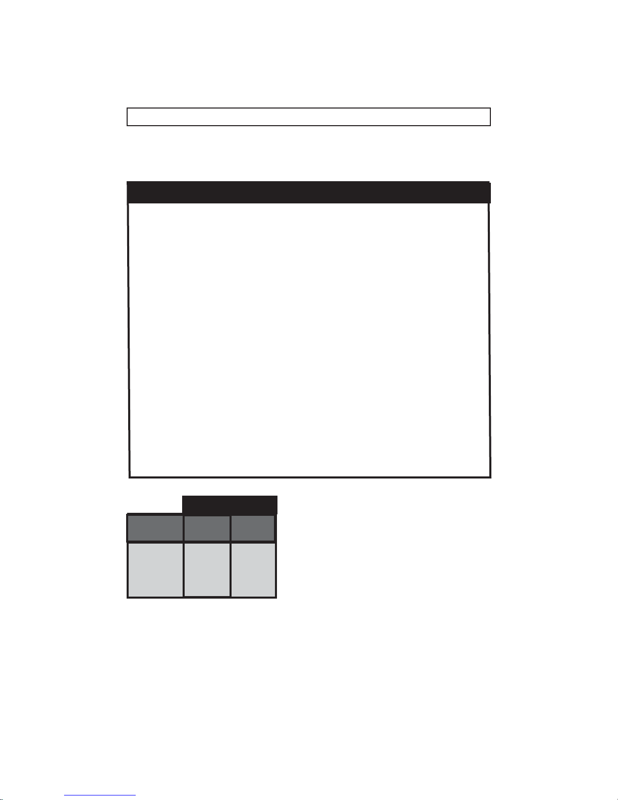
SPECIFICATIONS AND FEATURES
Shadow Tracker™ Premier at a glance
: 1.23 in.
Height
Width:
Length:
Weight:
Shadow Tracker™:Premier 10.00 oz
Magnetic mount antenna for transceiver
GPS Antenna
Current draw transmitting:
Current draw receiving:
Allowable voltage range:
Normal operating voltage:
Data download rate:
On board memory:
Operating temperature range:
Approximate data storage time:
Line of Sight:*
Frequency Range:
System Requirements:
Ram min.(64 MB recommended), 20 MB of free HD space, CD Rom, SVGA Monitor (17 in.
Recommended), Win compatible printer, 1 open 9 pin com port. Shadow Tracker ™ V3.0
software.
*With unity gain omnidirectional antenna. Ranges may be increased with varied antenna configurations, terrain and antenna
heights.
®
Windows NT,98 or 95, Pentium 233 Mhz processor min., 32 MB
®®
3.50 in.
6.18 in.
12.40 oz
2.6 oz.
850ma @ 12v
200ma @ 12v
9v to 18v DC
12v DC
115K Baud
512K
-20 to 70 C
1440 Hrs.
Up to 20 mls
902-928 Mhz
Time-To-First-Fix
Satellite
Acquisition
State
Warm
Initialized
Cold
Frozen
Typical
(minutes)
0.03
0.8
2.0
(*)
90%
Probable
(minutes)
0.4
1.0
2.5
(*)
Note that times are valid at 25 degrees Celsius with no
satellite signal blockage.(*)= Frozen start is considered
to be a recovery mode. An "out-of-the-box" board that
has not operated for a significant amount of time
(months) may approximate this state because the data in
EEPROM may be valid butexpired or partially complete.
8
Page 14
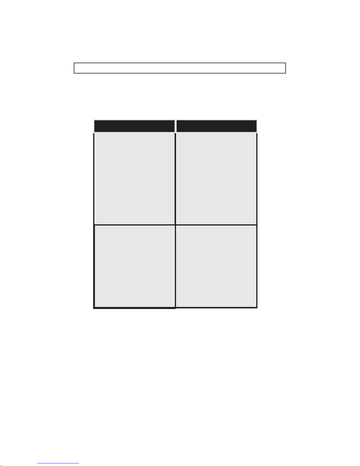
TROUBLESHOOTING
Problem
Unit LED does not
turn Red or Green.
Unit LED will not
turn green. Unit is
not receiving GPS
signal.
Action
!Make sure the
connection is made to
the back of the unit.
!
Check antenna
connection
!
Make sure the antenna
cable is not crimped or
cut .
!
Reposition the antenna.
9
Page 15

Revised 09/10/02 - JLanda
Page 16

P.O. Box 168
Sugar Land, Texas 77487
Tel: (800) 279-0035
Fax: (713) 353-6050
Www.AdvanTrack.com
 Loading...