


®
SMART
MTD
Active Monitoring
COMPLETE REFERENCE GUIDE
SMART® ACTIVE Monitoring
System Overview
Pro Tech’s Miniature Tracking Device (MTD) utilizes GPS satellites
to establish offender locations utilizing the components of the
SMART® MTD System.
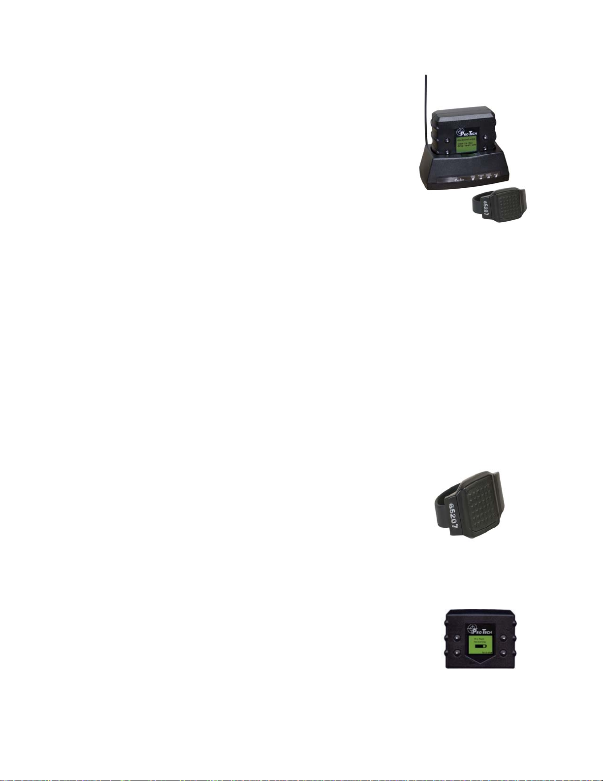
Pro Tech’s SMART System consists of four main components: The Ankle Bracelet, the
Miniature Tracking Device (MTD), the Base Unit, and Pro Tech’s Client Enrollment Software
(PCE).
SMART MTD-Active Mode Communication and GPS Point Storage
• The AMTD (Active MTD) calls Pro Tech every hour while out of the Base Unit, or
every 6 hours while in the Base Unit, while in compliance
• The AMTD will call Pro Tech as soon as a violation occurs
• If the AMTD is not able to make a call because of poor cellular coverage, it will
continue trying to call Pro Tech until it is successful
• The AMTD collects a GPS point every minute. If a Geographic Rule is in violation,
the AMTD will collect a GPS point every 15 seconds.
• The MTD has a battery saving feature that will place the MTD “At Rest” if it remains
motionless for 10 consecutive minutes
• When “At Rest” the MTD will collect a GPS point every
hour
• As soon as motion is detected, the MTD will come out of the
“At Rest” feature
Ankle Bracelet
• Serves as an electronic tether to the AMTD
Miniature Tracking Device-Active Mode
• A 15 oz. device, approximately twice the size of a
digital pager that clips to an offender’s belt. The
AMTD receives transmitted information from Pro
Tech’s ankle bracelet and the GPS satellites, and then
uses its modem to transmit the data using the cellular
network.
- 1 -
System Overview Cont.
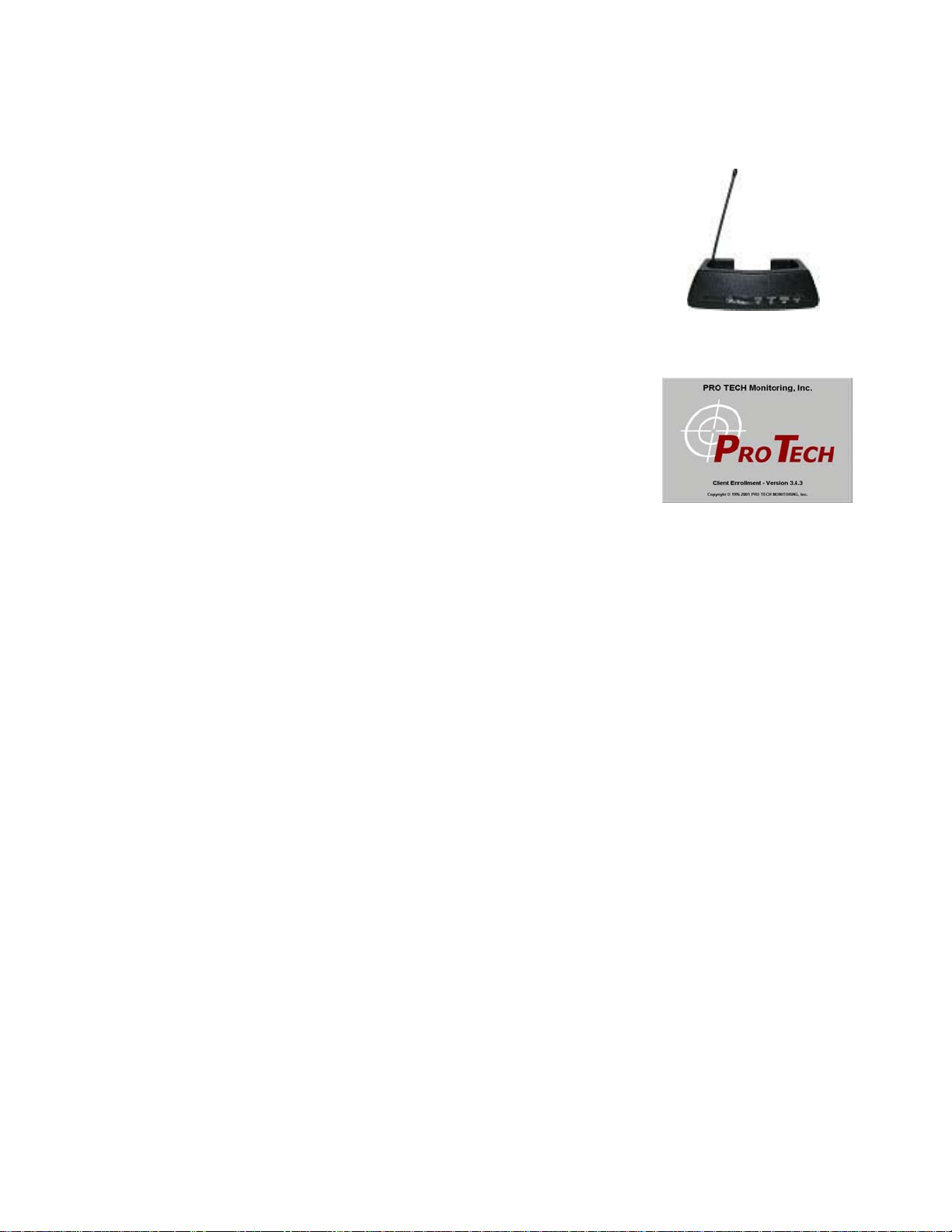
Base Unit
• A small stationary device used to recharge the AMTD
and transmits all information via a landline, if
available. It also monitors the Ankle Bracelet when
the AMTD is placed in the base unit (docked).
PCE
• The tracking and monitoring software that can be
installed on almost any computer with Internet
access. PCE provides access to maps, offender
information, and reports.
- 2 -

Rule Definitions
Hardware Rules
Bracelet Battery
• The bracelet battery is getting low; the bracelet must be replaced within 72 hours
Bracelet Gone
• Occurs when the offender is out of range of the tracking device. Therefore, the
location of the offender is unknown.
• Pro Tech adds a 5-minute buffer period to all Bracelet Gone violations – you may add
additional time. This is not a Grace Period. During this time the offender is not notified
of the Bracelet Gone. Only after 5-minutes have passed will the Bracelet Gone rule go
into violation. If you add a grace, it will apply after the 5-minute buffer has passed.
For example, if a 1-minute grace is set, the bracelet will have to be out of range for 6minutes before notifications are sent.
Bracelet Strap
• The bracelet strap has been compromised or removed from the bracelet
Base Unit A/C Power
• The Base Unit has lost A/C Power and is running on battery back up
Base Unit Phone Line Disconnect
• The phone line has been removed from the base unit. You will not get this alert until
the phone line has been reconnected, because the Base Unit requires a phone line to
report violations.
Base Unit Battery
• The Base Unit has been running on the back-up battery and is about to go dead. With
a full charge (24 hours) the back-up battery will last 16-20 hours. While running on
the back-up battery, the Base Unit will not charge the MTD. If the MTD is in the
Base Unit, and the Base Unit can call in, the MTD will still be able to successfully
download its information.
Base Unit Unable to connect
• The Base Unit has not called Pro Tech in 6 ½ hours
Base Unit Tamper
• The Base Unit has been compromised in some form
Phone Number Caller ID
• Signals the offender may have moved the Base Unit to a new phone line
• The number cannot be private or “unlisted”
- 3 -

Rule Definitions
Hardware Rules Cont.
MTD Battery
• The MTD Battery is low. The MTD needs to be placed in the Base Unit within 60
minutes. The offender receives the automatic message “Battery Low -Place in Base
Unit”.
MTD Tamper
• The MTD has been compromised in some form
Active MTD Unable to Connect
• It has been over 2 ½ hours since the MTD has called in. This is normally due to poor
cellular coverage in the area that the offender is located in. The offender is not
notified of the Unable to Connect and a message cannot be sent to the device. Once
the MTD is able to use the cellular network to call in, it will report the violation.
Motion No GPS
• Occurs when the MTD has accumulated 10 minutes of motion in a 60-minute period,
without receiving a signal from the GPS satellites
Home Curfew
• The MTD is NOT in the assigned Base Unit when the Home Curfew schedule is in
effect
Geographic Rules
Zone Rules- The offender has violated a Zone set up by the user
• Inclusion Zone
o Geographic areas like home, work, or school where the offender is confined
during an officer defined schedule
• Exclusion Zone
o Geographic areas used to define off-limits areas to the offender
- 4 -
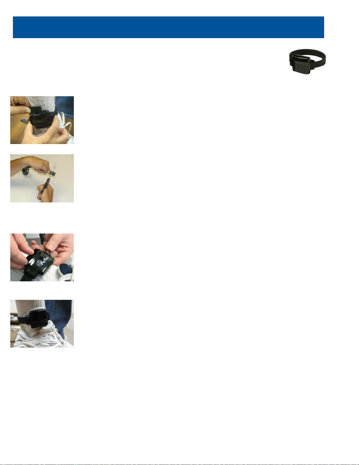
Activating the SMART MTD-Active Mode
Bracelet
Attaching the Bracelet
• Match the Bracelet serial number on the Bracelet case to the
number on the Bracelet serial number in the hardware list in
PCE. The ankle transmitter and strap will be shipped unattached.
You must insert one end of the strap into the transmitter and push
the locking pins into place. Make sure that the locking pins are
flush with the case. Measure the strap to the offender’s leg and
cut the strap to fit around the offender’s ankle. You should size
the strap so that it allows approximately ¼ inch of space between
the offender’s leg and the strap to ensure comfort.
• Once you have the strap attached, push the locking pin through
the holes on the bracelet and into the strap until it locks into
place
• Make sure the locking pin is pushed far enough so that the top of
the pin is flush with the bracelet case
- 5 -

Activating the SMART MTD-Active Mode
Bracelet
Removing the Bracelet
• Cut the strap
• Using the screwdriver provided, turn the right locking pin
counter clockwise and the left locking pin clockwise to
remove
• Lift each side of the pin up from the strap and remove.
Slide both ends of the strap out of its channel. Dispose of
the strap
• Clean the bracelet with mild detergent. Rinse, dry, and
return to your inventory
- 6 -

Activating the SMART MTD-Active Mode
Step 1:
Step 2:
Base Unit
figure 5.1
figure 5.2
figure 5.3
Step 3:
Connecting the Base Unit
Plug A/C adapter into a wall
outlet. (figure 5.1)
- 7 -
Plug A/C adapter into the
back of base unit where
POWER is located. (figure
5.2) The green power light will
light up on the front of the unit.
If offender has a phone line:
A: Remove phone line from
telephone and plug into the
back of the Base Unit marked
PHONE.
B: Take extra phone cord and
plug one end back into the
telephone and the other end
into Base Unit marked LINE.
(figu re 5.3)

Activating the SMART MTD-Active Mode
Step 4:
Base Unit Violation
Figure 5.4
figure 5.5
figure 5.6
Base Unit
Connecting the Base Unit Cont.
If activating at office:
A: Remove phone line from
facsimile machine. (figure 5.4)
B: Plug facsimile phone line
into base unit. (figure 5.5)
- 8 -
Status Lights:
Phone In Use
The Base Unit needs to
make a call, but the phone
line is in use.
No Phone Line
The phone line has been
disconnected.
Curfew Violation
AMTD is not in assigned
Base Unit when the
schedule is in effect.
A/C Power
Base Unit has lost power.

Activating the SMART MTD-Active Mode
Step 1:
Step 3:
figure 5.7
figure 5.9
Step 2:
Active Mode
figure 5.8
Place AMTD in the Base Unit.
Ensure that base unit is
connected to the A/C power cord.
(figu re 5.7)
Note: Always make sure the
AMTD is fully charged before
activation.
Note: Ensure that the hardware
has been assigned and saved
to the offender’s profile.
- 9 -
Press the Activate button.
(bottom right button)
(figu re 5.8)
Press Scroll button (top
right button) to select “Use
Wireless” to activate using
the cellular network. (figure
5.9)
If activating via the Base
Unit, select which pref ix (if
any) the Base Unit must dial
to complete a call. Refer to
Base Unit step 4 for
additional instructions.

Step 4:
Activating the SMART MTD-Active Mode
Step 5:
figure 5.10
Active Mode Cont.
Press Dial button. (bottom left button) (figure 5.10)
· The AMTD will begin to contact the Pro Tech data center and
“Contacting Data Center” will be displayed on the screen.
· Once contact is complete, the AMTD will begin to search for the
bracelet. “Searching for Bracelet” will be displayed on the screen.
Note: Both sides of the strap must be connected to the bracelet,
and it must be in range of the AMTD.
· Once the AMTD recognizes the bracelet, it will display “Waiting
for GPS”. Remove the AMTD from the Base Unit.
Note: Do not remove the AMTD from the Base Unit until this
message appears. Be careful not to touch any buttons or the
activation will be canceled and you will have to start over.
figure 5.11
Walk the AMTD outside,
holding it upright in an area
with a clear view of the sky.
(figure 5.11)
The status bar will gradually
move towards the right,
indicating that the GPS signal
is in the process of being
acquired. Once GPS has
been acquired, the AMTD will
beep and display the
message “GPS A cquire d
- 10 -

Activating the SMART MTD-Active Mode
Step 6:
figure 5.12
Active Mode Cont.
Press the Acknowledge button. (top left button) (figure 5.12)
Note: You may also push the Acknowledge button while
outside.
Activation Complete
The offender’s name, date, time and battery status indicator will be
displayed on the AMTD’s screen.
Note: It is recommended that after activation, click the
Download All Points icon, followed by the Display Last Position
icon to verify that GPS has been acquired.
- 11 -

DEACTIVATING SYSTEM HARDWARE
• In PCE, go to the Hardware Tab and click
the Deactivate Hardware button. The
following screen will appear. Check the
items that you wish to deactivate and the
reason for the deactivation. Click the
Commit button at the bottom of the screen.
• The AMTD needs to call in to download any
stored information and receive the
Deactivation Command
• When an AMTD has been successfully
deactivated, the LCD screen will display
“Remove from Base Unit”
- 12 -

Enrolling an Offe nde r Quic k Re fe r e nc e
Open PCE.
Enter Contact Information
Enter Demographic Information
Select Time Zone
Go to the Reports Tab
Select which DVSR(s) you wish to receive
SAVE
Select View and Refresh Contacts to Update the PCE server
NOTE: You only need to enter a contact one (1) time
Offender Information
Enter Demographic Information
Select Time Zone
Select Level of Supervision (Equipment)
Enter Personal information (optional)
Enter Employment information (optional)
Enter Educational information (optional)
Enter Sentencing information, enter Offense (optional)
Enter Photo (if desired)
Enter Rules
Highlight specific Rule
Do you want the offender to receive notice of the violation?
Set a Grace Period (if desired)
Enter Actions for Hardware Rules
Choose a Contact; Page, Fax, Email
Enter Inclusion Rules for specific offender
Choose a radius
Choose a Grace Period (if desired)
Do you want the offender to receive notice of violation?
Map the Address
Choose a schedule
Choose a Contact on the Actions Tab; Page, Fax, Email
- 13 -

Enrolling an Offender Quick Reference Cont.
Enter Exclusion Rules for specific offender
Choose a radius
Choose a Grace Period (if desired
Do you want the offender to receive notice of violation?
Map the Address
Choose a schedule
Choose a Contact on the Actions Tab; Page, Fax, Email
SAVE
Hardware Installation, Assignment and Activation
Size the bracelet and strap to fit snuggly on the offender’s ankle
Cut the strap to fit and secure locking pins.
Assign MTD, Base Unit, and Bracelet to offender in PCE Hardware tab
SAVE
Place MTD in Base Unit and follow Activation Procedure on page 8
Take unit outside to acquire GPS. Wait for Activation Successful message
Have the MTD call in. Allow a few minutes for the unit to connect to the data center
Display Last Position in PCE
The map and one GPS tracking point will appear
Deactivation
Choose offender in PCE
Go to Hardware tab
Choose Deactivate Hardware and Commit
Select a reason for the deactivation of the MTD
- 14 -

FCC Statement
This equipment has been tested and found to comply with the limits for a Class B digital
device, pursuant to Part 15 of the FCC Rules. These limits are designed to provide
reasonable protecti on ag ai nst harm ful i nterference in a residential installation.
This equipment generates, uses, and can radiate radio frequency energy and, if not
installed and used in accordance with the instructions, may cause harmful interference
to radio communications. However, there is no guarantee that interference will not occur
in a particular installation. If this equipment does cause harmful interference to radio or
television reception, which can be determined by turning the equipment off and on, the
user is encouraged to try to correct the interference by one of the following measures:
• Reorient or relocate the receiving antenna.
• Increase the separation between the equipment and receiver.
• Connect the equipment into an outlet on a circuit different from that to which
the receiver is connected.
• Consult the dealer or an experienced radio/TV technician for help.
To assure continued compliance, any changes or modifications not expressly
approved by the party responsible for compliance could void the user's authority to
operate this equipment. (Example - use only shielded interface cables when
connecting to computer or peripheral devices).
This device complies with Part 15 of the FCC Rules. Operation is subject to the
following two conditions:
(1) This device may not cause harmful interference, and
(2) This device must accept any interference received, including interference that
may cause undesired operation.
- 15 -

SAR Statement
This equipment complies with FCC RF radiation exposure limits set forth for an
uncontrolled environment.
The max SAR value as measured in the SAR report is 0.983W/Kg.
The belt clip is designed to maintain a safe distance between the equipment and the
user’s body. Do not attach the equipment to the body using any non-approved
accessories. Using unapproved accessories may violate FCC RF exposure limits.
- 16 -
 Loading...