

Page 1
SHENZHEN ATTEN TECHNOLOGY CO., LTD.
Soldering Iron Soldering Staon
Mul funcon Rework System
Regulated DC Power Supply
Programmable Power Supply
RF Microwave Instruments RF Microwave Components
Aenuator Amplifier Coaxial Load
Hot Air Rework Staon
BGA Rework System
Switching DC Power Supply
SOLDERING STATION
USER’S MANUAL
SHENZHEN ATTEN TECHNOLOGY CO., LTD.
THE
INSTRUMENTS BRAND IN CHINA
©2014 ATTEN CORPORATION
MADE IN CHINA
CBN027457 (A)
S/N
SHENZHEN ATTEN TECHNOLOGY CO., LTD.
©2014 ATTEN Corporaon
Page 2

Content
Content
Copyright...............................................................................................................................2
SymbolsandConventions..................................................................................................2
AssumptionForUser...........................................................................................................2
Safety.....................................................................................................................................2
Disclaimer..............................................................................................................................2
ItemCheckList.....................................................................................................................3
ProductOverview................................................................................................................3
Features.................................................................................................................................3
Specifications........................................................................................................................3
FirstGlance...........................................................................................................................4
LCDDisplayPanel.................................................................................................................4
OperationalGuide...............................................................................................................5
Maintenance......................................................................................................................... 9
Troubleshooting...................................................................................................................9
ServiceContact...................................................................................................................10
Appendix.............................................................................................................................10
..................................................................................................................................1
Warranty
Thisproductwarrantyperiodcover12monthsfromthedaythis
productpurchased.Wewillmakefreemaintenanceforanyquality
problemitselfifthiscardandreceiptprovided.We willrepairand
return your device within 2 workdays after receiving repairing Ͳreq
device.
Note:pleaseattachthiswarrantycardif
devicetoberepairedwithoutcharge.
youwantyour
CertificateofProduct
ModelὉ______________ProductNO.Ὁ___________
QCὉ_________________ProductiondateὉ________
SalesclerkὉ___________SaledateὉ_____________
1
Page 3
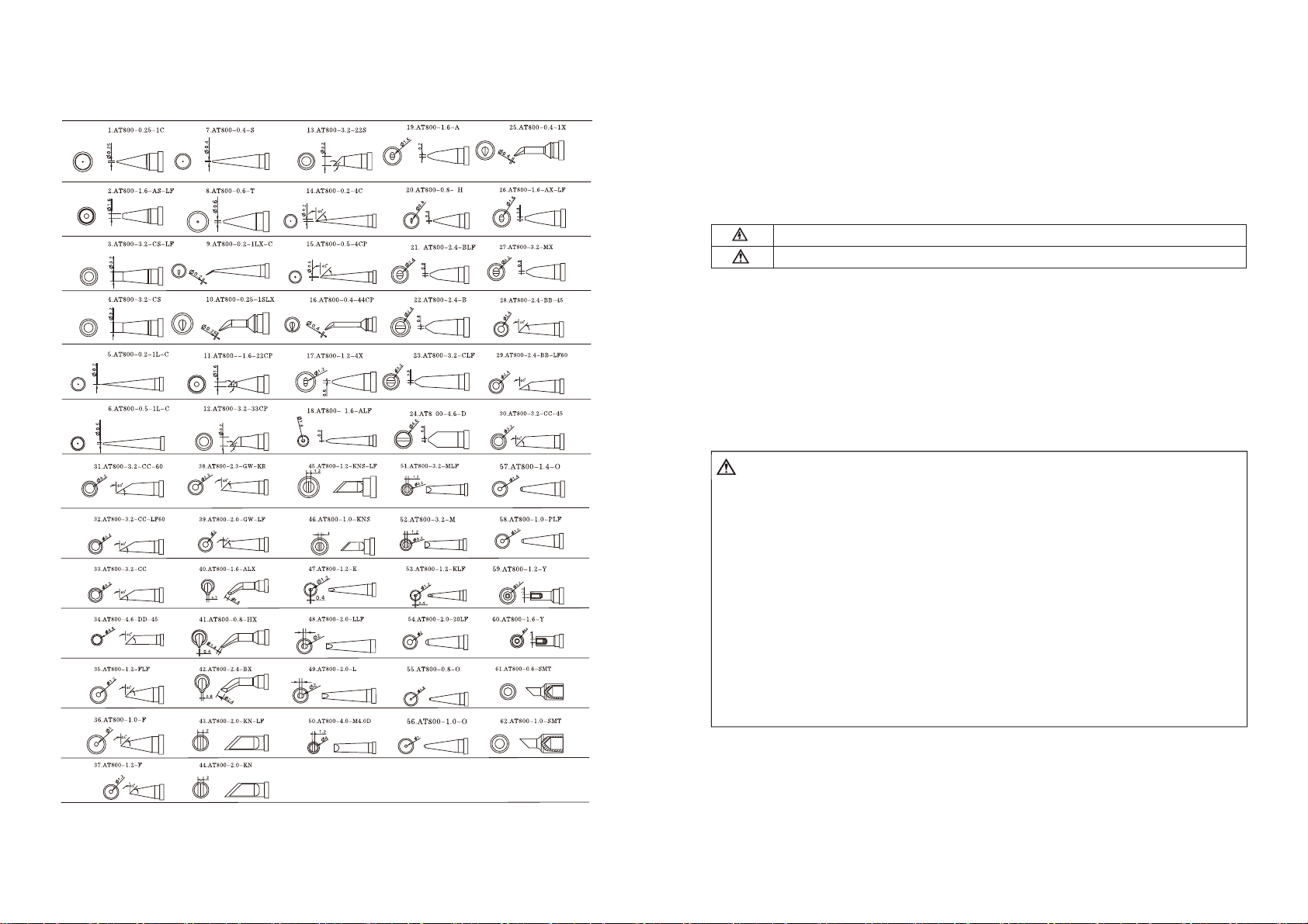
Interchangeable soldering Ɵp ƐƉĞĐŝĮcaƟŽŶƐ (AT800 series)
Copyright
Thedesignofthisproduct(includingsoftware)anditsaccessoriesisundertutelageoflaws.Any
actiontoviolaterelevantrightofourproductwillbepenalizedthroughlaw.Pleaseconsciously
observerelevantlocallawsintheuseofthisproduct.
Symbolsandconventions
Thankyouforpurchasingthissolderingstationproduct.Pleasereadthismanualcarefullyandpay
attentiontowarningsandprecautionsmentionedhereinbeforeusingthisproduct.
Warningyouagainsttheriskofelectricshock.
Warningyouagainsttheriskofphysicalinjury.
Assumptionforuser
Weassumethatuserhavecommonsenseandbasicrelevantelectricaloperationknowledgebefore
usingthisproduct.Thisdeviceisnotintendedforusebypersons(includingchildren)withlimited
physical,sensoryormentalaptitude,orbypersonswholackknowledgeorexperienceinhandling
thedevice.Thisappliancecanbe
usedbychildrenagedfrom8yearsandaboveandpersonswith
reducedphysical,sensoryormentalcapabilitiesorlackofexperienceandknowledgeifthey
havebeengivensupervisionorinstructionconcerninguseoftheapplianceinasafewayand
understandthehazardsinvolved.Childrenshallnotplay
withtheappliance.Cleaninganduser
maintenanceshallnotbemadebychildrenwithoutsupervision.
Safety
WAR NIN G: Thesolderingtiptemperaturecanreach150Ć~480Ć asthisproductinworking
status.Usershouldobeyfollowingrulesrigorouslyinviewofimproperoperationwillcausefiresor
burns.
dž Nevertouchsolderingtipandsurroundingmetalpartofsolderingtipbeforesolderingtip
cooldowncompletely.
dž Neverusethisproductaroundflammableobjects.
dž Alwaysturnswitchoffafteroperationandalwaysturnswitchofffortemporary
notͲoperation.
dž Usermustwaitingsolderingironcooldowncompletelyafterturningswitchoffforthe
replacementofsolderingtipandinternalparts.
dž Neveroperateonproductforthosewhohavenoexperienceorhavenobasicknowledgefor
thecircumstanceofnoguidance.
dž Keepthisproductoutofreachofchildren.
dž Neverplaceproductandpartofitinwateroroperateasyourhandsarewet.
dž Pleasekeepworkplacewellventilatedforfumesproducedinsolderingwork.
dž Neverplaywithotherswhileusing this product.
Disclaimer
dž
Forphysicalinjuriesandpossessionslosscausedbythosereasonswhicharenotrelatedto
productqualitysuchasoperatingwithoutfollowingmanualguide,naturaldisastersorforce
majeure,wetakenoresponsibilityforthat.
dž
UnderthesupervisionofShenzhenAttenTec h nolo g y Co.,Ltd,thismanualhasbeencompiled
andpublishedwhichcoveredthelatestproductdescriptionandspecification.Thecontentof
13
2
Page 4
dž thismanualissubjecttochangewithoutnotice.
ATTENTION:To avoiddamagingtounitandkeepoperationsafe,pleasereadtheinstructionmanual
aheadandkeepitaccessibleforanyoperator.
Itemchecklist
Name Quantity
Solderingstation 1Unit
Solderingiron 1PCS
Ironsupportingstand 1Unit
Powercord 1PCS
Manual 1Copy
Sponge 1Unit
Productoverview
STͲ60/STͲ80/STͲ100isanewdesigneddigitalsolderingstationwhichgotbetterperformanceandis
moreconvenientandsafertouse.Andithasbeenwidelyusedincolleges&universities,institutes,
industrialproductionlineandsoon.
Features
dž BrandnewdesignandLCDdisplaywhichcandisplayvarioussettingvalues.
dž Newdesignedmenuenablesystemsettingeasier.
dž VisualcontroloveroperationprocesswhichAnalogueheatingͲupstatusbartoindicateheating
upstatusandvisualsetting.
dž 3keystostoreandretrievefrequentlyusedtemperaturevaluesquickly.
dž Providetemperaturelockingfunctiontomakeproductionlinemanagementconvenient.
dž Smartstandby,shutdownfunction,adjustablestandbytimeandadjustableshutdowntime
enablemoreenergysavedandenvironmentfriendly.
dž Tou c hto n e couldbeturnedoffandon.
dž Tem p e ra t u re calibrationwasdesignedtobemorepreciseandmoreconvenienttokeepthis
productingoodperformanceforalongtime.
dž ThisproductwasdesignedwithlowͲvoltageheatingheaterwhichiscompletelyseparatedfrom
powersupplytokeepsolderingworksafer.
dž Thisproductwasdesignedtobecompatiblewithgeneral900Mseries(onlyforSTͲ60/STͲ80)
solderingtipwhichwasassembledseparatelywithheatingheatertocutusercostsdown.
dž Separatedironstandtosaveroomandtomakesolderingstationlayouteasier.
Specifications
InputVoltage AC(100V/110V/120V||220V/230V/240V)50/60Hz(optional)
Power 60W 80W 100W
Heatingelementvoltage 26VAC 28VAC 28VAC
Temp e ratu r eRange
Temp e ratu r ecalibrationrange
Temp e ratu r eprecision
STͲ60 STͲ80 STͲ100
150Ͳ450Ć/302Ͳ842
Đ
d50Ć/d90
d15
Ć d10Ć d10Ć
150Ͳ480Ć/302Ͳ896Đ150Ͳ480Ć/302Ͳ896
Đ d50Ć/d90Đ d50Ć/±90Đ
Đ
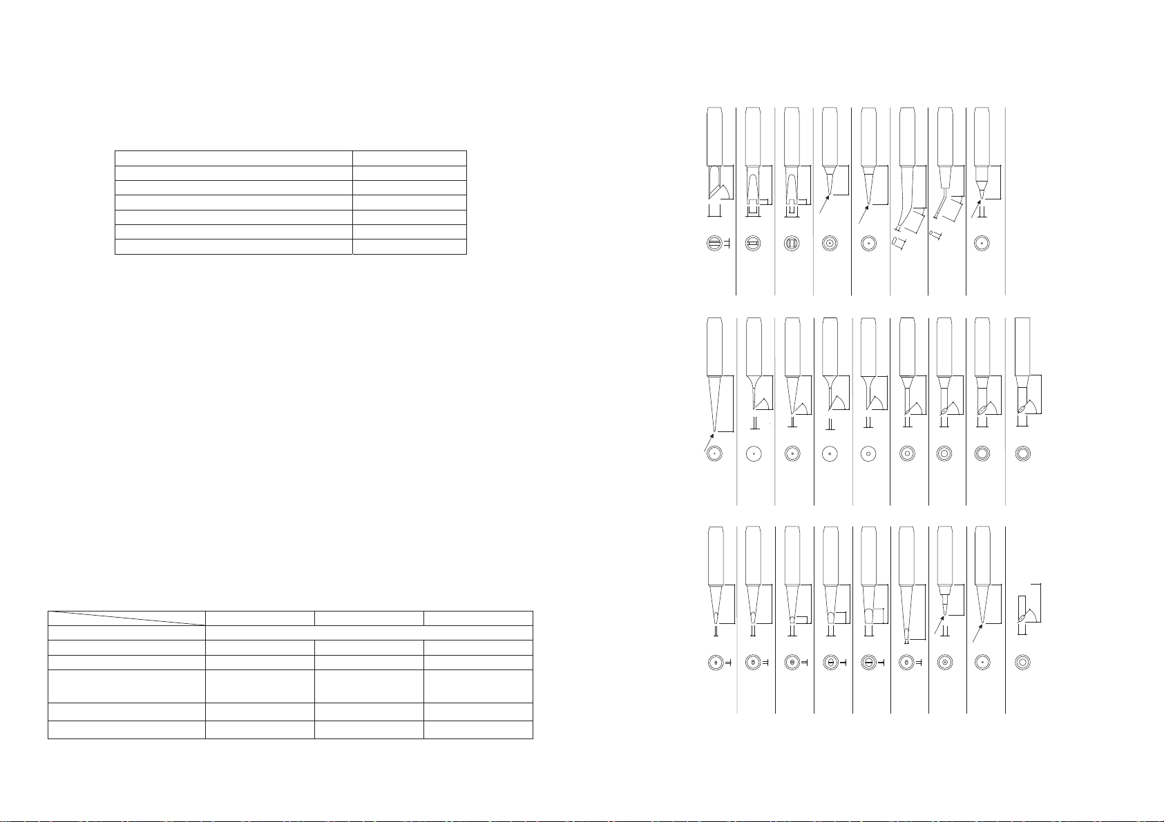
Interchangeable soldering Ɵp ƐƉĞĐŝĮcaƟŽŶƐ (900M series)
15(0.6)
2(0.08)
17(0.66)
(0.08)
(0.08)
2
2
2
3.2
(0.1)
Φ5.1
Φ4.2
(0.2)
(0.17)
45°
Φ5
(0.2)
17(0.66)
(0.08)
R0.2(0.008)
13(0.51)
R0.2(0.008)
900M-T-K
900M-T-R
900M-T-RT
900M-T-SI
900M-T-I
R0.2(0.008)
25(0.98)
15(0.6)
45°
0.5(0.02)
45°
Φ0.8
(0.031)
17(0.66)
60°
1(0.04)
15(0.6)
900M-T-LB
900M-T-0.5C
900M-T-0.8C
900M-T-1C
900M-T-1CF*
900M-T-1.5CF*
Φ0.8
(0.031)
17(0.66)
0.6(0.024)
Φ1.2
(0.047)
17(0.66)
0.7(0.028)
Φ1.6
(0.06)
(0.1)
3
17(0.66)
0.5(0.02)
Φ2.4
(0.09)
(0.2)
17(0.66)
5
0.5(0.02)
900M-T-0.8D
900M-T-1.2D
900M-T-1.6D
900M-T-2.4D
900M-T-3.2D
Φ1.5
(0.06)
Φ3.2
(0.12)
60°
(0.25)
17(0.66)
15(0.6)
17(0.66)
6.5
1.2(0.04)
(0.29)
3.5(0.13)
900M-T-H
Φ2
(0.08)
900M-T-2C
Φ1.2
(0.047)
0.5(0.02)
900M-T-1.2LD
19(0.74)
25°
1(0.04)
7.5
900M-T-1.8H
17(0.66)
45°
900M-T-2CF*
900M-T-3C
25(0.98)
R0.2(0.008)
0.7(0.028)
900M-T-SB
(0.29)
1.8(0.07)
Φ3
(0.1)
Φ2
(0.08)
14(0.5)
25°
R0.25(0.01)
7.5
900M-T-S4
17(0.66)
45°
900M-T-3CF*
900M-T-4C
14(0.55)
R0.5(0.02)
900M-T-B
15(0.6)
Φ2
(0.08)
17(0.66)
45°
Φ4
(0.16)
900M-T-4CF*
17(0.66)
(0.66)
17
55°
Φ4
(0.16)
900M-T-S11*
(0.66)
17
55°
Φ3
(0.1)
900M-T-S10*
3
12
Page 5
PartsList
Number Materialname Number Materialname
Powercord
Fuse(T1.0A|220V/230V240V),(T2.0
A|100V/110V/120V)
Malesocket
Solderingironstand
Cleaningsponge
Housing
PCBAfixingscrews
PCBAboard
Transformersfixingscrews
Transformers
Bottomhousing
Fixingscrewsforbottomhousing
Machinebase
Frontpanel
Transparentmask
Keygroup1
Keygroup2
Powerswitch
Outputreceptacle
Solderingironhandlecables
Solderingironhandleendsleeve
Solderingironhandleend
Solderingironhandlesleeve
Solderingironhandle
Heatingelementunit
Fixingbase
Solderingtip
Fixingswivelnut
Solderingtipfixingtube
Temp e ratu r eStability
STͲ60 STͲ80 STͲ100
d2
Ć
ἷinstillair,withoutloadἸ
AutomaticallystandͲbytime 1Ͳ120minutes
Ć
Standbytemperature
150
Automaticallyshutdowntime 1Ͳ120minutes
Temp e ratu r eregulation 5digits(default)/1digit(finetuning)
Heatingelement
Highperformance
dualͲwireheater
HighendquadͲwire
heater
Silveralloyheater
Temp e ratu r elock Yes
Beeping Yes
TipͲtoͲgroundimpedance <2ɏ
TipͲtoͲgroundvoltage <2mV
Volume 175(L)*115(W)*95(H)mm
NetWeight 1.85KG 2.36KG 2.4KG
Solderingtips
900M
series(Appendix)
900M
series(Appendix)
AT8 0 0
series(Appendix)
ĄTheabovespecificationsaresubjecttofurtherchangewithoutnoticeandrefertoactual
products.
ĄItisnotrecommendtosetworkingtemperatureabove450Ć foralongtimetokeepthis
productlifespanlonger.
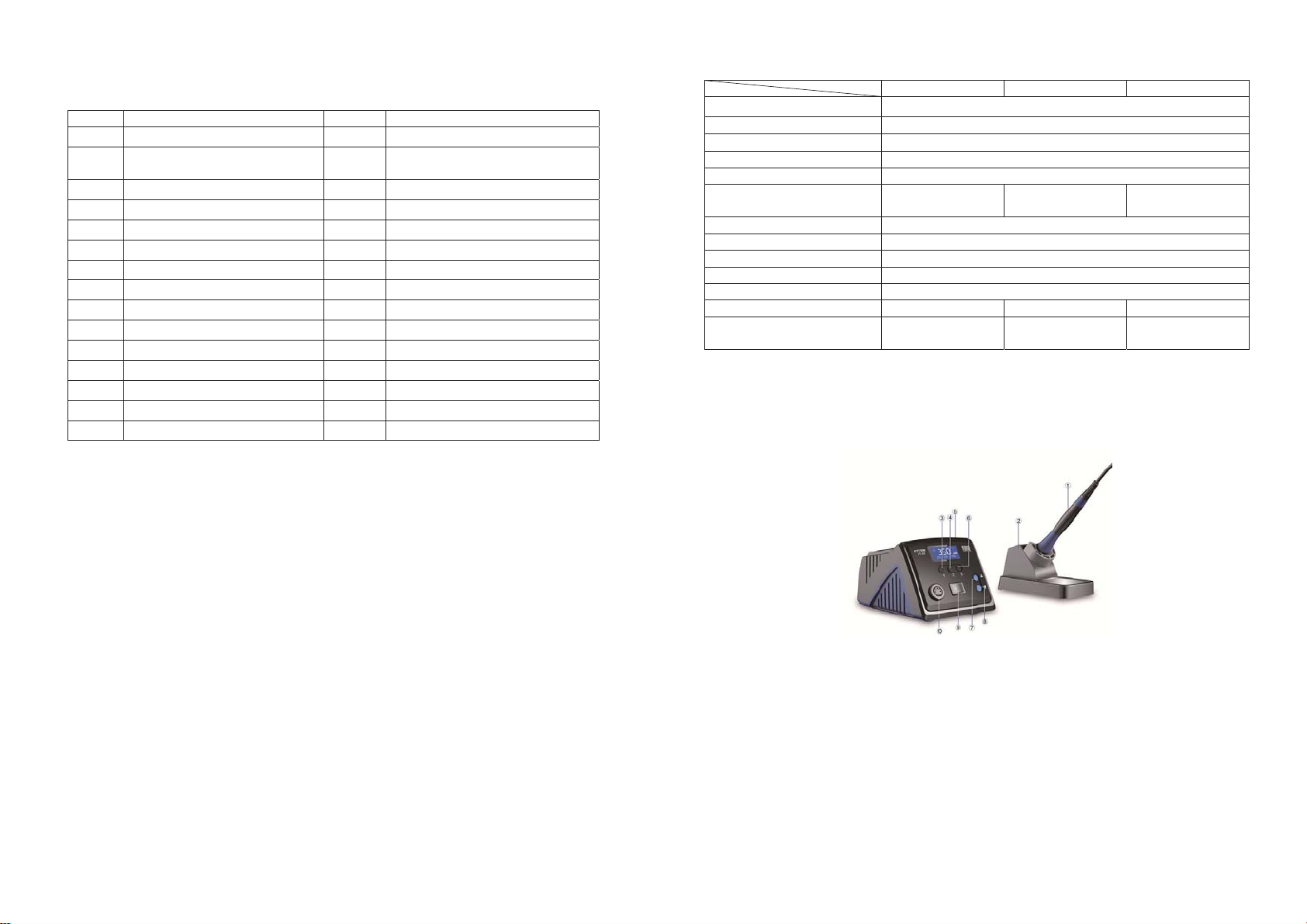
Firstglance
ŀ Ironhandpiece
Ł Ironstand
ł Presetkey1
Ń Presetkey2
ń LCDscreen
ŀ Presetkey3
Ł Upkey
ł Downkey
Ń Powerswitch
ń Handpiecereceptacle
11
LCDdisplaypanel
4
Page 6
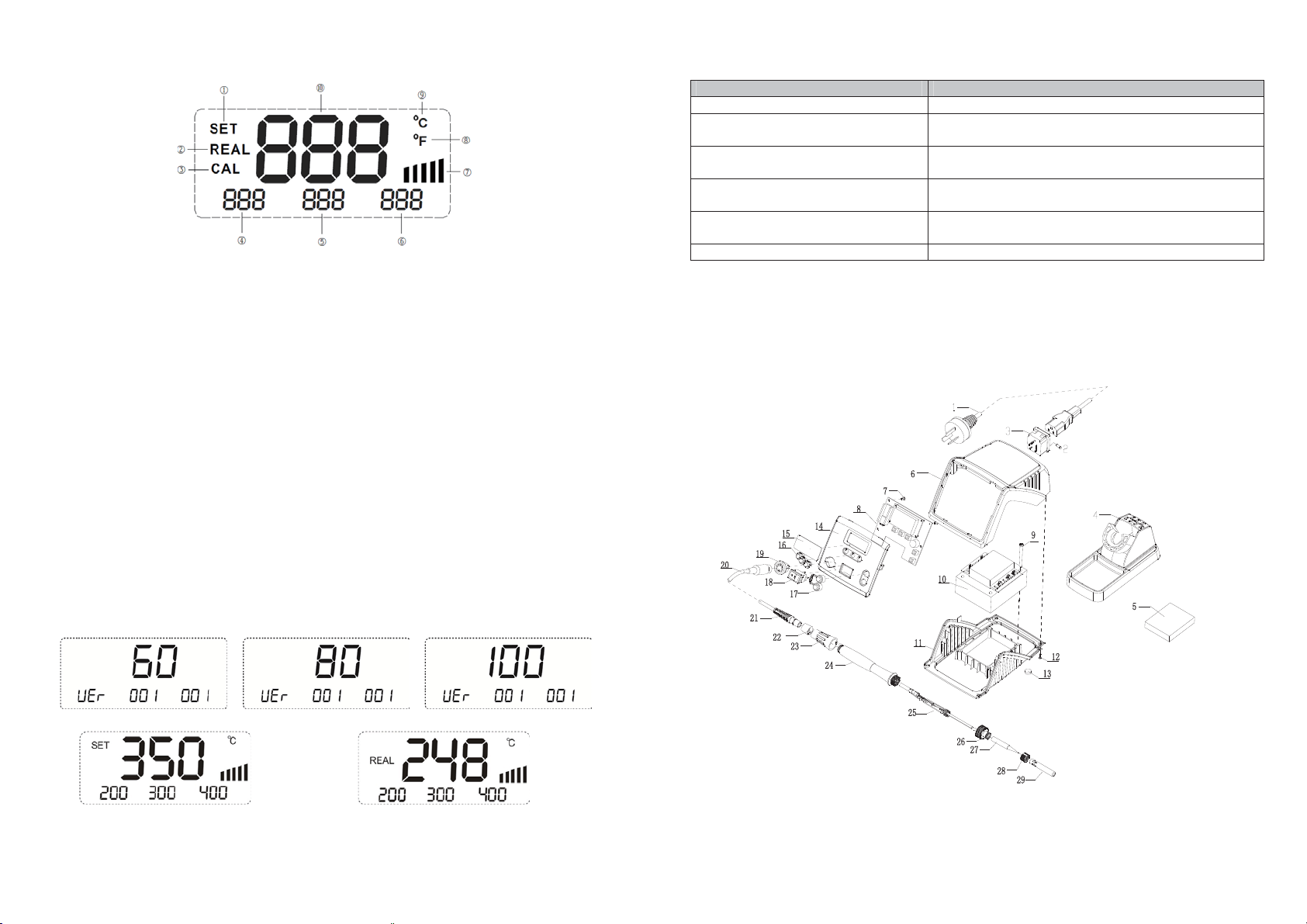
LCDdisplayDescription:
ŀ SET(SetMode):indicatesolderingstationentersettingmode;
Ł REAL(RealMode):indicatesolderingstationenterrealͲtimedisplaymode;
ł CAL(Calibration):indicatesolderingstationentertemperaturecalibrationmode;
Ń ShowthetemperaturevaluestoredinexpressstoreͲandͲretrievalchannel1
ń Showthetemperaturevaluestored
inexpressstoreͲandͲretrievalchannel2
Ņ ShowthetemperaturevaluestoredinexpressstoreͲandͲretrievalchannel3
ņ AnalogueheatingͲupstatusbartoshowcurrentheatingstrength.
Ň IndicatecurrenttemperaturescaleisFahrenheit.
ň IndicatecurrenttemperaturescaleisCelsius.
ʼn DisplaysolderingtiprealͲ
timetemperaturevalues.
Operationalguide
1.Connection
ŀ Plugsolderingironpowerendintoreceptacleonsolderingstationfrontpanelandplace
solderingironhandleinsolderingironsupportingstand.
Ł Plugpowercordfemaleplugintoreceptacleonsolderingstationrearpanel.(Pleaseassure
powersuppliedisfitforthisproduct).
2.PowerͲon
switchonafterpowercordconnection.LCDdisplaypanelwilldisplaysystemversionnumber
Tur n
for1seconds,thenLCDdisplaypanelwillshowlastsettemperaturevalueandshow"SET"
simultaneously(Figure1).3secondslater,displaypanelwillshowsolderingironrealͲtime
temperaturevalueand"REAL"atthesametime(Figure
STͲ60VersionDisplaySTͲ80VersionDisplaySTͲ100Versi onDisplay
2).
FaultCodeOrMalfunctionDescription CausesForMalfunction
dž Shortcircuitforheaterorsolderingironwires
EͲ1:AbnormalheatingͲupalarming dž Opencircuitforheatingelement.
dž Connectionerrorforheatingelement.
EͲ2:Opencircuitalarmingforsensors dž Heaterdamaged.
dž Wiringerrorofheatingelement.
Notwellconnected dž Checkpowercordplugandfuse(Pleasereplaceitwith
samespecification).
Temp e ratu r edisplayedisnotcorrect dž Pleasecheckwhetherthesolderingironisdamagedand
calibrateitagain.
Unreadablecode dž Switchpoweroffandrestartsolderingstation.
ĄAftermalfunctionoccurred,maintenanceworkshouldbedonethroughassignedtechnicianby
originalmanufacturerorqualifiedtechnician.
Servicecontact
ServiceDepartmentTel :(+86)0755Ͳ61618282
Appendix
Machineexplodedview:
Figure1 Figure2
3.Settingtemperature
Innormalworkingstate,pressŸorźtoadjusttemperatureandentertemperaturesettingmode
5
10
Page 7
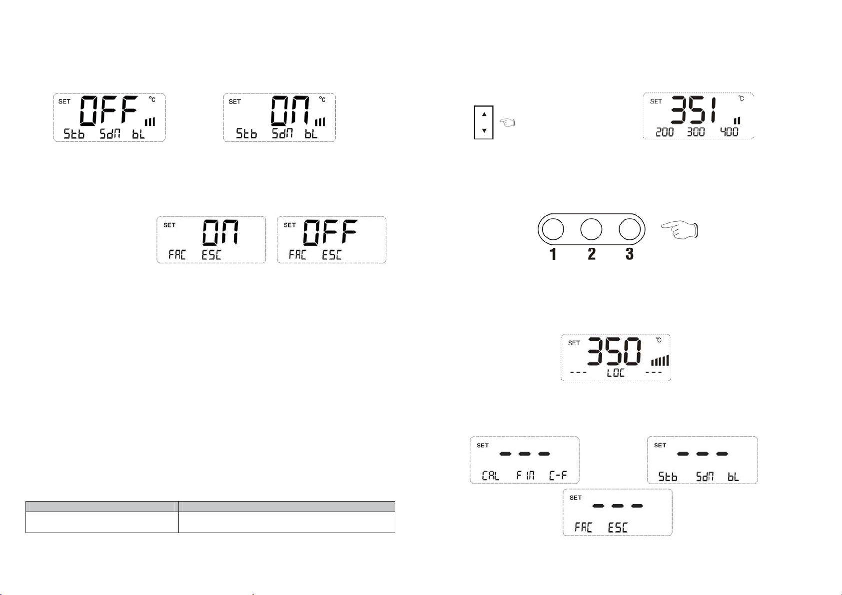
touchtonesettingmodeanddisplaypanelwillshowcurrenttouchtonesettingstatus.PressźorŸ
tosettouchtonestateandpress#3tosaveit.
Note:Beepingfunctionisenableassettingcontentis"ON”,andnowtherewillariseshortbeepfor
eachoperationoncontrolpaneltocall
yourattention.
(Figure4),"SET"willshowonLCDdisplaypanelsimultaneously.PressingandholdingŸorźcan
adjusttemperaturequickly.Stoppressingwillcausesolderingstationstoresettingvalue
automaticallyandexitfromtemperaturesettingmode.
Figure21 Figure22
13.Restorefactorysettings
12.1Insystemsettingmode,pressźtogotothirdsettingpage(Figure8).Thenpress#1toenter
factorysettingsrestorationmode.PressźorŸtochooseresettingpageornot.Afterresetting,
solderingstationsystemsettingswillberesetasfollows:
CAL(Usertemperature
calibrationvalue):Cleared.
FIN(fineͲtuning):OFF
CͲF(Temperaturescales):Celsius
STB(AutomaticStandby):OFF
SDN(Automaticshutdown):OFF
BL(Beeping):ON
Ć
Expresstemperature1:200
Expresstemperature2:300
Expresstemperature3:400
Ć
Ć
ڏ
ڏ
14.Exitingsystemsettingquickly
14.1Insystemsettingmode,pressźtogotothirdsettingpage(Figure8)asuserwanttoexit
systemsettingmodequickly(DefaultautomaticͲexitingtimeis10seconds),thenpress#2toexit
systemsettingmode.
Maintenance
dž
Toensurethisproductlifespanwillnotbeshortened,usermustpayattentiontofollowing
mattersinusingthisproduct.
dž
Donotusethisequipmentforotherpurposesexceptsolderingwork.
dž
Donotracksolderingironshandletoremoveresiduesolderonsolderingtipwhichwilldamage
thisunit.
dž
Donottamperwiththisproductanditsinternalcomponents.
dž
Donotmodifythisproductanditsinternalparts.
dž
Pleasechooseaccessoriesproducedbyoriginalmanufacturerforreplacingparts.
dž
Pleasegraspplugratherthancablesforpullingplugout.
Troubleshooting
FaultCodeOrMalfunctionDescription CausesForMalfunction
EͲ0:Abnormalheatingalarmofheater.
dž
Transform er damaged
dž
PowerMOSFETdamaged
Figure3 Figure4
4.Storingandretrievingtemperaturevaluesquickly
dž
Retrievetemperaturevalues:innormalworkingstate,press1,2,3(Figure5)toretrieve
temperaturevaluesstoredinmemoryandsetretrievedvalueascurrentworkingtemperature.
dž
Storetemperature:innormalworkingstate,pressandhold(over3seconds)1,2,3tostore
currentsettemperaturevaluesintomemory.
Figure5
5.Lockingoperationkeys
dž
Innormalworkingstate,pressingandholding1,2,3simultaneouslyover3secondscanlock
currentsettemperaturevalue.Nowanyoperationoncontrolpanelwillmakenosensewhich
indicateoperationkeysislocked.
dž
InkeyͲlockingmode,pressingandholding1,2,3simultaneouslyover3secondscanremove
lockingstateasyouwantto.
Figure6
6.Systemsetting
6.1Asuserneedtosetsystemparameters,usershouldentersystemsettingmodefirst.Pressand
holdŸandźsimultaneouslyover3secondstoentersystemsettingmode.Usercanturnsetting
pagesbypressingŸandźinsystemsettingmode(Figure7,8,9).
Figure7 Figure8
Figure6
9
6
Page 8
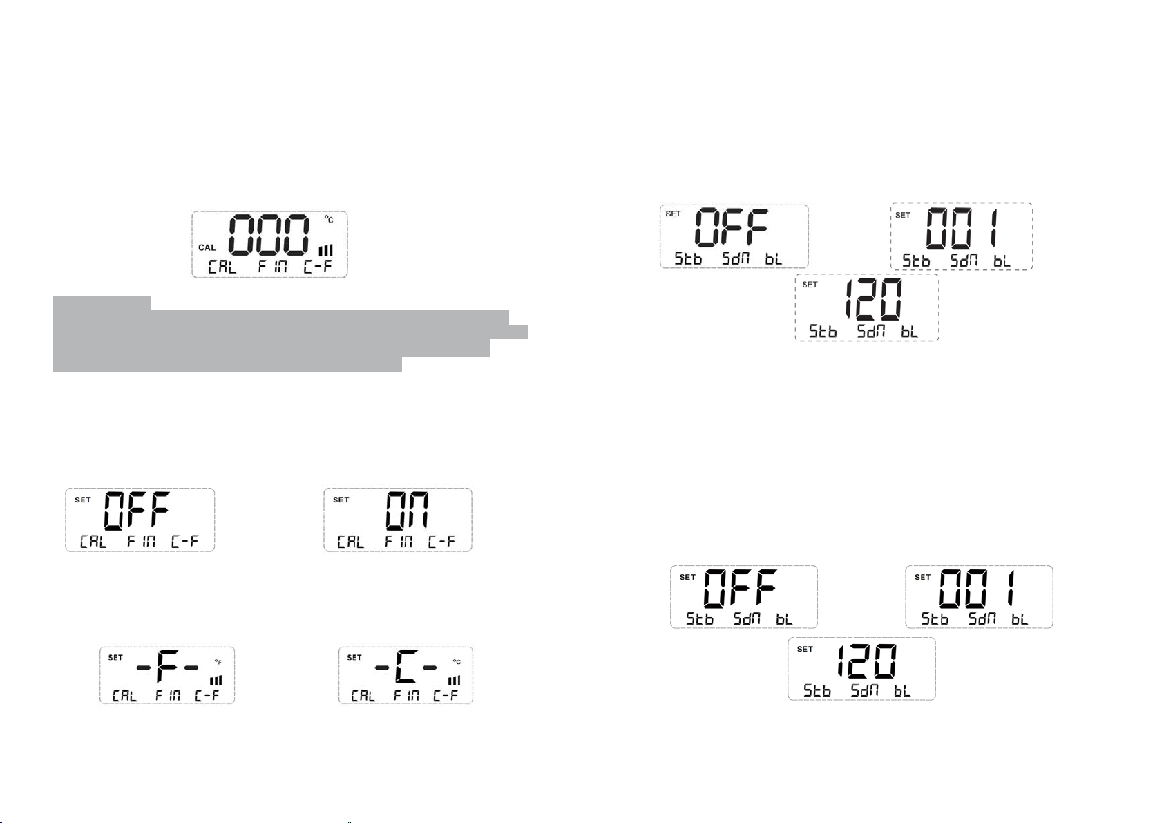
7.Manuallytemperaturecalibration
7.1Infirstsystemsettingpage,press1toentertemperaturecalibrationmode,and"CAL"willshow
ondisplaypanelonwhichalsoshowslastcalibrationvalue(Figure10,calibrationvalueis0Ć).
7.2Incalibrationmode,pressŸandźtosetcalibrationtemperaturevalueswhoserange
isͲ50Ć
~50ĆἷͲ90ȯ~+90ȯἸ.CalibrationvaluewillbenegativeasactualͲmeasuredtemperaturevalueis
smallerthanthevalueshowedondisplaypanel.Calibrationvaluewillbepositiveas
actualͲmeasuredtemperaturevalueisbiggerthanthevalueshowedondisplaypanel.
7.3Press#1tostore
calibrationtemperaturevaluesafterinputcalibrationvalues.
standͲbytimesettingmodeanddisplaypanelwillshowcurrentstandͲbytime.PressźorŸtoset
standͲbytimeandpress#1tosaveit.
Note:StandͲbytimecanbesetbetween1minuteand120minutesandstandͲbyfunctionwillbe
disabledassetting
contentis"OFF"(Figure15).AfterenablingstandͲbyfunction,solderingstation
willenterstandͲbystateifnosolderingworkoranyothercontrolpaneloperationstakenthroughout
duringstandͲbytime,andthetemperaturewilldeclineto150
Ć
andbestabilizedaround150Ć.In
standͲbystate,pickingsolderironhandleoranyoperationoncontrolpanelcanwakeupsoldering
stationandsolderingstationwillcontinuetoworkinpresettemperaturevalue.
Figure10
Calibrationmethod:
Pleasepreparetemperatureprobe,measuresolderingtiptemperatureandrecordit(Pleaseadd
somesolderonsolderingtiptoletsolderingtipandprobecontactclosely).Denoteactualmeasured
temperatureasT1(like320Ć)anddenotedisplayedtemperaturevalueasT2(like350Ć).So
calibrationvalueshouldbeͲ30ć(T1ͲT2)andthenpressźtoinput"Ͳ30".
8Trimmingfunctionisturned8.Enablefinetuning.
8.1Insystemsettingmode,press#2toenterfinetuningsettingmodeanddisplaypanelwillshow
currentfinetuningstatusnow.PressźorŸtoenableordisablefinetuningfunctionandthen
press#2tosaveit.
settingcontentis"ON”,thefinetuningfunctionisturnedonwhichmaketemperature
Note:As
adjustedat1digitforeachpressing.Otherwise,temperaturewillbeadjustedat5digitsforeach
pressing.Thisisquitefitfordifferentoperationrequirements.
Figure11 Figure12
9.Switchingtemperaturescales
9.1In
systemsettingmode,Press#3toentertemperaturescalessettingmodeanddisplaypanel
willshowcurrenttemperaturescalenow.PressźorŸtoswitchtemperaturescalesbetween
FahrenheitandCelsius,thenpress#3tosaveit(Figure13,Figure14).
Figure15 Figure16
Figure17
11.Settingautomaticshutdowntime
a) Insystemsettingmode,pressźtogotosecondsettingpage(Figure8).Thenpress#2toenter
shutdowntimesettingmodeanddisplaypanelwillshowcurrentshutdowntimesetvalue.
PressźorŸtosetshutdowntimeas1minute~120
minutesorOFFandpress#2tosaveit.It
willdisableautomaticshutdownfunctionassettingcontentis"OFF".
Note:AutomaticshutdownfunctiononlycanbeenabledasautomaticstandͲbyfunctionseton.
Solderingstationwillentershutdownstate,stopheatinganddon'tturnoffdisplaypaneluntil
temperaturehasdeclinedto100Ć asthetimeinstandͲbystateexceedspresetshutdowntime.
Afterenteringshutdownmode,anyoperationoncontrolpanelwillmakenosenseafter
enteringshutdownmode.Thesolderingstationonlycanexitthismodeafteruserswitchpower
offandrestartit.
b) Inshutdownmode,solderingstation
isnotinrealpowerͲoffstatewhichstillconsumeslittle
energyassolderingstationiswellconnectedwithpowersupply.Toensuresafety,pleaseturn
offpowerswitchorpullpowerplugout.
Figure18 Figure19
Figure13 Figure14
10.SettingautomaticstandͲbytime
10.1Insystemsettingmode,pressźtogotosecondsettingpage(Figure8).Thenpress#1toenter
7
Figure20
12.Touc hto n efunction
12.1Insystemsettingmode,pressźtogotosecondsettingpage(Figure8).Thenpress#3toenter
8
 Loading...