

Page 1
GT
compatible
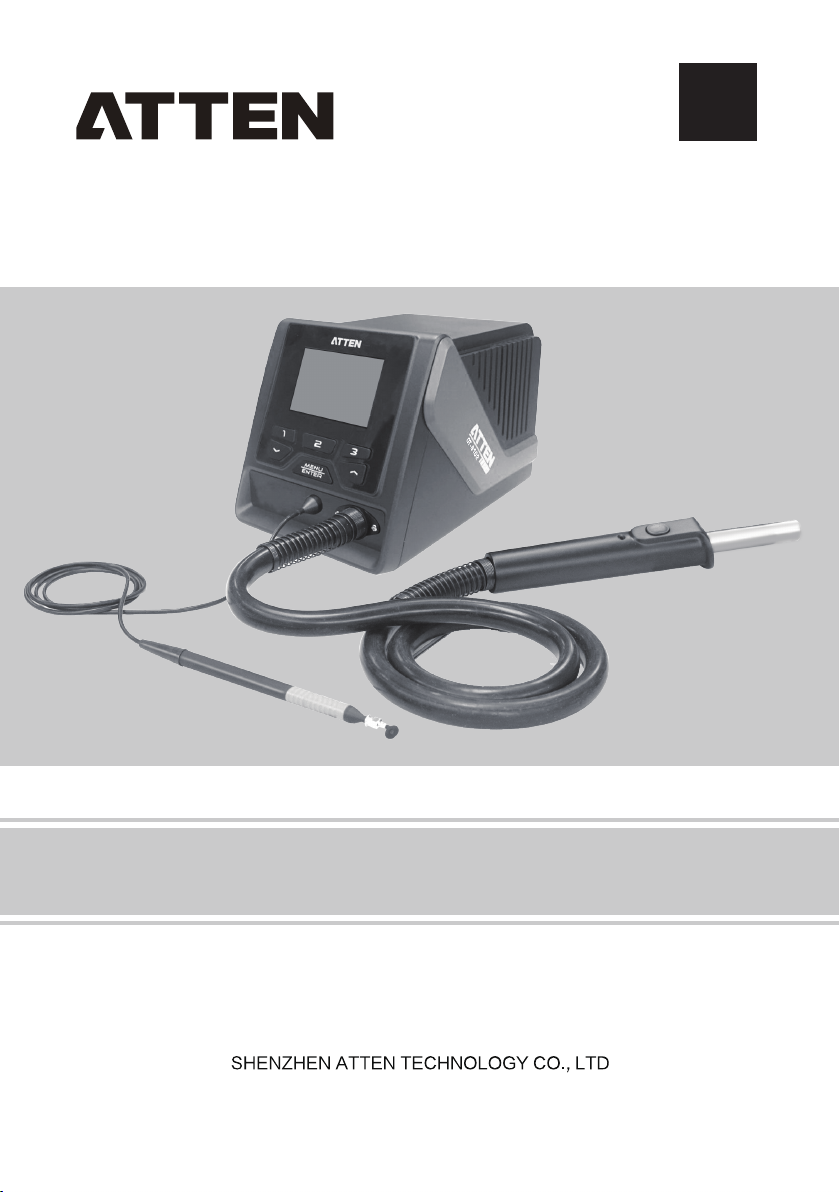
GT-8102 Hot Air Desoldering Station User Manual
Page 2

Page 3

Contents
Copyright information
Description of common symbols
Essential knowledge for users
Safety precautions ..
Disclaimer
Packing list
Schematic diagram of the whole equipment
Connection steps for the whole equipment
Technical parameters .. .....................................................................6
Description of normal working interface .............................................7
Selection method of working interface ................................................7
Operations of air volume / temperature setup
Call of quick air volume / quick temperature .......................................8
Enabling / Disabling of vacuum pen function ......................................9
Use method of vacuum pen ...............................................................9
Parameter setup
System setup menu ....
Host system setup parameters
Total items of function setup menu
Diagram of keypad functions in curve mode
Curve working interface
Care and maintenance ....................................................................22
Product warranty
After-sales contact
Appendix
Product warranty card
........................................................................................2
........................................................................................3
.........................................................................................24
........................................................................2
........................................................2
...........................................................2
..........................................................................2
.......................................4
.........................................4
....................................8
...............................................................................9
.....................................................................10
........................................................11
..................................................14
....................................17
...................................................................17
............................................................................23
........................................................................23
.....................................................................25
1
Page 4
Copyright information
The design of this product (including internal software) and its accessories is under the protection of
relevant state laws. Any infringement upon the relevant rights of our company will be subject to legal
sanctions. Users shall consciously abide by the relevant state laws when using this product.
Description of common symbols
Thank you for using our products. Before using the product, please read this manual carefully and pay
attention to the relevant warnings and cautions mentioned in this manual.
Warning Misuse of this product may lead to serious injury or death to the user.
Caution Misuse of this product may lead to serious injury to the user or material damage to
the object involved.
Essential knowledge for users
Users are required to have basic knowledge of common sense and electrical operations before using
the product.Minors shall use the product under the guidance of a professional or guardian.
[Caution]: To avoid damaging the equipment and keep the safety of the operational environment,
please read this manual carefully before use and keep it well so that you may read it at any time
when necessary.
Safety precautions
To avoid electric shock or injury to the human body or fire hazard, the following basic rules must be
observed when using the equipment. In order to ensure personal safety, only parts and accessories
approved or recommended by the original factory can be used, otherwise, serious consequences may
occur!
Warning
When using this product, the spray nozzle of hot air gun, with the temperature up to 100-480℃, may
cause burns to the user or cause a fire due to improper application. So Users shall strictly observe
the following rules:
● Keep this product away from flammable materials.
● Keep the product out of children's reach.
● Do not use this product if you are inexperienced or have no sufficient necessary knowledge
without the guidance of related personnel.
● Do not use this product under wet environment or with wet hands to avoid electric shock.
● Do not modify this product or its accessories without authorization.
● Please turn off the power when replacing parts and iron tips, and do not resume the use until
the equipment is completely cooled down.
● Please use the accessories from the original factory when replacing the product parts.
● Make sure to turn off the power switch when the equipment is temporarily stopped or out of use.
● To ensure the normal operation of this product’s ESD function, only three-core power cord
shall be used as the host connecting line.
● Do not play or do other similar dangerous actions when using this equipment, because it can
easily lead to injury to others or yourself.
● Do not use this product for purposes other than de-soldering.
● Do not modify this product and its accessories, otherwise the original warranty will be invalidated
or damage may occur to the product.
● When plugging and unplugging the power cord and handle plug, please hold the plug body and
do not pull the cord.
● Do not hit the product or its accessories too hard during the operation; otherwise damage may
occur to the product.
Caution
Disclaimer
We will take no responsibility for any personal injury or property damage caused by reasons other than
the product quality problem, which may include force majeure (natural disasters, etc.) or personal
behavior during the operation of this product.
This manual is organized, compiled and released by SHENZHEN ATTEN TECHNOLOGY CO., LTD.
according to the latest product features. We will not be responsible for further notice of the subsequent
improvement of the product and this Manual.
2
Page 5
Packing list
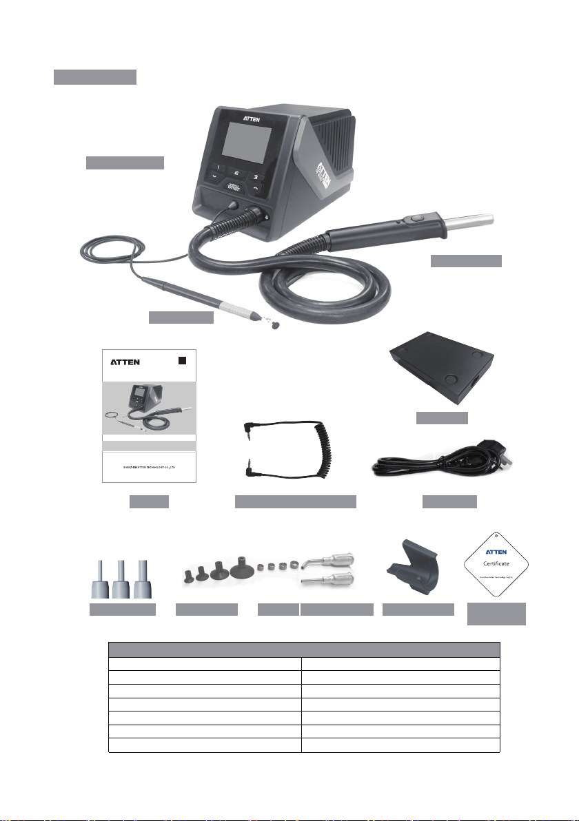
GT-8102 host
GT-8102 hot air desoldering station user manual
Vacuum pen
GT
compatible
Hot air handle
Tool box
Manual
Suction disc Spring Suction nozzle
GT-8102 packing list
GT-8102 host
Operating manual
Power line
Handle holder
Spray nozzle
Suction disc
Spring
1 Set
1 Set
1 Pcs
1 Pcs
3 Set
4x3 Pcs
4 Pcs
Vacuum pen
Hot air gun handle
Conformity certificate
Double-male-connector
Tool box
Suction nozzle
3
Power lineDouble-male-connector
Handle holderSpray nozzle
Conformity
certificate
1 Set
1 Pcs
1 Set
1 Pcs
1 Set
2×2 Pcs
Page 6
Schematic diagram of the whole equipment
4
3
USE ONLY WITH 250V FUSE
5 2 8 967 10 111213
1
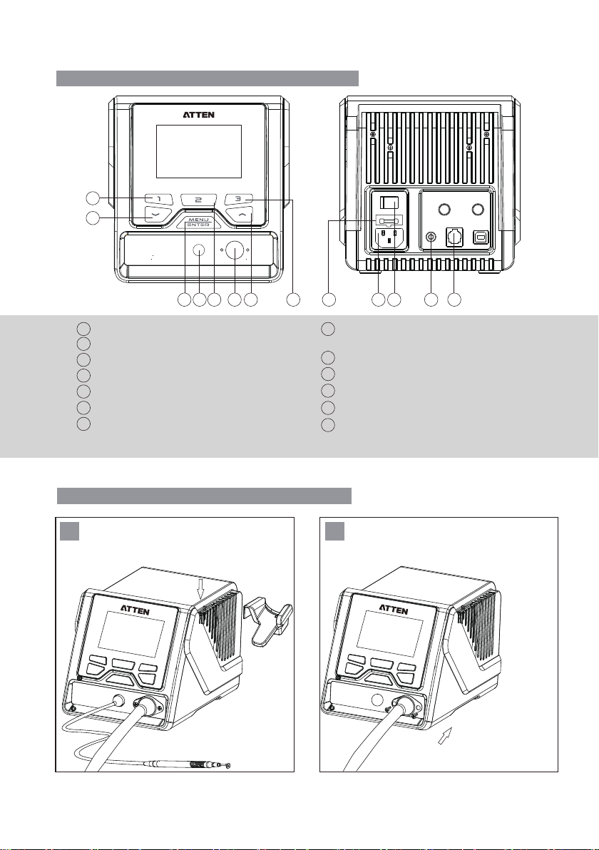
Hot air handle interface
2
Vacuum pen interface
3
Down arrow key /minus key
4
Rapid temperature key 1
5
Confirm key / Menu key
6
Up arrow key / plus key
Rapid temperature key 2 / Vacuum pen
7
switch reuse key / System setup menu
switching key
1
8
9
10
11
12
13
Connection steps for the whole equipment
1
Install the dormancysupport
2
Rapid temperature key 3 / System setup
menu switching key
Power plug, connected to rated AC power
Power master switch
RS232 communication interface
Handle holder interface
Power fuse
Install the hot air handle
4
Page 7
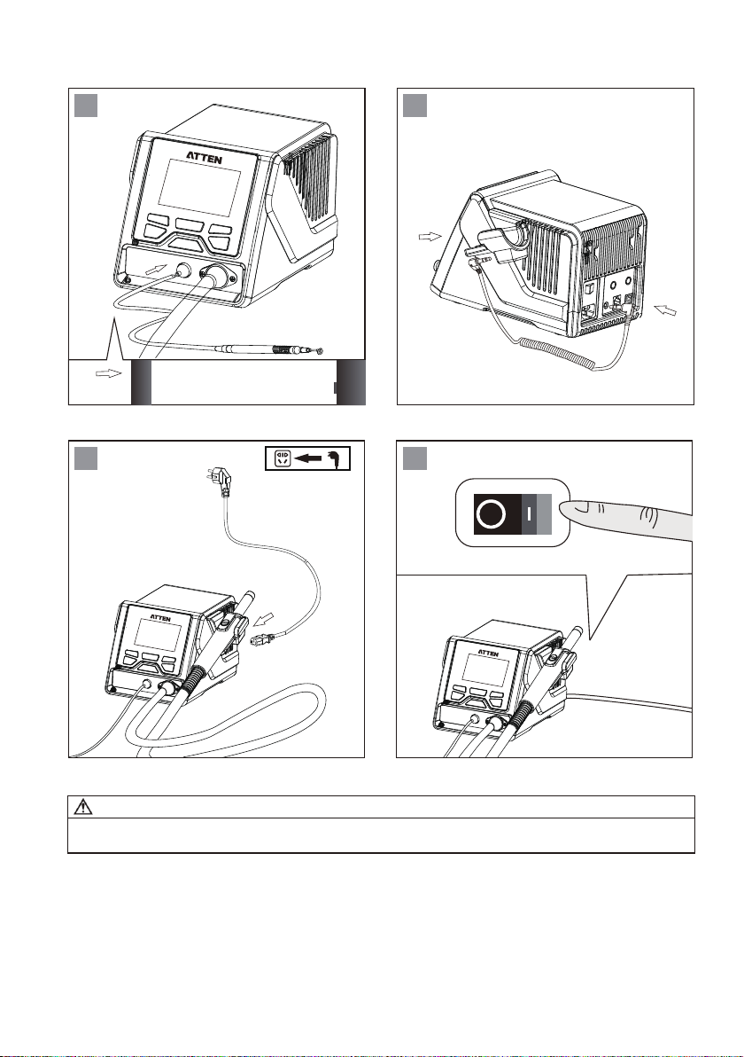
3
Connect the vacuum pen
4
Connect to the signal line of dormancy
switch(With dormancy function, thus
ensuring effective use of products and
energy-saving.)
Connect the charger
5 6
Warning
When replacing the hot air handle, be sure to turn off the power switch of host, and unplug the power
plug, to avoid electric shock.
Press power button, and the equipment
can be started or shut down.
5
Page 8

Technical parameters
Product model
Rated operating voltage
Rated power
Power fuses
Setting range of temperature
Setting range of air volume
Timing time
Temperature unit
Hot air flow
Vacuum pressure of
vacuum pen
Cooling function of
standby heater
Heating element
exception detection
Temperature sensor
exception detection
Password protection
function
Alarm function
Quick function
User temperature
compensation
Multiple language for
user interface
Monitor resolution
Monitor contrast
Heating power display
Temperature adjustment
step
Air volume adjustment
step
Rapid temperature / air
volume
Working conditions
Storage conditions
Dimension
GT-8102
AC 230V±10% 50hz (110v±10% 60hz, optional)
1000W(Max)
T 6.3A (230VAC) T 12A (110V AC)
100℃ ~ 480℃/ 212℉ ~ 896℉
25%~99%
10~900S
℃/℉; ℃ by default
120L(Max)
-80Kpa
Supported
Heating element removal detection; heating element open
circuit detection; heating element overheating detection
Sensor open circuit detection
Available (Disabled by default)
Available (Enabled by default)
Three groups of rapid temperature
±50℃ /±90℉
Support Chinese / English interface;
Chinese interface by default
240x160 Dots(white letters on blue)
10~100%
Five dynamic power bars
Long press and the temperature will be adjusted at a step
of 10 units; momentarily press, and the temperature will
Long press and the air volume will be adjusted at a step
of two units; momentarily press, and the air volume will
Temperature 0℃~40℃ Relative humidity<80%
Temperature -20℃~80℃ Relative humidity<80%
be adjusted at one unit.
be adjusted at one unit.
3 groups of temperature / air volume,
which can be called quickly
315(L)×252(W)×127(H)mm
Approximately 4kgWeight
6
Page 9
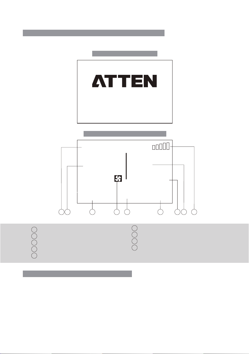
Description of GT-8102 normal working interface
Aften connected with charger turn on the power switch. the product will be working normally.
Aften the screen display systen version for 3 seconds.
GT-8102 startup interface
GT-8102 normal working interface
Standby
50
50% 50% 50%
200 300 400
1 6 743
2 8 9
1
Status display area.
Display of air volume.
2
3
Rapid temperature / air volume 1.
Air volume setting icon.
4
5
Rapid temperature / air volume 2.
8102
%
Vers io n: 1.00
ww w.atten. com
---
o
300
5
6
Rapid temperature / air volume 3.
7
Display area of preset temperature.
8
Display of actual temperature.
9
Heating power strength display.
c
Selection method of working interface
1. Long press “MENU” key to enter the system setup interface;
2. Short press the shortcut key “3” to enter the function setup interface (short press the shortcut
key “2” to jump to the system setup interface);
3. Select the interface mode (normal / curve);
7
Page 10
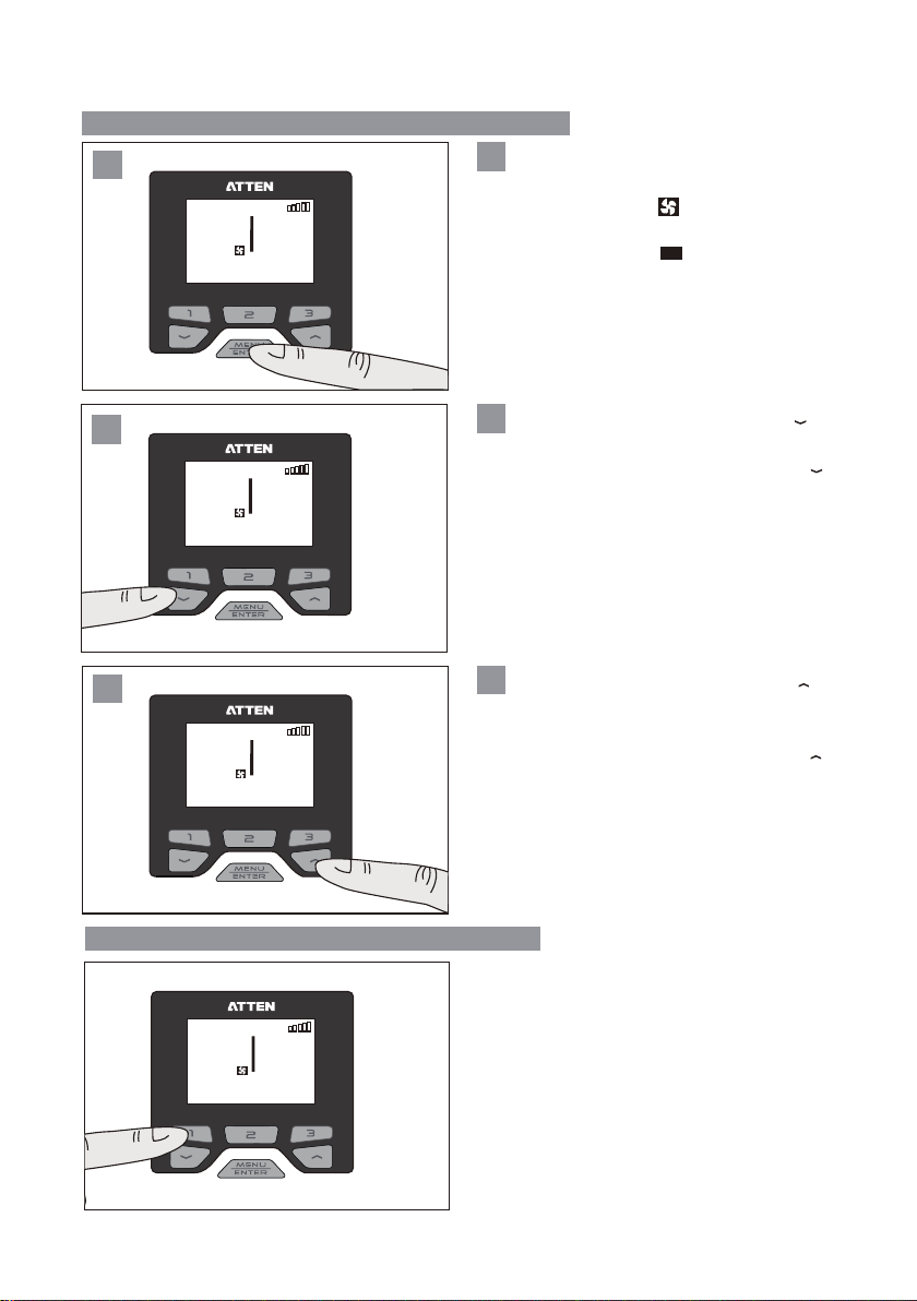
Operations of air volume / Temperature setup
1
1
Standby
---
33
%
o
c
29% 45% 99%
380 410 480
200
2
Standby
---
32
%
o
c
29% 45% 99%
380 410 480
200
1
Standby
---
33
%
o
c
29% 45% 99%
380 410 480
200
Short press “MENU” key to switch the air
volume setup and temperature setup.
If selecting the icon , it means setting the
air volume.
If selecting the icon ℃, it means setting
the temperature.
2
When setting the air volume, press “ ” and
the air volume will drop (drop to 25% at most).
When setting the temperature, press “ ”
and the temperature will drop (drop to 100℃ at
most).
3
When setting the air volume, press “ ” and
the air volume will increase (increase to 99% at
most).
When setting the temperature, press “ ”
and the temperature will rise (rise to 480℃ at
most).
200
Call of quick air volume / quick temperature
Short press “1” (“2” or “3”), and the
corresponding quick temperature value and air
Standby
---
33
%
29% 45% 99%
380 410 480
200
o
c
volume value can be called.
Note: The quick air volume value / temperature
value can be changed and set in the function setup
menu.
Default status:
Quick 1 temperature / air volume: 200℃/50%.
Quick 2 temperature / air volume: 300℃/50%.
Quick 3 temperature / air volume: 400℃/50%.
8
Page 11
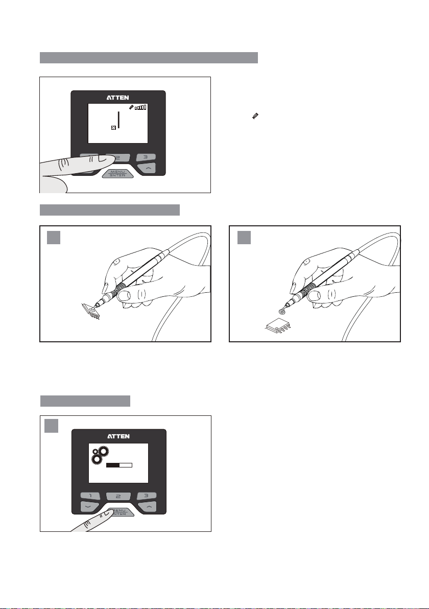
Enabling / Disabling of vacuum pen function
50%50%
In the normal working interface:
1. Long press the key “2” for 2sec, the
Standby
---
33
%
29% 45% 99%
380 410 480
200
o
c
vacuum pen function can be enabled, and the
icon “ ” will be displayed.
2. Then long press the key “2” again and the
vacuum pen function will be disabled.
Use method of vacuum pen
1 2
When the vacuum pen function is enabled, the
vacuum pen can be operated.
Block the air hole of vacuum pen with the finger,
and the SMD components can be sucked in.
Parameter setup
1
Load ing.. .
Loosen the air hole, and put down the components.
Hold "MENU" key until the load is completed
(100%).
9
Page 12
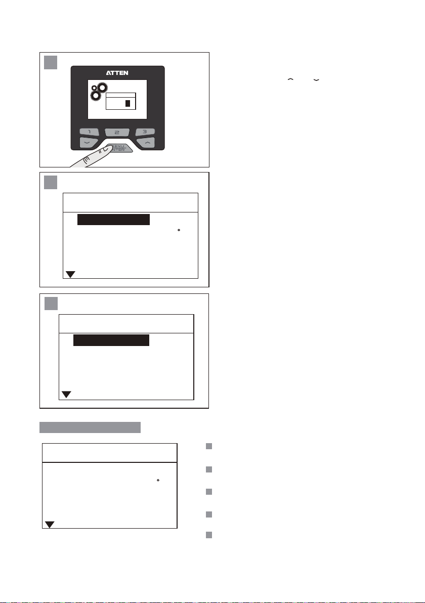
2
If the configuration page is under the protection of
password, the login to “Confirm” page shall be
authorized. Press " " or " " key to change the
Login
* *
9
Exit
input value, press “Enter" key to complete one
input, and press the key "3" to return to the main
interface.
3
System set
Languages
Unit
Password
Keypad Tone
LCM Contrast
4
Function set
UI Mode
Temp Offset
Timing Work
Shortcut Tmep 1
Shortcut Air 1
System setup menu
System set
Languages
Unit
Password
Keypad Tone
LCM Contrast
En
C
* * *
ON
4 4
Nor
4
10
100
30
En
C
* * *
ON
4 4
If there is no password protection, or after the
correct password is entered, it will jump to the
system parameter setup interface. At this time,
the system parameters can be configured.
Press the key “3” to enter the function setup page.
Press the key “2” to enter the system setup page.
Languages
: Language displayed on the system
and menu.
Unit
: Temperature unit displayed
on the system.
Password
: The authorization password set to
enter the system parameters interface.
Keypad Tone
: The switch to turn on and off
the key operation tone.
LCM Contrast
: Contrast ratio adjustment
displayed on the screen.
10
Page 13
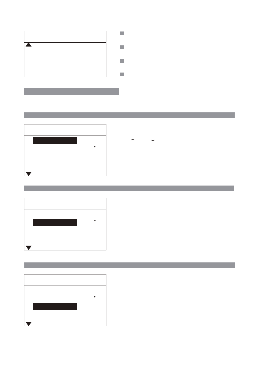
Mode
System set
Mode
Net Address
Factory Default
Exit
Nor
1
: Used to define the Host communication (not
available yet).
Net Address
during networking operation (not available yet).
Factory Default
factory settings.
Exit
: Press to exit the parameter setup to return to
the main interface.
: Local communication address defined
: Used to resume the Host to the
Host system setup parameters
In any setup mode, press the key “3” to enter the function / curve setup page;
press the key “2” to enter the system setup page.
Languages
System set
〉
Languages
System set
Languages
Unit
Password
Keypad Tone
LCM Contrast
Unit
System set
Languages
Unit
Password
Keypad Tone
LCM Contrast
Password
System set
Languages
Unit
Password
Keypad Tone
LCM Contrast
En
C
* * *
ON
4 4
En
C
* * *
ON
4 4
En
C
* * *
ON
4 4
Used to set the system language:
Short press the “MENU” key to enter the language option;
Press “ ” or “ ” to switch the language.
EN: English.
CN: Chinese.
After selecting the required language, short press the
“MENU” key to confirm it.
The factory default is: Chinese.
System set
Used to set the system temperature unit:
℃: Celsius.
℉
: Fahrenheit.
The factory default is: ℃.
System set
1. Used to lock the system and protect set
parameters of the system from being changed
by unauthorized person.
2. Coordinate with the fixed temperature of
parameter setup of the function, lock the
temperature of the whole equipment and
control the welding process.
The factory default is: OFF.
〉
Password
〉
Unit
11
Page 14
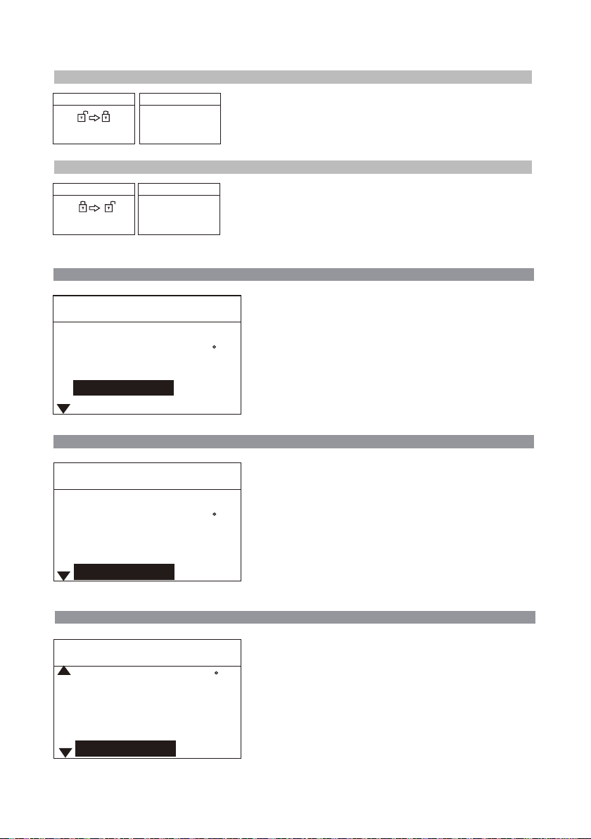
System lock-in
Enter PIN
0 -
-
System lock
PIN:
000
System set
Under the password setup state, enter a three-digit password,
and display the prompt locked by the system. Press Enter to
return to the password setup.
〉
Password
〉System lock-in
System lock-out
Enter PIN
0 - -
System unlock
Password error
Enter the correct password, the system is unlocked and the
password is cancelled;
Enter the incorrect password, and wrong password will be
reminded.
System set
〉
Password
〉System lock-out
Keypad Tone System set 〉Keypad Tone
System set
Languages
Unit
Password
Keypad Tone
LCM Contrast
LCM Contrast
System set
Languages
Unit
Password
Keypad Tone
LCM Contrast
En
* * *
ON
En
* * *
ON
Used to open or close the prompt tone for key
operation:
Open (ON): Prompt tone is given for key operation.
Close (OFF): Prompt tone is not given for key operation.
C
The factory default is: ON.
4 4
System set 〉
Used to set the contrast ratio of the display screen:
10: Minimum contrast ratio.
100: Maximum contrast ratio.
The factory default is: 44.
C
4 4
LCM Contrast
Mode
System set
Unit
Password
Keypad Tone
LCM Contrast
Mode
Used to set the product communication mode:
Normal: Close the communication function.
C
Host / Slave: Used for function extension.
The factory default is: normal.
* * *
(The function has not been open)
ON
44
Nor
12
System set 〉Mode
Page 15
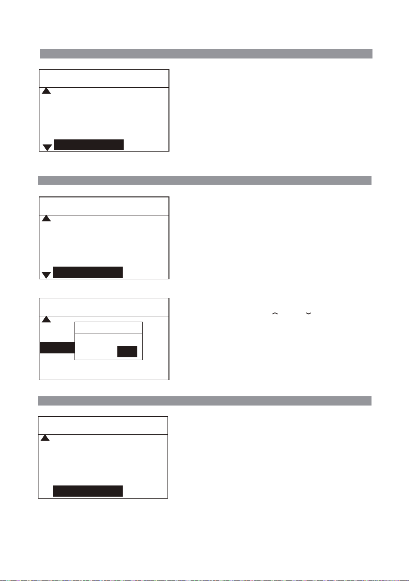
Net Address
System set 〉Net Address
System set
Password
Keypad Tone
LCM Contrast
Mode
Net Address
Factory Default
System set
Keypad Tone
LCM Contrast
Net Address
Factory Default
System set
Mode
Net Address
Factory Default?
Factory Default
NO
Exit
Reset
YES
* * *
ON
414
Nor
ON
44
NorMode
1
Nor
1
Used for communication among many machines and
can be connected to 255 devices at most:
Adjustment range: 1~255 (used for function extension).
The factory default is: 1.
(The function has not been open)
System set 〉Factory Default
Used to restore system parameters to factory default.
After the factory default is restored through click
confirmation, all system parameters will be restored to
factory default.
Reset the dialog box:
Select the function using “ ” or “ ” and press
Enter to execute this function.
Exit
System set
LCM Contrast
Net Address
Factory Default
Exit
44
NorMode
1
System set 〉Exit
Used to exit from parameter setup and return to the
main interface.
All parameters changed will be stored upon exit, and
will apply.
13
Page 16

Total items of function setup menu
In any setup mode, press the key “3” to enter the function / curve setup page,
and the key “2” to enter the system setup page.
Function set
UI Mode
Temp Offset
Timing Work
Shortcut Tmep 1
Shortcut Air 1
Nor
4
10
100
30
UI Mode: Used for switching among interface modes.
Temp Offset: Used to compensate the error of temperature
output.
Timing Work: Used to set the timed heating work.
Shortcut Tmep 1: Set temperature 1for user’s quick
call.
Shortcut Air 1: Set air volume1for user’s quick call.
Function set
Shortcut Tmep 2
Shortcut Air 2
Shortcut Tmep 3
Shortcut Air 3
Temp Upper
Function set
Temp Lower
Temp Lock
Exit
Function setup menu
UI Mode
Function set
UI Mode
Temp Offset
Timing Work
Shortcut Tmep 1
Shortcut Air 1
410
45
480
99
480
100
OFF
Nor
4
10
100
30
Shortcut Tmep 2: Set temperature 2 for user’s quick
call.
Shortcut Air 2: Set air volume2 for user’s quick call.
Shortcut Tmep 3: Set temperature 3 for user’s quick
call.
Shortcut Air 3: Set air volume 3 for user’s quick call.
Temp Upper: The maximum temperature that
can be set by the user in the main working interface.
Temp Lower: The minimum temperature that
can be set by the user in the main working interface.
Temp Lock: A temperature value set to prevent
user from adjusting the operating temperature during the
use, so as to ensure the hot air gun is working at the
constant temperature.After this function is started, the
output temperature stays at the set temperature value.
Exit: Exit the function setup interface.
Function set
UI Mode: Used for switching among interface modes.
Contain “Normal” and “Curve” two modes.
Normal mode: Display the interface in text format.
Curve mode: Display the interface in reflow curve format.
〉
UI Mode
14
Page 17

Temp Offset
Function set
UI Mode
Temp Offset
Timing Work
Shortcut Tmep 1
Shortcut Air 1
Note: If the user discovers that the temperature is inaccurate when replacing the heating core or the handle, it can
be corrected through parameter modification as follows:
1. Set the handle temperature to be corrected at a suitable value, e.g. 350℃/662℉.
2. After the temperature remains stable, test the actual temperature of the current handle air outlet using
temperature tester, e.g. the actual temperature is 365℃/689℉.
3. The actual temperature is 15℃/27℉higher than the set temperature when a conclusion is drawn through
analysis.
4. Set the temperature compensation value as -15℃/-27℉, that is, compensate for the output temperature error.
Nor
4
10
100
30
Used to compensate for the temperature output error o
hot air gun.
Compensation range: -50℃~+50℃, -90 ℉ ~+90 ℉.
In case of a positive value, the hot air gun temperature
will increase to the set value.
In case of a negative value, the hot air gun temperature
will decrease to the set value.
The factory default is: 0.
Function set 〉Temp Offset
Timing Work
Function set
UI Mode
Temp Offset
Timing Work
Shortcut Tmep 1
Shortcut Air 1
Shortcut Tmep 1
Function set
UI Mode
Temp Offset
Timing Work
Shortcut Tmep 1
Shortcut Air 1
Shortcut Air 1
Function set
UI Mode
Temp Offset
Timing Work
Shortcut Tmep 1
Shortcut Air 1
Nor
4
10
100
30
Nor
4
10
100
30
Nor
4
10
100
30
Function set
Used to set the timed heating time of product, and after
pressing the handle switch, it will start to work and count
down and when the timing is finished, close the heating.
Off: The timing function is closed.
10-900: Open the timing function; the timing time unit is“S”.
When there is 10sec countdown, there will be a prompt tone
“D” once.
The factory default is: Off.
Function set
3 sets of data of set temperature for users’ quick call:
The factory default is:
Quick temperature 1: 200℃/392℉.
Quick temperature 2: 300℃/572℉.
Quick temperature 3: 400℃/752℉.
Function set
3 sets of data of set air volume for users’ quick call:
The air volume value is 25%-99%.
The factory default is: 50%.
〉
Timing Work
〉
Shortcut Tmep 1
〉
Shortcut Air 1
15
Page 18

Function set
Function set 〉Temp Upper
Function set
Shortcut Tmep 2
Shortcut Air 2 45
Shortcut Tmep 3 480
Shortcut Air 3
Temp Upper
Temp Lower
Function set
Shortcut Air 2 45
Shortcut Tmep 3 480
Shortcut Air 3
Temp Upper
Temp Lower
410
99
480
99
480
100
The maximum temperature that can be set by the user in
the main working interface.
The set maximum temperature is 480℃/896℉.
The set minimum value of the “maximum temperature”
should be no less than or equal to the “minimum
temperature”.
The factory default is: 480℃/896℉.
Function set 〉Temp Lower
The minimum temperature that can be set by the user in
the main working interface.
The set minimum temperature is 100℃/212℉.
The set maximum value of the “minimumtemperature”
should be no greater than or equal to the “maximum
temperature”.
The factory default is: 100℃/212℉.
Temp Lock Function set 〉Temp Lock
Function set
Shortcut Tmep 3 480
Shortcut Air 3
Temp Upper
Temp Lower
Temp Lock OFF
Exit
99
480
100
After this function is enabled, the handle temperature stays
at the set temperature. The set fixed temperature is not
limitedto “maximum temperature” and “minimum
temperature”.
OFF: Temperature lockout function is off.
100-480℃/212-896℉: Temperature lockout is started, the
handle works at the fixed temperature, and the user cannot
change the set temperature in the main interface.
The factory default is: OFF.
Function set
〉Exit
Function set
Shortcut Air 3
Temp Upper
Temp Lower
Temp Lock
Exit
99
480
100
OFF
Used to exit from parameter setup and return to the main
interface.
All parameters changed will be stored upon exit and will
apply.
16
Page 19
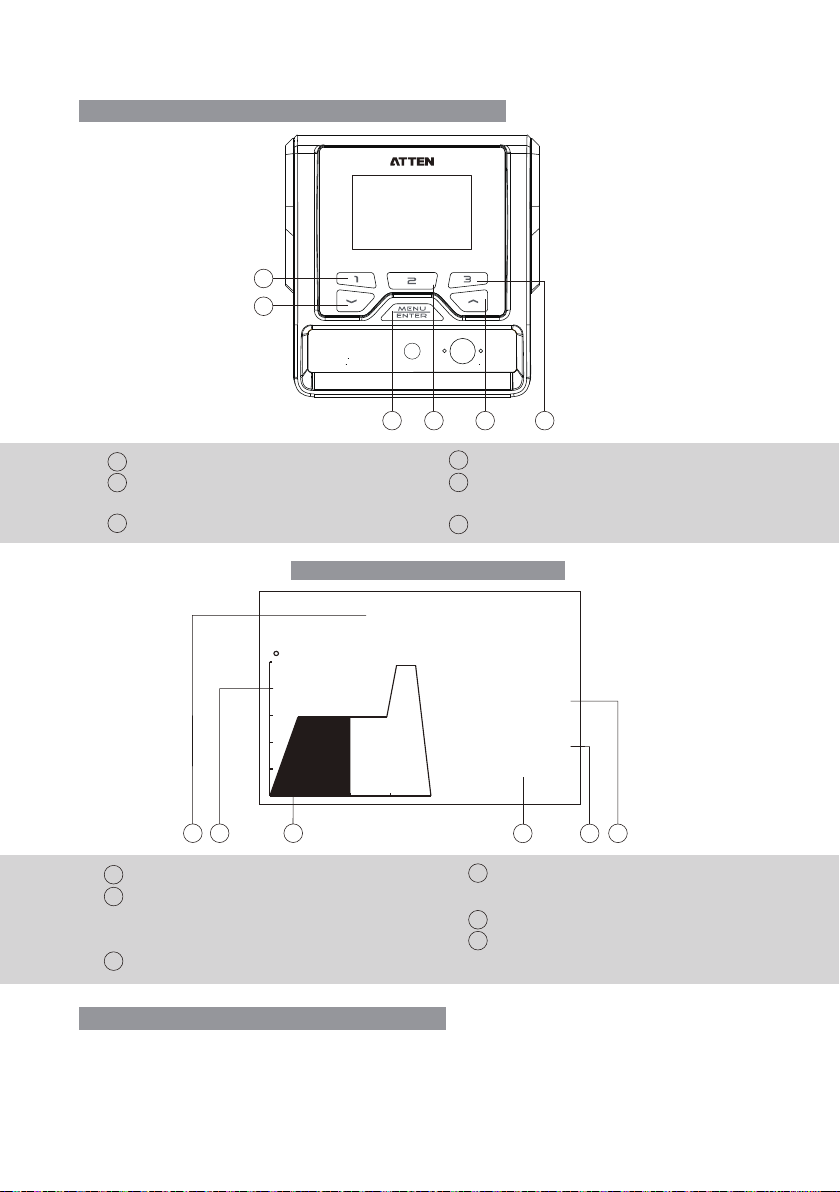
Diagram of keypad functions in curve mode
1
4
5 362
Curve number minus
Shortcut key of curve 1
1
Shortcut key of curve 2; long press to
2
run the vacuum pen function
Shortcut key of curve 3
3
GT-8102 curve working interface
4
Short press to run the curve; long press
5
for curve setup
Curve number plus
6
Profile
C
1
Temp ℃
301
Air
Time 103 s
1
2
Current working curve number (1-25)
1
Temperature scale; one division is 100℃ (500℃
2
/932℉(Max)); if the temperature is lower than
100℃/212℉, the heating will be closed.
3
Time axis (1-600S).
3
Selection method of working interface
1. Lon press “MENU” key to enter the system setup interface;
2. Short press the shortcut key “3” to enter the curve setup interface (short press the shortcut key
“2” to jump to the system setup interface);
3. Select the interface mode (normal / curve);
17
50%
4
4
Current remaining countdown time of curve
operation.
Set air volume value of current node.
5
Actual temperature display.
6
6
5
Page 20
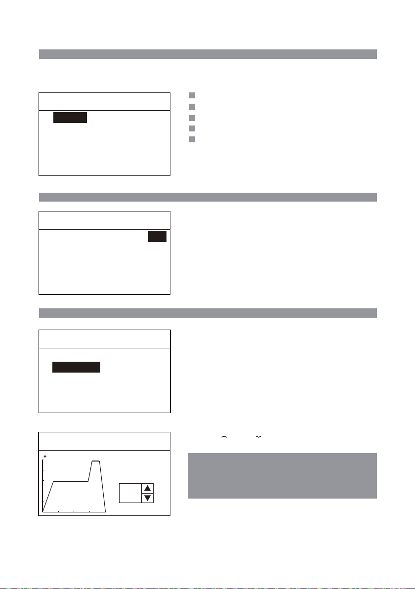
Total items of curve setup menu
In any setup mode, press the key “3” to enter the function / curve setup page;
press the key “2” to enter the system setup page.
Profile Setup
UI Mode
Edit Profile
Copy Profile
Pro
UI Mode: Current working mode is curve mode.
Edit Profile: Change the set curve parameters.
Copy Profile: Copy the existing curve.
Delete Profile: Delete the curve not needed.
Exit: Exit the curve setup mode.
Delete Profile
Exit
UI Mode
Profile Setup
UI Mode
Edit Profile
Copy Profile
Pro
Interface mode: Used for switching among the interface
modes.
Contain “normal” and “Curve” two modes.
Normal mode: Display the interface in text format.
Curve mode: Display the interface in reflow curve format.
Delete Profile
Exit
Edit Profile
Profile Setup
UI Mode
Pro
Hold “MENU” key to enter the Edit curve.
Edit Profile
Copy Profile
Delete Profile
Exit
Profile Setup
Profile Setup 〉Edit Profile
〉UI Mode
Edit Profile
C
Selet
Profile
1
Press “ ” or “ ” key to select the curve to be
edited.
The default curve 1-3 has been set when leaving the
factory (the user can edit it);
After restoring the factory default, the curve 1-3 will
be restored to the factory default.
18
Page 21
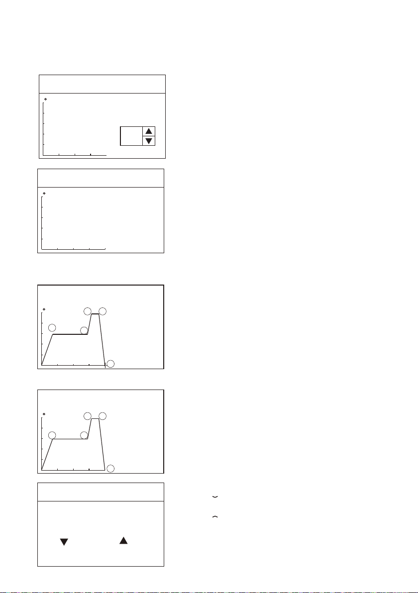
For example: select Edit curve 4, and it needs to press “MENU” key again to enter Edit curve 4
(the default is empty curve).
Edit Profile
C
Empty
Profile
Selet
Profile
4
Edit Profile
C
Empty
Profile
Edit Profile4
Add curve node
Profile 4
C
1
Delete curve node
3
2
Profile 4
C
1
2
4
43
4
5
5
Step 1
Time Temp Air -
Exit
Step 5
Time Temp Air -
Exit
Step 5
Time Temp Air -
Exit
Step: Operational step during the operation of hot air handle
(at most nine steps).
Time: Time of current operational step during the operation of
hot air handle.The total time of all steps is 600S at most.
Temperature: Operating temperature during the operation of
hot air handle.(100-480℃; closed when the temperature is
lower than 100℃)。
Air volume: Air volume during the operation of hot air handle
(25-99).
Note: Next step can be set only after three parameters of time,
temperature and air volume are set.
Operational steps of adding node:
As shown in the left figure:
Add one node to the curve 4,
After the time, temperature and air volume are set in Step 5,
confirm and save it.
Note: The node can be only added after the final node, and
after a node is added, a node blinking cursor will appear.
Operational steps of deleting node:
As shown in the left figure:
Add one node from the curve 4,
Reduce the time to zero at Step 5, and the node 5 is deleted.
Note: Only the node of the final step can be deleted.
Edit Profile
Save changes?
No Yes
After editing the curve, select Exit, and save the curve.
Press “ ” on the machine panel and the curve will not be
saved.
Press “ ” on the machine panel to save the curve.
19
Page 22
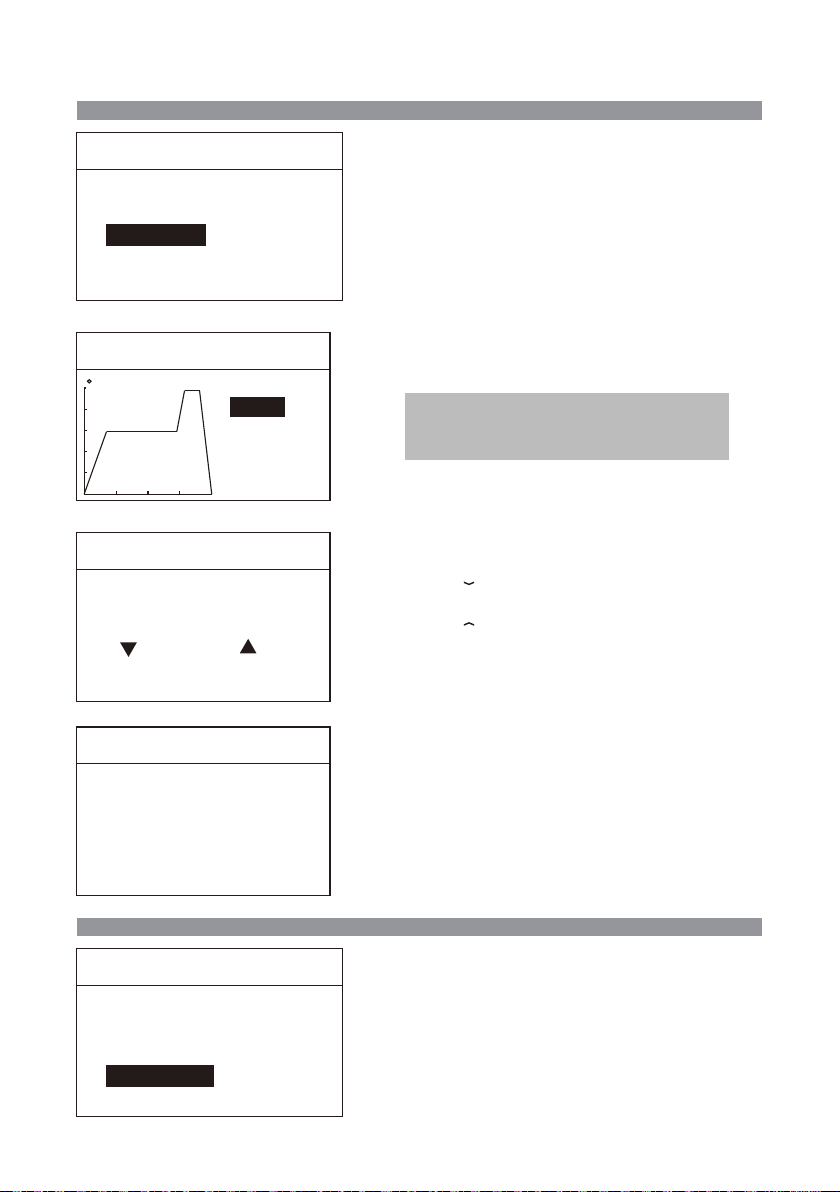
Copy Profile
Profile Setup
UI Mode
Edit Profile
Copy Profile
Delete Profile
Exit
Pro
Profile Setup
Hold “MENU” key to enter the Copy curve.
〉
Copy Profile
Copy Profile
C
Copy Profile
Are you sure?
No Yes
Copy Profile
Profile 1 copied to 7
Source 1
Dest. 7
Exit
Source curve: Curve to be copied.
Target curve: Curve generated after copying.
Exit: Press “MENU” key to copy the curve.
Note: After the source curve is copied to the
target curve, the source curve will replace the
target curve.
After selecting the source curve and target curve,
select Exit,and copy the curve.
Press “ ” on the machine panel and the curve
will not be saved.
Press “ ” on the machine panel to save the
curve.
Finish copying the curve.
Delete Profile Profile Setup
Profile Setup
UI Mode
Edit Profile
Copy Profile
Delete Profile
Exit
Pro
Hold “MENU” key to enter the Delete curve.
20
〉
Delete Profile
Page 23
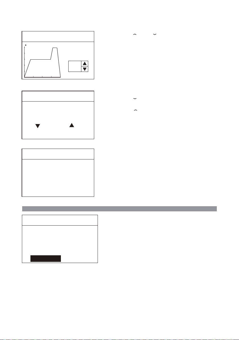
Delete Profile
C
Press “ ” or “ ” on the panel to select the
curve to be deleted.
Selet
Profile
7
Delete Profile
Are you sure?
No Yes
Delete Profile
Profile 7 delete!
Exit Profile Setup〉Exit
Profile Setup
UI Mode
Edit Profile
Copy Profile
Delete Profile
Exit
Pro
After selecting the curve to be deleted,
Press “ ” on the machine panel and the curve
will not be deleted.
Press “ ” on the machine panel to delete the
curve.
Finish deleting the curve.
Hold “MENU” key to exit the curve setup and
enter the running curve.
21
Page 24
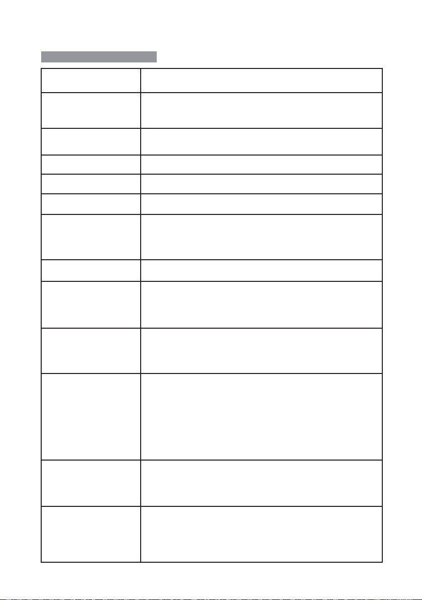
Care and maintenance
Fault code or fault
description
E0: Abnormal fan
E1: Open circuit of heating
core
E2: Open circuit of sensor Poor contact of air gun connector or handle.
E3: No zero-cross signal The zero-cross sensor is damaged or the mains frequency is wrong.
E5: Over-current output Internal short circuit of heating core.
E6: Abnormal voltage
E7: Short circuit of sensor
E8: Over-temperature
protection
E9: Abnormal handle
Screen display fault:
Inaccurate temperature:
Display of messy code:
Likely causes of the faults
1. The fan fails to rotate.
2. The fan sensor is damaged.
3. Poor contact.
1. The heating core is damaged; replace the heating core.
2. The sensor lead is in open circuit; inspect the soldering pencil lead.
1. The external supply voltage is abnormal; please check whether
the product input voltage conforms to the requirements.
2. The product host is damaged; Send the equipment to the
designated after-sales service outlet for maintenance.
The short circuit occurs to the temperature sensor in the
heating core; pleas replace the heating core.
1. The temperature sensor is abnormal; please replace the heating
core.
2. The temperature of heating core is too high; after the heating core i
s cool, restart the machine.
1. The equipment doesn’t support the handle type; please
use the original product.
2.The internal circuit is abnormal; send the equipment to the
designated after-sales service outlet for maintenance.
In case the problem occurs, you can try to adopt the following
measures to solve it.If the problem still cannot be solved, please
return the equipment to the original factory for inspection.
1. Check if the socket switch is on.
2. Check if there is voltage on the socket.
3. Check if the plug with the power line is loose.
4. Check if the fuse is damaged (if so, please replace the fuse
according to the specifications)
1. Use user temperature compensation function to correct the
temperature.
2. Replace the heating core with one produced and sent by the
original factory.
1. In case there is strong interference source from the outside
environment, please change the application environment or
evacuate from the interference area.
2. In case the internal circuit is abnormal, please send the
equipment to the designated after-sales outlet for maintenance.
22
Page 25

Product warranty
● This product is guaranteed for two years from the date of purchase (excluding consumables such as
the heating core). If any quality problem is found within the guarantee period, we will response for the
maintenance free of charge.
● For those products beyond the warranty period, we provide life-long maintenance services.
● For those product damaged due to users’ improper application and unauthorized changes to the
product parts, our company only provides limited warranty service.
● In case of a product fault, please send the faulty product to the designated maintenance shop for
maintenance, and those service center and personnel unauthorized by the factory are prohibited from
carrying out any maintenance on the product.
After-sales contact
Tel of after-sales service department::(+86) 755-26976387
23
Page 26
Appendix
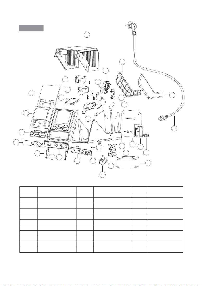
Exploded view of the equipment
22
21
24
1
2
3
4
5
Material nameSerial No. Material name Serial No.
1 Display lens
2 Display board PCB
Fan connector
10
Air plate of fan connector
11
25
30
26
27
29
31
23
20
28
19
16
13
15
12
6
7
8
9
11
17
18
14
10
Material nameSerial No.
Rear O ring
12
Double-row EL2*3Y socket
13
Silicone key 3
14
Interface aluminum 4
Press plate 5
Interface panel 6
Panel 7
18
Interface board PCB 8
Self-adhesive foot pad 9
21 Left decorative plate
Transformer
Bottom shell
51
Power board PCB
61
Plug71
Fuse
Power core 19
Right decorative plate20
23
24
25
26
27
28
Rubber air pipe
Brushless fan
Vacuum pump cover
Vacuum pump
Sponge
Vacuum pump holder
Shock pad29
Fan shock pad30
Fan fixing plate31
22 Top shell
24
Page 27

This product is guaranteed for two years from the date
Product warranty card
of purchase. If any quality problem is found within the
guarantee period, we will response for the
maintenance free of charge on presentation of this
card and the receipt. We will repair and return the
repaired equipment to the customer within 2 working
days of the receipt date.
Note: This warranty card must be attached when this
product is returned to the factory for maintenance,
otherwise free maintenance will not be accepted.
Thank you for your cooperation!
25
Product Certification
Product Model: Product No.:
Inspector: Ex-factory date:
Salesperson: Sold Date:
Page 28

SHENZHEN ATTEN TECHNOLOGY CO.,LTD.
● Soldering iron ● Soldering station ● Hot air rework station
● Multi-function maintenance system
● Regulated DC power supply ● Switching DC power supply
● Programmable power supply
All Copyright Reserved
MADE IN CHINA
CBN029720(A)
 Loading...