

Page 1
GT
compatible
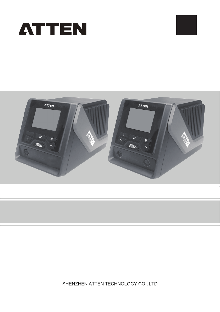
GT-6200/ GT-6150 User Manual
Page 2

Page 3

Contents
Copyright information.........................................................................................2
Description of common icons.............................................................................2
Essential knowledge for users...........................................................................2
Safety precautions.............................................................................................2
Disclaimer..........................................................................................................2
Packing list.........................................................................................................3
Schematic diagram of the whole equipment......................................................5
Connection mode for the whole equipment........................................................5
Connection steps for the whole equipment........................................................6
Technical parameters.........................................................................................7
Description of working interface.........................................................................8
Operations of temperature setup......................................................................10
Quick call the related parameters at certain temperature................................11
Opening and close of GT-6200 channels........................................................12
Parameter setup..............................................................................................13
Total items of parameter setup menu of the host system................................14
Parameter setup menu of the channels for the handle....................................17
Connecting mode of the functional ground wire...............................................21
Maintenance.....................................................................................................22
Product warranty..............................................................................................23
After-sales contact...........................................................................................23
Appendix..........................................................................................................24
Product warranty card......................................................................................25
1
Page 4
Copyright information
The design of this product (including internal software) and its accessories is under the protection of relevant state-laws.Any
violation of the relevant rights of our company will be subject to legal sanctions. Users shall consciously abide by the relevant state
laws when using this product.
Description of common icons
Thank you for using our products. Before using the product, please read this manual carefully and pay attention to the relevant
warnings and cautions mentioned in this manual.
Warning Misuse of this product may lead to serious injury or death to the user.
Caution Misuse of this product may lead to serious injury to the user or material damage to the object involved.
Essential knowledge for users
Users are required to have basic knowledge of common sense and electrical operations before using the product. Minors shall
use the product under the guidance of a professional or guardian.
[Caution]:To avoid damaging the equipment and keep the safety of the operational environment,please read this manual
carefully and keep it well so that you may read it atanytime when necessary.
Safety precautions
To avoid electric shock or injury to the human body or fire hazard,the following basic rules must be observed when using the
equipment.In order to ensure personal safety,only parts and accessories approved or recommended by the original factory
canbe used,otherwise serious consequences may occur!
WARNING
When using this product, the soldering pencil/soldering tip, with the temperature up to 150-480℃, may cause burns to the
user or cause a fire due to improper application.
So Users shall strictly observe the following rules:
●
Keep this product away from flammable materials.
●
Keep the product out of children's reach.
●
Do not use this product if you are inexperienced or have no sufficient necessary knowledge without the guidance of
related personnel.
●
Do not use this product under wet environment or with wet hands to avoid electric shock.
●
Do not modify this product and its accessories without authorization.
●
Please turn off the power when replacing parts and iron tips, and not resume the use until the equipment is completely
cooled down.
●
Please use the accessories from the original factory When replacing the product parts.
●
Make sure to turn off the power switch when the equipment is temporarily stopped or out of use.
WARNING
●
To ensure the normal operation of this product’s ESD function,only three-core power cord shall be used as the host
connectingline.
●
Smoke will be generated during the soldering operations. So please pay attention to the smoke evacuation.
●
Do not play or do other similar dangerous actions during using this equipment, because it can easily lead to injury to
others or yourself.
●
Do not use this product for purposes other than soldering.
●
Do not modify this product and accessories, otherwise the original warranty will be invalidated or damage may occur to
the product.
●
When plugging and unplugging the power cord and handle plug, please hold the plug body and do not pull the cord.
●
Do not hit the product or its accessories too hard during the operation, otherwise damage may occur to the product.
Disclaimer
We will take no responsibility for any personal injury or property damage caused by reasons other than the product quality
problem, which may include force majeure (natural disasters,etc.) or personal behavior during the operation of this product.
This manual is organized, compiled and released by SHENZHEN ATTEN TECHNOLOGY CO.,LTD. according to the latest
product features. We will not responsible for further notice of the subsequent improvement of the product and this Manual.
Page 5
Packing list
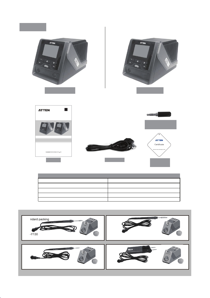
GT-6200 host
GT
compatible
GT-6200/ GT-6150 product manual
Manual
GT-6200 packing list GT-6150 packing list
GT-6200 host
Operation manual
Power cord
Certificate of qualification
3.5mm grounding receptacle 3.5mm grounding receptacle
Standard packing
GT-Y130
(applicable to conventional soldering occasion)
Power cord
GT-6150 host
1
Operation manual
1 1
Power cord
1 1
Certificate of qualification
1 1
1
GT-6150 optional combo
Combo A
GT-Y150
(applicable to lead-free high-power soldering occasion)
GT-6150 host
3.5mm grounding
receptacle
Certificate of
qualification
1
1
Combo B Combo C
GT-Y050 (applicable to precision soldering occasion)
GT-N100 (applicable to precision soldering occasion)
3
Page 6

GT-6200 optional combo
Standard packing
GT-Y130
(applicable to conventional soldering occasion)
Combo A
GT-Y150
(applicable to lead-free high-power soldering occasion)
Combo B
+
GT-N100 (applicable to precision soldering occasion)
+
GT-N100 (applicable to precision soldering occasion)
+
GT-Y050 (applicable to precision soldering occasion)
Combo C
GT-Y050 (applicable to precision soldering occasion)
Combo D
GT-Y050 (applicable to precision soldering occasion)
Combo E
GT-Y130
(applicable to conventional soldering occasion)
Combo F
GT-Y130
(applicable to conventional soldering occasion)
Combo G
GT-Y150
(applicable to lead-free high-power soldering occasion)
GT-N100 (applicable to precision soldering occasion)
+
GT-Y130
(applicable to conventional soldering occasion)
+
GT-Y150
(applicable to lead-free high-power soldering occasion)
+
GT-Y150
(applicable to lead-free high-power soldering occasion)
+
GT-Y130
(applicable to conventional soldering occasion)
+
GT-Y150
(applicable to lead-free high-power soldering occasion)
4
Page 7
Schematic diagram of the whole equipment
4
3
1 2
5 8 967 10 11 121314
USE ONLY WITH 250V FUSE
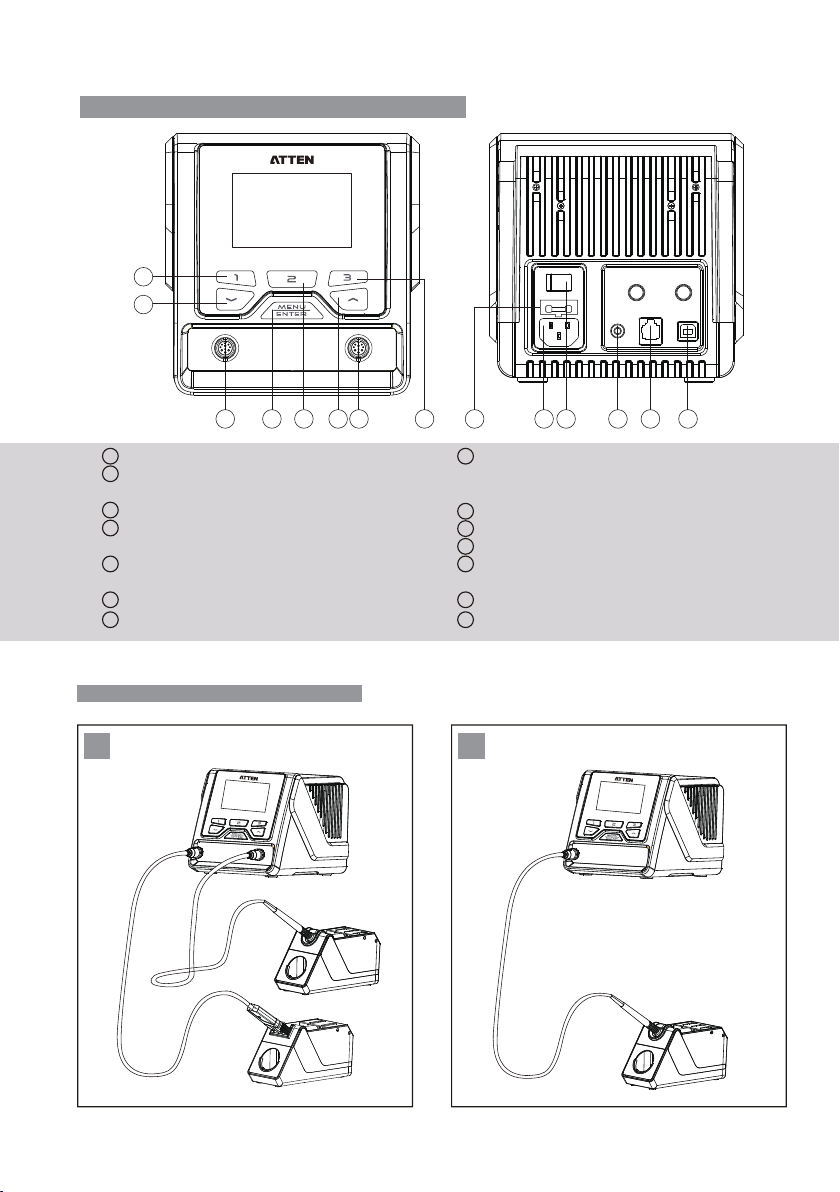
1
Interface for the soldering tool channel 1
2
Interface for the soldering tool channel 2(GT-6150 is not
equipped with such interface)
3
Down arrow key /minus key
4
Rapid temperature key 1, Close key of the Interface for the
soldering tool channel 1,
5
Setup menu switch key of the Interface for the soldering
tool channel 1
6
"Confirm" key, Menu key Up arrow key /minus key
Rapid temperature key 2, System setup menu switch key
7
Connection mode for the whole equipment
1
Connection mode for the whole equipment- GT-6200
8
Rapid temperature key 3, Close key of the Interface for the
soldering tool channel 2, Setup menu switch key of the
Interface for the soldering tool channel 2
Power supply public seat, access rated ac power
9
Power master switch
10
RS232 Communication interface
11
12
USB Communication interface(This function is not
available yet.)
13
Functional grounding interface
Supply fuses
14
2
Connection mode for the whole equipment-GT-6150
5
Page 8
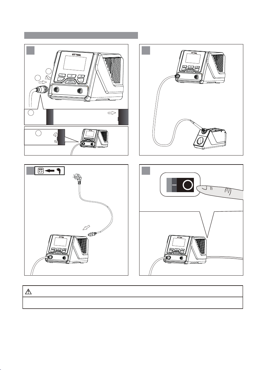
Connection steps for the whole equipment
1 2
2
1
1
2
3 4
Note
To avoid the damage to the host, do not forget to turn off the power when inserting the plug into or removing the plug from
the soldering tools!
6
Page 9
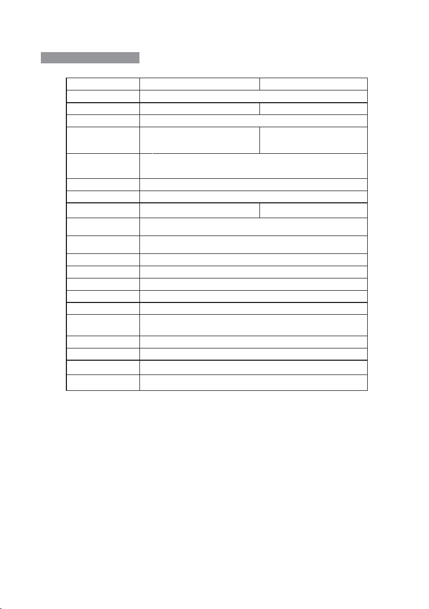
Technical parameters
Product No
Rated working voltage
Rated power 200W 150W
Security Level Class 1(Host of the controller)Class 3(Accessories of soldering handle)
Power fuse
Temperature range
Temperature accuracy
Temperature stability
Number of tool channels
Functional ground
connection
Temperature
adjustment step
Standby mode
Dormancy mode
Rapid temperature
Display resolution
System language
Communication address
range
Working conditions
Storage conditions
Dimension
Weight
Channel 2(can be connected with 2
soldering handles simultaneously)
Long press to adjust 10 units at a time, short press to adjust 1 unit at a time
0~120 minutes, the default time is 0 minutes, turn off Dormancy mode
GT-6200 GT-6150
AC 230V±10% 50Hz(110V±10% 60Hz)
T 2.5A (230V AC)
T 3.15A (110V AC)
150℃ ~ 480℃/ 302℉ ~ 896℉ (Configurable temperature range
depends on the connected accessories of the soldering handle)
±8℃ / ±15 ℉
±2℃ / ±4℉
3.5mm plug(which is hard grounding when not connected, is directly
0~120 minutes, the default time is 0 minutes, turn off Standby mode
connected to the protective ground wire)
3 groups of temperature, which can be called quickly.
240x160 Dots(white letters on blue)
English/Chinese
1~255(not open yet)
Temperature 0℃~40℃Relative humidity<80%
Temperature -20℃~80℃Relative humidity<80%
315(L)×252(W)×127(H)mm
Approximately 4kg
T 2.5A (230V AC)
T 3.15A (110V AC)
Channel 1
7
Page 10
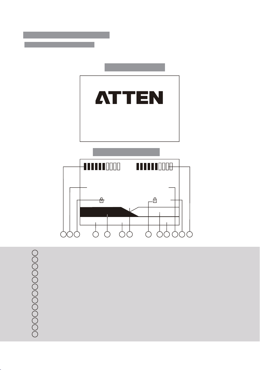
Description of working interface
Description of GT-6200 working interface
After connected with charger.Turn-on the power switch.The product will be working normally after the screen display.System
verion for 3 seconds.
GT-6200 startup interface
6200
GT-6200 normal working interface
189
350 350
Ve rs ion: 1. 0
ww w.atten.com
350
o
c
GT-Y050 GT-Y050
200 300 400
1 13 12 10
Status display area of channel 1, display power bar / product working status / abnormal code.
1
Status display area of channel 2, display power bar / product working status / abnormal code.
2
Actual temperature display area of channel 2, display of the indicative description of abnormal work conditions.
3
Set temperature display area of channel 2.
4
Soldering tool model display area of channel 2.
5
Channel 1/Channel 2 rapid temperature 3.
6
7
Fixed temperature icon display.
System temperature unit display area.
8
9
Channel 1/Channel 2 rapid temperature 2.
Channel 1/Channel 2 rapid temperature 1.
10
Soldering tool model display area of channel 1.
11
Set temperature display area of channel 1
12
13
Actual temperature display area of channel 1, display of the indicative description of abnormal work conditions.
9 8 7 5 6 3 4 2
11
8
Page 11
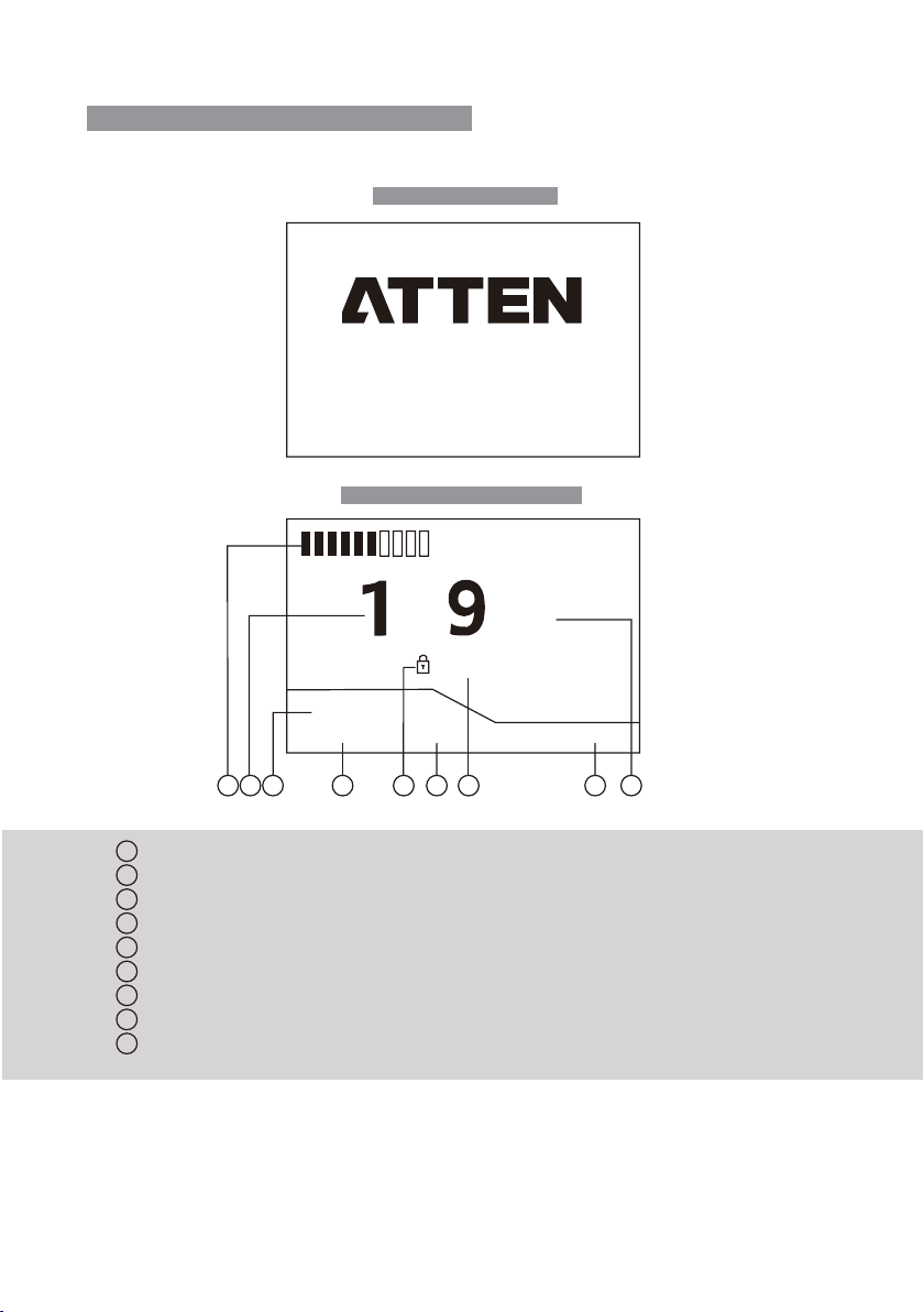
Description of GT-6150 working interface
After connected with charger.Turn-on the power switch.The product will be working normally after the screen display.System
verion for 3 seconds.
GT-6150 start up interface
6150
GT-6150 normal working interface
Ve rs ion: 1. 0
www.atten.com
o
8
c
53 0
GT-Y150
200 300 400
1 9 7 6 3 5
Status display area of channel 1, display power bar / product working status / abnormal code.
1
Channel 1 rapid temperature 3.
2
Fixed temperature icon display.
3
System temperature unit display area.
4
Channel 1 rapid temperature 2.
5
Channel 1 rapid temperature 1.
6
Soldering tool model display area of channel 1.
7
Set temperature display area of channel 1
8
Actual temperature display area of channel 1, display of the indicative description of abnormal work conditions.
9
8
2 4
9
Page 12
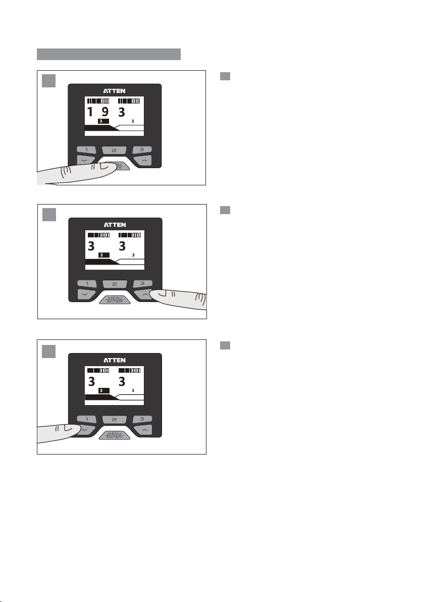
Operations of temperature setup
1
Short press the “MENU” key to select the
1
channel that needs to be configured.
(GT-6150 is not equipped with such channel.)
8
GT-Y050
200 300 400
2
00
GT-Y050
200 300 400
3
0
GT-Y050
200 300 400
5
0
o
50
50
5
50
50
c
GT-Y050
2
Press “UP” arrow key to increase the
temperature.
5
0
o
50
c
GT-Y050
3
Press “DOWN” arrow key to decrease the
temperature.
5
0
o
50
c
GT-Y050
10
Page 13
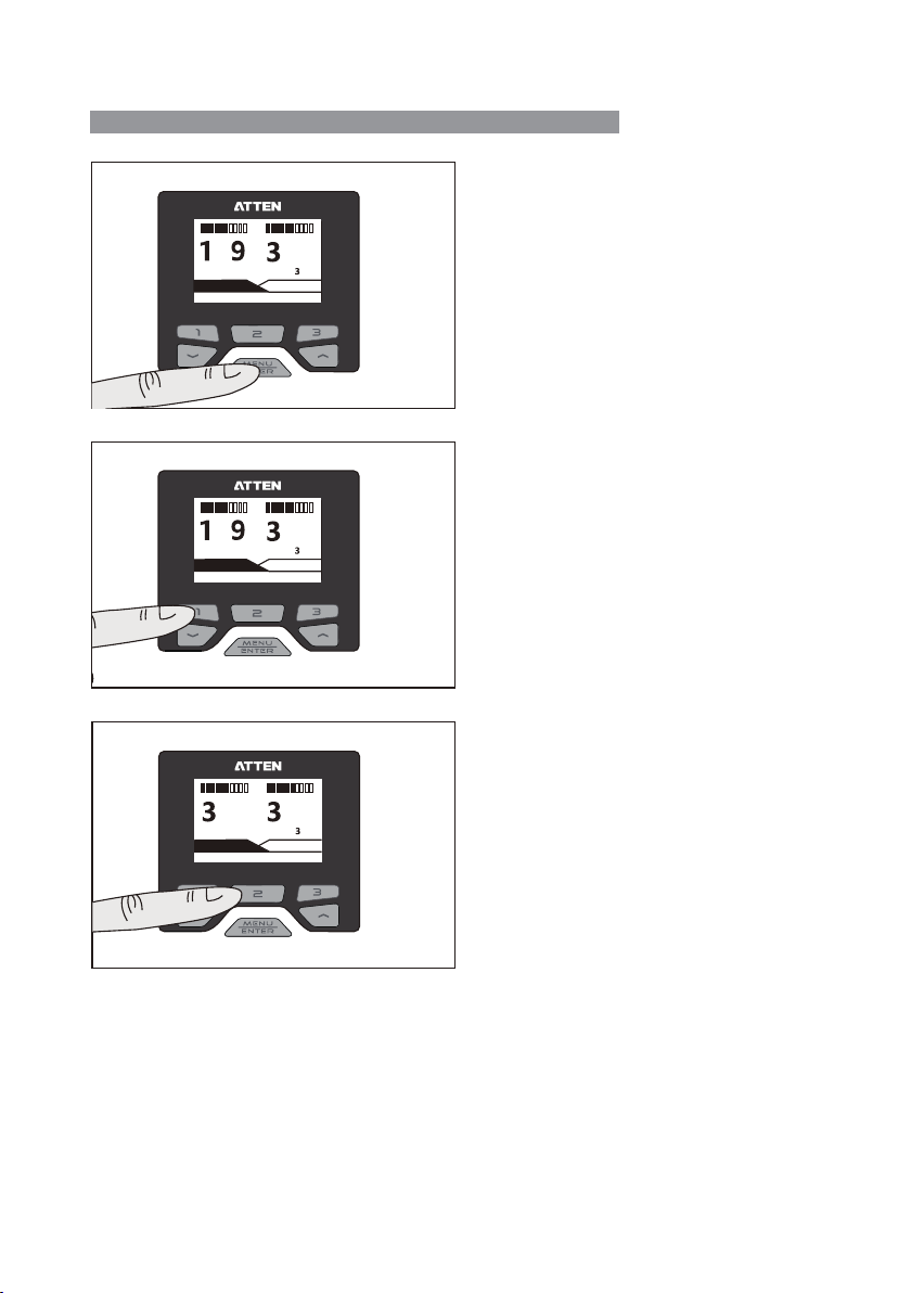
Quick call the related parameters at certain temperature
Short press the “MENU” key to select the tool channel 1 or
tool channel 2.(not available for GT-6150.)
8
GT-Y050
200 300 400
8
GT-Y050
200 300 400
GT-Y050
200 300 400
o
200 50
c
GT-Y050
o
200 50
c
GT-Y050
0
5
o
300 50
c
GT-Y050
5
5
5
0
Short press the "1" key to quickly call the set value at 200℃.
Note:Rapid temperature value can be changed and configured
in the channel menu.
0
Short press the "2" key to quickly call the set value at 300℃.
Likely,short press the "3" key to quickly call the set value at
400℃.
0
11
Page 14
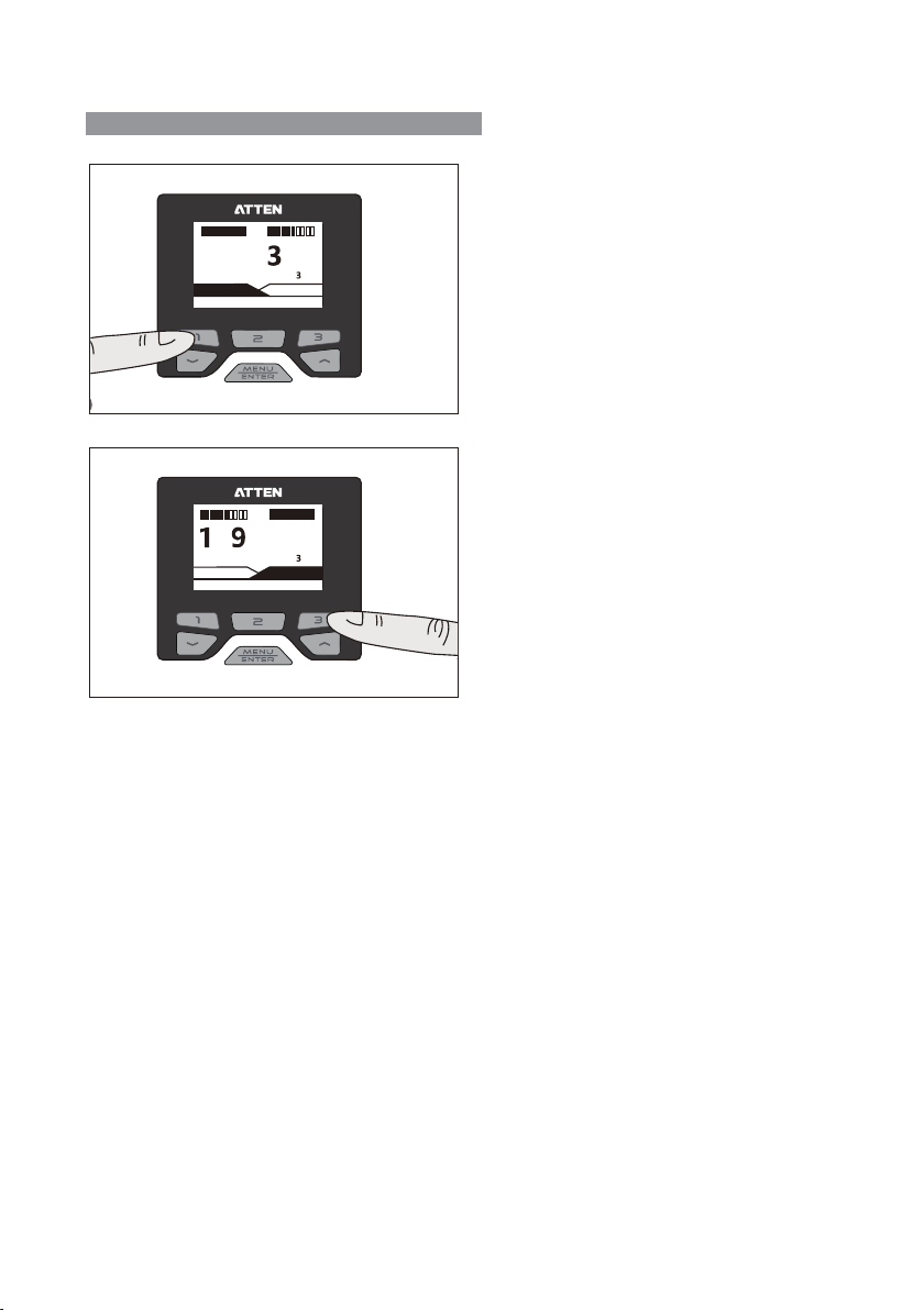
Opening and close of GT-6200 channels
OFF
---
GT-Y050
200 300 400
8
GT-Y050
200 300 400
5
o
200 50
c
GT-Y050
OFF
---
o
200 50
c
GT-Y050
0
Long press "1" key to open or close channel 1.
Long press "3" key to open or close channel 2.
12
Page 15
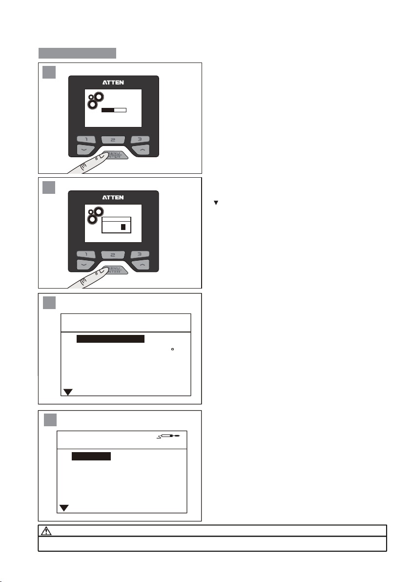
Parameter setup
50%50%
1
Hold "MENU" key until the load is completed (100%).
Load ing.. .
2
Logi n
* *
3
System set
Languages
Unit
Password
Keypad tone
LCD Contrast
4
Channel1 Set
Temp Offset
Standby temp 150
Standby Delay OFF
Shutdown Delay
Shortcut Temp1
If the configuration page is under the protection of password,
the login to “Confirm” page shall be authorized. Press "▲" or
" " key to change the input value, press “Enter" key to
complete one input,press the Rapid temperature key"3",
9
EXIT
En
Press the “Logout” key to return to the main interface.
If there is no password protection, or after the correct
password is entered, it will jump to the System Parameter
setup interface.At this time,the system parameters can be
configured.
C
* * *
ON
4 4
Enter the channel settings page, where the correct handle
corresponding to the channel shall be connect.
GT-Y 050
0
In the System setup screen,use the '1' key and the '3' key to
select the channel to enter.
Note: '1' key corresponds to channel 1, Button '3' corresponds
to channel 2.
(GT-6150 products can only select channel 1.)
OFF
200
Note:
Do not change or insert the handle of the welding tool while setting the channel parameters to avoid damaging the welding
accessories and the Host.
13
Page 16
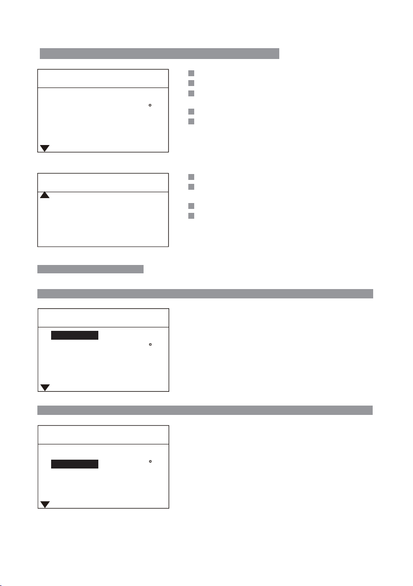
Total items of parameter setup menu of the host system
System Set
Languages
Unit
Password
Keypad Tone
LCD Contrast
System setup
Mode
Net Address 1
Factory Default
En
C
* * *
ON
44
Nor
ON
Languages: Language displayed on the system menu.
Unit: Temperature unit displayed on the system.
Password: The authorization password to enter the system
parameters interface.
Keypad Tone: The switch to turn on and off the key operate tone.
LCD Contrast: Contrast ratio adjustment displayed on the screen.
Mode: Used to define the Host communication.
Net Address: Local communication address defined during
networking operation.
Factory Default: Resume the Host to the factory settings.
Exit: Press to return to the main interface.
Exit
Host system setup parameters
Languages System Set 〉Languages
System Set
Languages
Unit
Password
Keypad Tone
LCD Contrast
En
C
* * *
ON
44
Used to set the system Language:
EN: English.
CN: Chinese. The factory fault is:English.
Unit
System Set
Languages
Unit
Password
Keypad Tone
LCD Contrast
En
C
* * *
ON
44
System Set 〉Unit
Used to set the system temperature unit:
℃: Celsius.
℉: Fahrenheit. The factory default is:℃.
14
Page 17
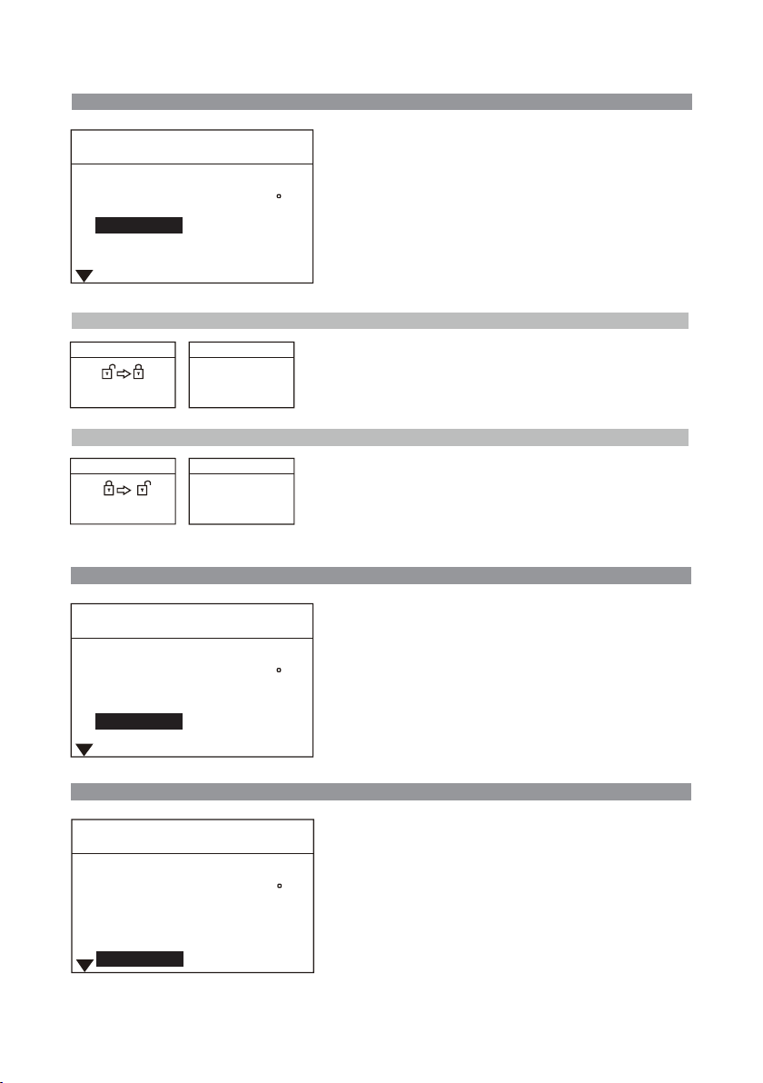
Password System Set 〉Password
System Set
Languages
Unit
Password
Keypad Tone
LCD Contrast
System Lock-in
Set PIN code
0 - -
Locked
PIN Code :
En
C
* * *
ON
44
000
1. Used to lock the system so as to protect the system
settings parameters from being changed by any
unauthorized personnel.
2. Work with the fixed temperature under the
Parameter setup of the channels for the handle to
carry out lockup operation on the whole equipment for
welding processcontrol.
The factory default mode: OFF.
System Set 〉SystemLock-in
When the system is under the password setting state, enter
the three new Password, close the prompt window 3S after
the system displays the “Locked” prompt. Press the "Enter”
key to return to the Password setting item.
System unlock System Set 〉System unlock
Set PIN code
0 - -
Message
PIN code Error
With correct password, the system will be unlocked and
the password will be cleared;
With wrong password, the system will send “wrong password"
prompt;
Keypad Tone System Set 〉 Keypad Tone
System Set
Languages
Unit
Password
Keypad Tone
LCD Contrast
En
C
* * *
ON
44
Used to turn on and off the key operation tone:
ON: There is a prompt tone when the button is pressed.
OFF: There is no prompt tone when the button is pressed.
The factory default is: ON.
LCD Contrast System Set 〉 LCD Contrast
System Set
Languages
Unit
Password
Keypad Tone
LCD Contrast
En
C
* * *
ON
44
Used to set the contrast ratio of the display:
10: The minimum contrast ratio.
100: The maximum contrast ratio.
The factory default is: 44.
15
Page 18
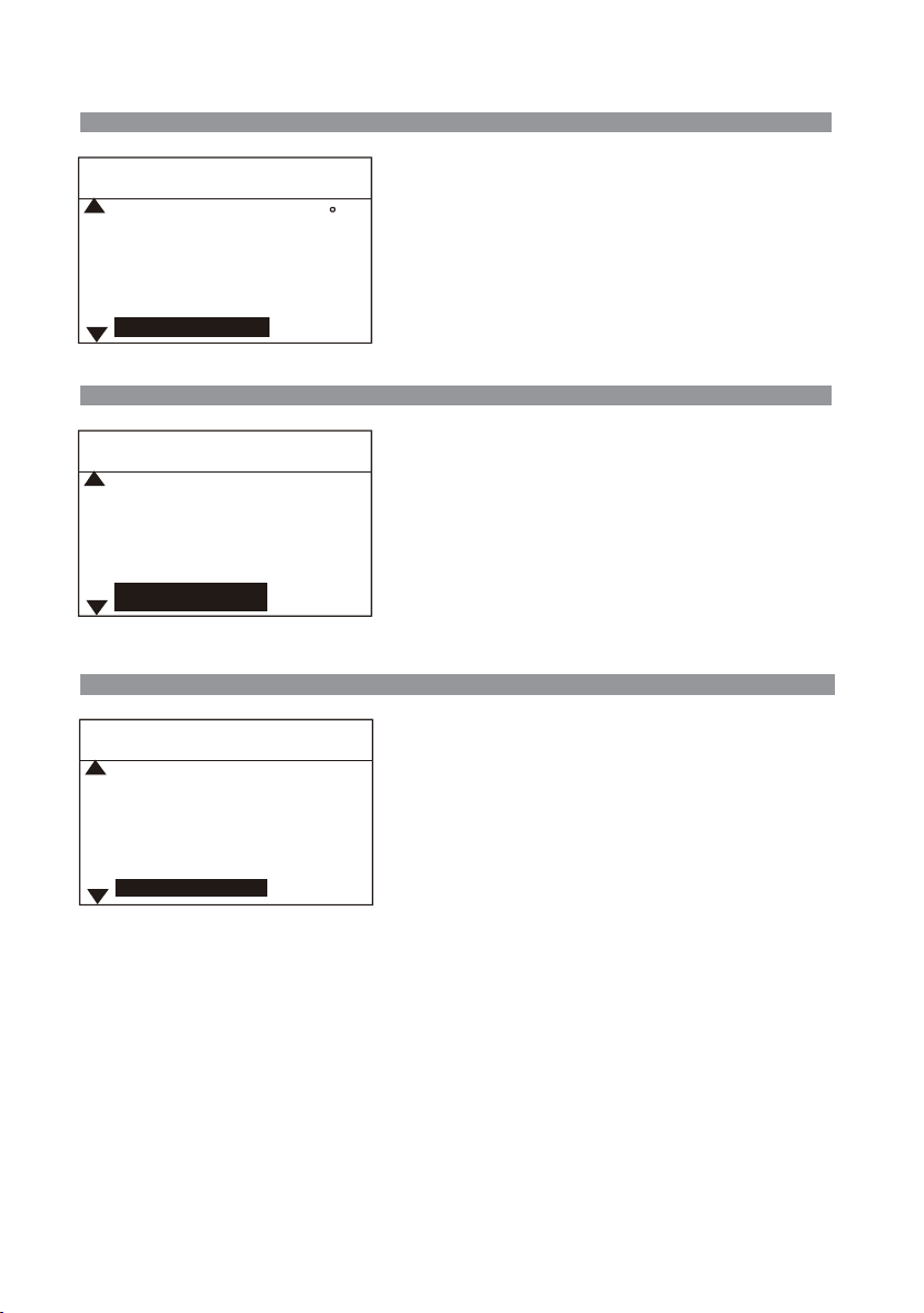
Mode
System Set 〉Mode
System Set
Unit
Password
Keypad Tone
LCD Contrast
Mode
Net Address
System Set
Password
Keypad Tone
LCD Contrast
Mode
Net Address
Factory Default
System Set
Keypad Tone
LCD Contrast
Mode
Net Address
Factory Default
C
* * *
ON
44
Nor
* * *
ON
44
Nor
1
ON
44
Nor
1
Used to set the product's communication mode:
Normal: Turn off the communication function.
Host / Slave: Used for function expansion.
The factory default is: Normal.(this function is
not open yet)
System Set 〉Net Address
Used for the communication between multiple equipment, connecting
up to 255 equipment.
Adjustment range: 1 ~ 255 (used for function expansion).
The factory default: 1.(this function is not open yet)
System Set 〉Factory Default
Used to resume the system setup parameters and channel parameters
to factory default settings.
After clicking the “State as delivered” key, all the system setup
parameters and channel parameters will be resumed to the factory
default settings.
Note: This is only applied to those parameters corresponding to the
model of the connected handle. If the handle is not connected with the
host,the State as delivered function will be not available.
16
Page 19
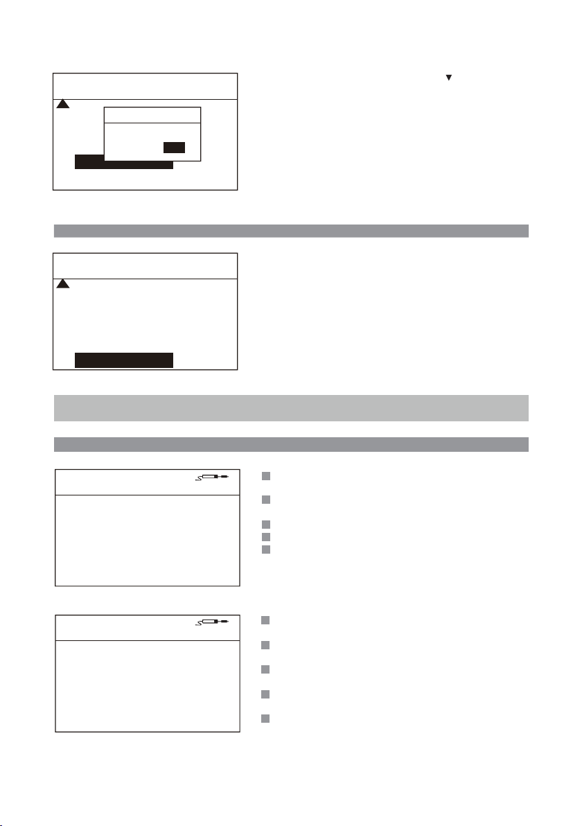
System Set
LCD Contrast
Mode
Net Address
Factory Default
Exit
Factory default?
NO YES
Reset
Reset and operate this dialog box: press “▲” or “ ”to choose
the function and press “Enter” key to perform the function.
44
Nor
1
ON
Exit
System Set
LCD Contrast
Mode
Net Address
44
Nor
1
Click the "Logout" key to return to the main interface.
All changed parameters will be stored after clicking the "Logout" key
and the equipment will then work according to the changed
parameters.
System Set 〉Exit
Factory Default
Exit
Under the system setup menu: press”1” to set the parameter of channel 1; press”2” to set the
parameter of channel 3
Total items of parameter setup menu of the channels for the handle
Channel1 Set
Temp Offset
Standby Temp
GT-Y050
0
150
Standby Delay OFF
Shutdown Delay
OFF
Shortcut Temp1 200
Channel1 Set
GT-Y050
Shortcut Temp2 300
Shortcut Temp3
Fix Temp
400
OFF
Temp UL 480
Temp LL
150
Temp Offset: Used to compensate the error of the
temperature output of the handle.
Standby Temp: The temperature of the handle when the
system is under the standby mode.
Standby Delay: Turn on and off the standby function.
Shutdown Delay: Turn on and off the dormancy function.
Shortcut Temp1: Available for users to quickly call the set
temperature 1.
Shortcut Temp2: Available for users to quickly call the set
temperature 2.
Shortcut Temp3: Available for users to quickly call the set
temperature 3.
Fix Temp: After this mode is activated, the output temperature
is locked at this set temperature value.
Temp UL: the highest temperature that the user
can configure in the main working interface
Temp LL: the lowest temperature that the user
can configure in the main working interface
17
Page 20

Parameter setup menu of the channels for the handle
Temp Offset
Channel1 Set
Temp Offset
Standby Temp
GT-Y050
0
150
Standby Delay OFF
Shutdown Delay
OFF
Shortcut Temp1 200
When replacing the heating element or the handle, the temperature if not accurate, can be calibrated by changing the
following parameter.
Operation is as follows:
1. Set the to-be-calibrated temperature of the handle to a suitable temperature, such as 350° C / 662 °F.
2. After the temperature is stabilized, use the thermometer to measure the actual temperature of the soldering tip of
the current handle, for example, the actual temperature is measured as 365 ℃ / 689 ℉.
3. Through the analysis, it is concluded that the actual current temperature is 15 ℃ / 27 ℉higher than the set temperature.
4. Set the temperature compensation value to -15 ℃ / -27 ℉ F to compensate the error of the output temperature.
Used to compensate the errors of welding pencil
temperature output.
Compensation range: -50 ℃ ~ +50 ℃,-90 ℉ to +90 ℉.
When the value is positive, the handle temperature will
increase according to the set value; when the value is
negative, the handle temperature will decrease
according to the set value.
The factory default value is : 0.
Channel1 Set 〉Temp Offset
Standby Temp
Channel1 Set
GT-Y050
Temp Offset
Standby Temp
Standby Delay OFF
Shutdown Delay
Shortcut Temp1 200
Standby Delay
Channel1 Set
GT-Y050
Temp Offset
Standby Temp
Standby Delay OFF
Shutdown Delay
Shortcut Temp1 200
0
150
OFF
0
150
OFF
Channel1 Set 〉Standby Temp
When the handle is under the standby mode, the maintaining
temperature is:
150 ° C / 302 ° F: the lowest standby temperature.
300 ℃ / 572 ℉: the highest standby temperature value.
When the set actual operating temperature is less than the set
standby temperature, the product will enter the standby mode with
the actual operating temperature.
The factory default is: 150.
Channel1 Set 〉Standby Delay
The product automatically enters into the standby state based on the set
delay value (unit: minute) if the handle is idle for a long time:
1 ~ 120: The product's dormancy mode will be activated, and enters into
the dormant state based on the stipulation time.
OFF: The handle will not enter into the dormancy state.
When the set actual operating temperature is less than the set standby
temperature, the product will enter the standby mode with the actual
operating temperature.
The factory default is: OFF.
18
Page 21
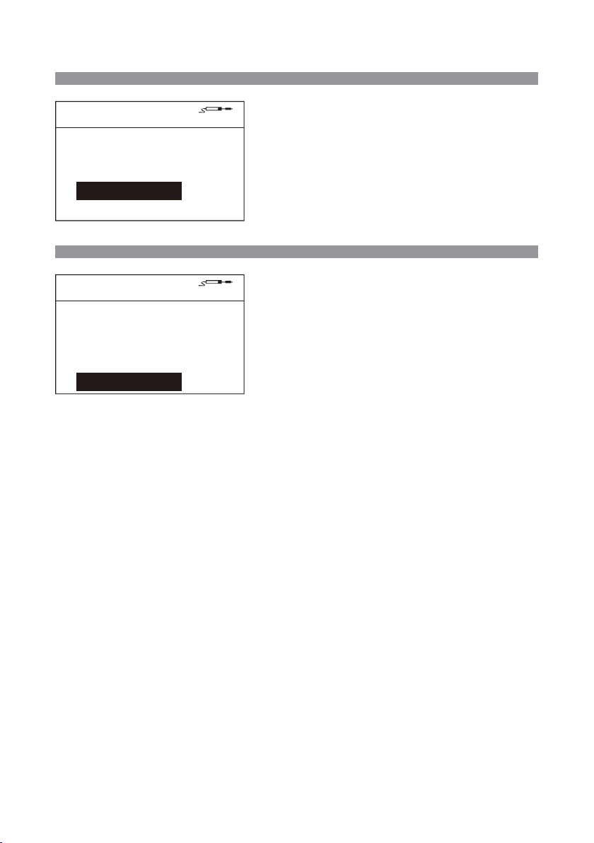
Shutdown Delay
Channel1 Set 〉 Shutdown Delay
Channel1 Set
GT-Y050
Temp Offset
Standby Temp
Standby Delay OFF
Shutdown Delay
Shortcut Temp1 200
Shortcut Temp1
Channel1 Set
GT-Y050
Temp Offset
Standby Temp
Standby Delay OFF
Shutdown Delay
Shortcut Temp1 200
0
150
OFF
0
150
OFF
The product automatically enters into the dormancy state from the
standby state based on the set delay value (unit: minute):
OFF: the product will not enter into the standby state.
1 ~ 120: The product's dormancy mode will be activated, and enters
into the dormant state based on the stipulation time.
Note: The handle will not enter into the dormancy state if the
standby mode is not activated. The factory default is:OFF.
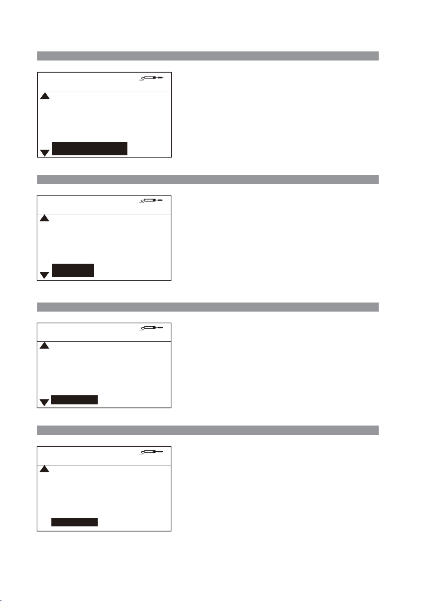
Channel1 Set 〉 Shortcut Temp1
A total of 3 sets of temperature data are available for users to quickly
call subject to the “Temperature lower limit “and “Temperature upper
limit”.
The factory default value is:
Rapid temperature value 1:200℃/392℉.
Rapid temperature value 2:300℃/572℉.
Rapid temperature value 3:400℃/752℉.
19
Page 22
Fix Temp
Channel1 Set 〉 Fix Temp
Channel1 Set
Shutdown Delay
Shortcut Temp1
Shortcut Temp2
Shortcut Temp3
Fix Temp
Temp UL
Channel1 Set
Shortcut Temp1
Shortcut Temp2
Shortcut Temp3
Fix Temp
Temp UL
Temp LL
Channel1 Set
Shortcut Temp2
Shortcut Temp3
Fix Temp
Temp UL
Temp LL
GT-Y050
GT-Y050
OFF
200
300
400
OFF
GT-Y050
200
300
400
OFF
450
300
400
OFF
450
150
When this mode is on, the handle temperature is locked at this set
temperature value.
When the mode is off: temperature lock function is off.
150 ~ 480 ℃ / 392 ~ 896 ℉: The temperature lock function is activated.
The handle is operated according to the fixed temperature value. The
user can not adjust the set temperature value in the main interface.
Factory default: OFF.
Channel1 Set 〉Temp UL
The maximum temperature the user can adjust in the main working
interface.
The configurable maximum temperature is: 480 ° C / 896° F. The
configurable minimum temperature of the "Temperature upper limit"
shall be more than the "Temperature lower limit" value.
The factory default value is: 450 ℃ / 842 ℉.
Channel1 Set 〉Temp LL
The minimum temperature the user can adjust in the main working
interface.
The configurable minimum temperature is: 150 ° C / 302° F. The
configurable maximum temperature of the "Temperature lower limit"
shall be less than the "Temperature upper limit" value.
The factory default value is: 150° C / 302° F.
Exit
Channel1 Set
Shortcut Temp3
Fix Temp
Temp UL
Temp LL
Exit
GT-Y050
400
OFF
450
150
Channel1 Set 〉 Exit
Click the "Logout" key to return to the main interface.
All changed parameters will be stored after clicking the "Logout" key
and the equipment will then work according to the changed parameters.
20
Page 23
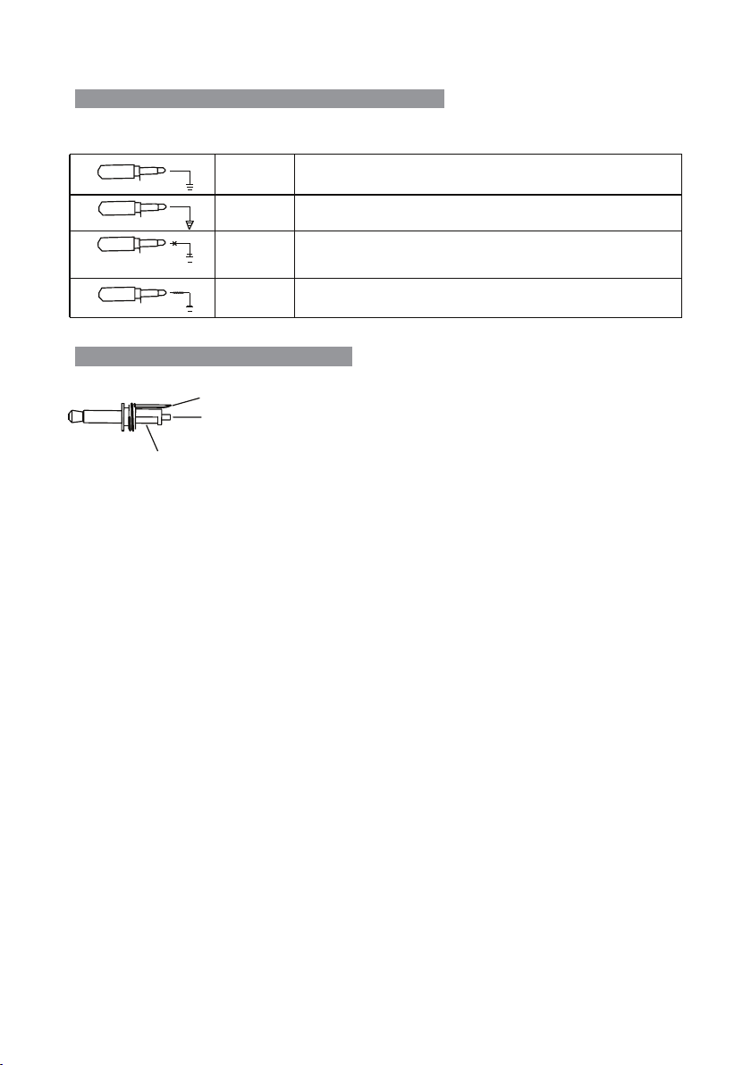
Connecting mode of the functional ground wire
This product uses 3.5mm grounding plug, which is provided with the following four kinds of grounding modes:
1
2
3
4
1MΩ/15 0K
hard ground
equipotential
bonding
Floating
connection
Soft ground
Before the 3.5mm plug is inserted, the ground wire of the soldering tool
handle is connected directly to the protective ground wire of the power line.
After the 3.5mm plug is inserted, the ground wire of the soldering tool
handle is connected to the 3 pins of the 3.5mm plug.
When the 3.5mm plug is direct connected to the socket instead of being
connected to the lead wire, the soldering tool handle is under floating state
and unconnected with any ground.
When the 3.5mm plug is connected to the ground via 1MΩor 150KΩ
resistor,electrostatic discharge loop is formed.
Schematic diagram of thesoldering
3
When the equipotential bonding mode is chosen: the ground wire can achieve the related
2
function via being connected to the pin 1, 2, 3.
1
21
Page 24
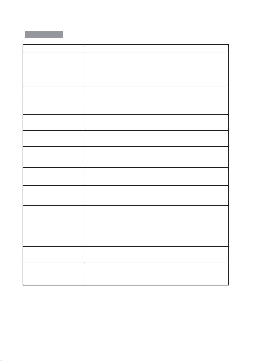
Maintenance
Fault code or fault description
E-1:thermal fuse fault
E-2:sensor alarm
E-3:zero-cross detection
abnormal alarm
E-4:abnormal temperature alarm
E-5:over-current protection
E-6:abnormal system voltage
E-8: abnormal soldering
Tip temperature
E-9: abnormal soldering
handle status
screen display fault:
Likely causes of the faults
1. In case open circuit fault occurs to the heating core, replaceit.
2. In case poor contact occurs to the heating core, unplug and then re-installit.
3. In case the internal connection cable inside the heating core & handle is broken or
heating core connection contact piece is damaged, repair the broken lead wire or
replace the soldering pencil.
4.In case the lead wire inside the 9PIN pencil is disconnected, repair the broken
lead or replace the soldering pencil.
1. In case the heating core is damaged, replaceit.
2. In case open circuit occurs to the lead wire of the Sensor, check the lead wire
of the soldering pencil.
Shall be sent to the designated after-sales service outlet for maintenance.
In case the heating object loses heat too fast, which cannot reach the set specified
temperature even being heated for a long time. You need larger power soldering
equipment.
1. Short circuit occurs inside the heating core.
2. In case short circuit occurs to the internal lead wire of the soldering pencil,please
replace the soldering pencil.
1. In case the external power supply voltage is abnormal, please check if the input
voltage of the product meets therequirements.
2. In case the host of the product is damaged, please send it to the designated aftersales outlet for maintenance.
1. In case the temperature sensor is abnormal, please replace the heatingcore.
2. In case the soldering head temperature is too high, please cool the iron head and
then restart the equipment.
1. In case the handle is not compatible with this equipment, please replace it with the
handle produced by the originalfactory.
2. In case the internal circuit is abnormal, please send the equipment to the
designated after-sales outlet formaintenance.
In case the problem occurs, you can try to adopt the following measures to solve it.
If the problem still cannot be solved, please return the equipment to the original
factory for inspection.
1. Check if the socket switch ison.
2. Check if there is voltage on the socket.
3. Check if the plug with the power line is loose.
4. Check if the fuse is damaged (if so, please replace the fuse according to the
specifications).
inaccurate temperature:
Unreadable code:
1. Use user temperature compensation function to correct the temperature.
2. Replace the heating core with one produced and sent by the original factory.
1. In case there is strong interference source from the outside environment, please
change the application environment or evacuate from the interference area.
2. In case the internal circuit is abnormal, please send the equipment to the
designated after-sales outlet formaintenance.
22
Page 25

Product warranty
●
This product is guaranteed for two years from the date of purchase(excluding consumables such as the heating core). If
any quality problem is found within the guarantee period, we will response for the maintenance free of charge.
●
For those product beyond the warranty period, we provide life-long maintenance services.
●
For those product damaged due to users’ improper application and unauthorized changes to the product parts, our
company only provides limited warranty service.
●
In case of a product fault, please send the faulty product to the designated maintenance shop for maintenance, and those
service center and personnel unauthorized by the factory are prohibited from carrying out any maintenance on the product.
After-sales contact
After-sales service department Tel: (+86) 755-26976387
23
Page 26
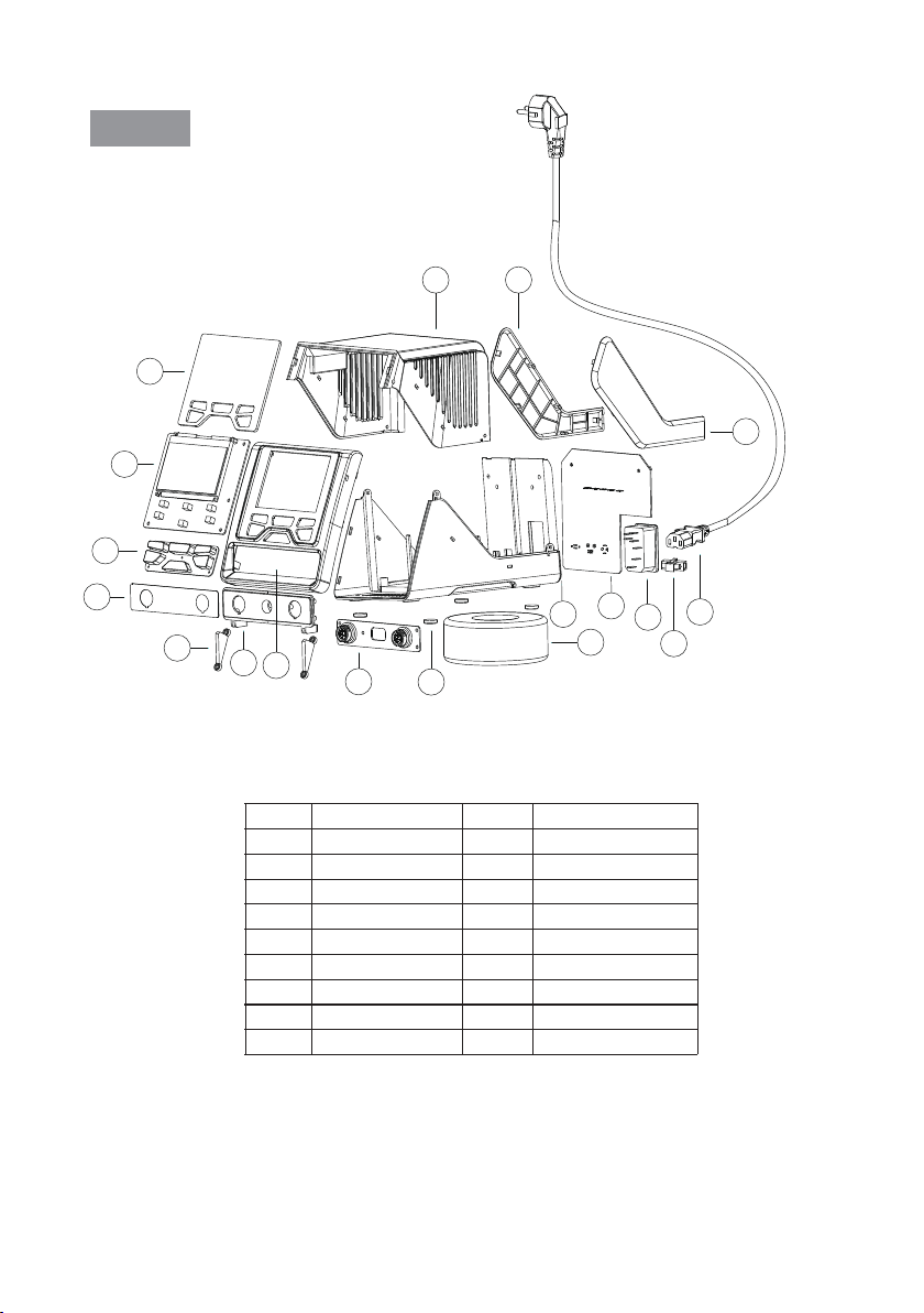
Appendix
Exploded view of the equipment
18
17
1
16
2
3
4
5
6
7
Serial No.
1
2
3
4
5
6
7
8
9
8
Material name
Display Len
Display Board PCB
Silicone key
Interface aluminum
Press plate
Interface panel
Panel
Interface board PCB
Self-adhesive foot pad
9
Serial No.
10
11
12
13
14
15
16
17
18
12
11
13
10
Material name
Transformer
Bottom shell
Power board PCB
Public seat
Fuse
Power cable
Right decorative plate
Left decorative plate
Top shell
15
14
24
Page 27

Product warranty card Product Certification
This product is guaranteed for two years from the date of purchase.
If any quality problem is found within the guarantee
period, we will response for the maintenance free of charge on
presentation of this card and the receipt. We will repair and return
the repaired equipment to the customer within 2 working days of the
receipt date.
Note: This warranty card must be attached when this product is
returned to the factory for maintenance, otherwise free
maintenance will not be accepted. Thank you for your cooperation!
25
Product Model: Product No.:
Inspector: Ex-factory date:
Salesperson: Sold Date:
Page 28
● Soldering iron ● Soldering staon ● Hot air rework staon
● Mul-funcon maintenance system
● Regulated DC power supply ● Switching DC power supply
● Programmable power supply
All Copyright Reserved
MADE IN CHINA
CBN029642(A)
 Loading...