

Page 1
ATTEN.EU
®
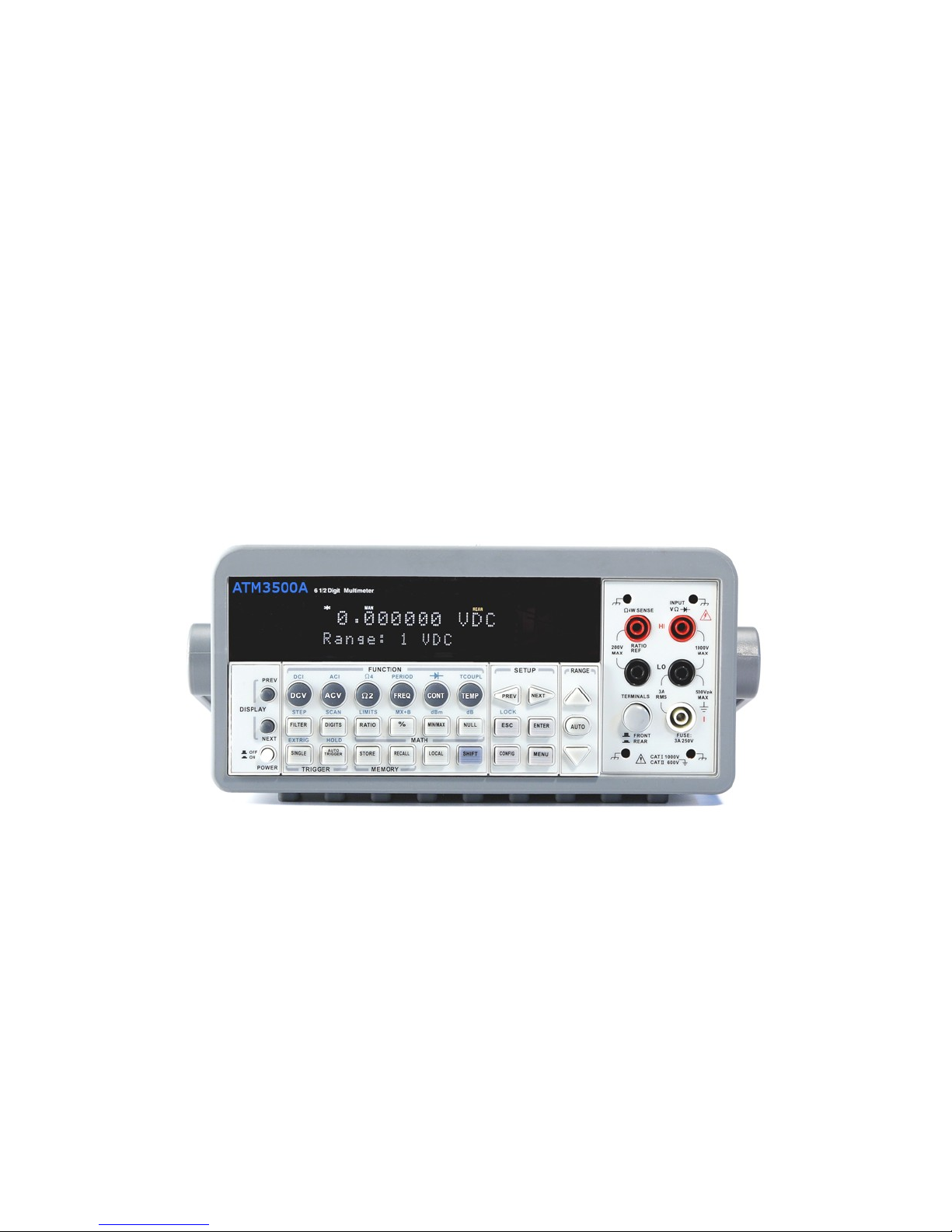
ATM3500A
6.5 Digit Digital Multimeter
Page 2

User’s Manual
ATM3500A DMM
User’s Manual
2
Printed date: 11/2011
Version: 1.05
Page 3

Table of Contents
1
General Information
This section contains general information about ATTEN.EU ATM3500A
Multimeter. The information is shown below:
Feature Overview
Warranty Information
Safety Information
Symbols and Terms
Specifications
Inspection
Options and Accessories
If you have any questions after reading this information, please
contact your local service representative.
1.1 Feature Overview
ATM3500A is a 6.5 digit digital multimeter. It has 0.0015% 24-hour
basic DC voltage accuracy at 10V range and 0.002% 24-hour basic
resistance accuracy at 10kΩ range. At 6.5 digit, the multimeter
delivers 50 triggered RDGS/sec via remote interface. At the fast 4.5
digit, it reads over 2000 RDGS/sec into its internal buffer. ATM3500A
provides wide measurement ranges:
3
Page 4

Note: The 24-hour measurement is subject to calibration accuracy.※
DC voltage: 0.1V, 1V, 10V, 100V & 1000V.
AC voltage: 0.1V, 1V, 10V, 100V & 750V.
DC current: 10mA, 100mA, 1A & 3A.
AC current: 1A & 3A.
2 & 4-wire resistance: 100Ω, 1KΩ, 10KΩ, 100KΩ, 1MΩ, 10MΩ &
100MΩ.
Frequency: From 3Hz to 300kHz.
Period measurement.
Diode measurement.
Continuity measurement for resistance.
Thermocouple temperature & RTD measurements.
Some additional capabilities of ATM3500A include:
Full math functions – dB, dBm, MX+B, ratio, %, Max/Min, null &
limits.
Optional multipoint scanner card – For internal scanning options
including M3500–opt01 (a 10-channel) & M3500-opt09 (a 20-
channel) general-purpose cards.
USB and GPIB/RS-232 (Optional) remote control interfaces.
Through Microsoft Office Word & Excel for remotely storing and
recalling the measured values.
Through M3500 AP software for simulating the real operation on PC.
4
Page 5

1.2 Warranty Information
If the equipment is used in a manner not specified by the
manufacturer, the protection provided by the equipment may be
impaired.
1.
Warranty: ATTEN.EU CORP. guarantees that this product meets
its published specifications at the time of shipment from the factory.
Under proper installation it should work as expected.
2.
Warranty Period: This equipment is warranted against defects in
material and manufacturing for a period of one year from the date
of shipment. During the warranty period, ATTEN.EU is responsible
for necessary repairs as long as the product can be proved to be
defective.
For warranty service or repair this product must be returned to a
service facility designated by ATTEN.EU. Please contact your local
service representative.
3.
Excluded Items: This warranty does not include consumptive
parts such as fuses, buttons and relays. Neither does this warranty
cover defects caused by improper installation, improper or
insufficient maintenance, unauthorized modification, improper
operation, ignorance of environmental specifications or improper
software or interfacing.
4. Remarks:
No other warranty is expressed or implied, except for the above
mentioned.
The remedies provided herein are the buyer’s sole and exclusive
remedies. ATTEN.EU shall not be liable for any direct, indirect,
special, incidental or consequential damages.
5
Page 6

Limitation of warranty
1. Our warranties do not cover any damage resulting from
unauthorized modification or misuse.
2.
Unless mentioned elsewhere in this document, our warranty does
not apply to fuses, probes, and problems arising from normal wear
or your abnormal operations.
3.
Our warranties do not apply on any direct, incidental, special, or
consequential damages.
4.
The above warranties are exclusive and no other warranty is
expressed or implied. ATTEN.EU disclaims any implied warranties of
MERCHANTABILITY, SATISFACTORY QUALITY, and FITNESS for any
particular reasons.
1.3 Precaution of Operation
Please carefully read the manual before operating this device.
This manual is for reference only. Please consult your local service
representative for further assistance.
The contents of this manual may be amended by the manufacturer
without notice.
Never dismantle the equipment by any unauthorized personnel, or
equipment may be damaged.
The equipment has been strictly tested for quality before delivery
from our factory. However, this equipment must not be used in
dangerous situations where damage may result.
This product should be placed in a safe area in case of
6
Page 7

unpredictable personnel use.
The rear protective conduct terminal needs to be connected to the
actual earth ground or electric shock may occur.
The patent and related documents for the equipment belong to
ATTEN.EU CORP. and they aren’t allowed to be used by others
without permission.
1.4 Upkeep of ATM3500A
Although ATM3500A multimeter is very durable and weather
resistant, care should be taken not to expose it to severe impact or
pressure.
Keep ATM3500A far from water and damp environment.
Calibration will be taken every year. Please contact with your local
service representative for more information.
If the incorrect display or abnormal beeps occurred you should stop
using the equipment at once.
Do not use the Meter around explosive gas or inflammable vapor.
Wipe the surface of ATM3500A multimeter with a piece of dry and
clean cloth.
1.5 Safety Information
Caution! Please read through the following safety information
before using the product.
To avoid possible electric shock or personal injury, please read and
follow these guidelines carefully:
Follow the guidelines in this manual and DO NOT use the Meter if
the case is damaged. Check the Meter case and terminals, and
7
Page 8
make sure all the devices are in the proper positions.
Do not apply excessive voltage to the Multimeter. Apply voltage
within the rated range only.
Use caution when measuring voltages above 30 V RMS, 42 V peak,
or 60 V DC. These voltages pose an electric shock hazard.
When using the probes, always keep your fingers behind the finger
guards.
Always connect the common test leads (black) before connecting
the live test leads (red), and disconnect the live test leads (red)
before disconnecting the common test leads (black). This will
reduce the chance of an electric shock.
Disconnect circuit power and discharge all high-voltage capacitors
before testing resistance, continuity, diodes or capacitance.
If you need to open the Meter case or replace any parts, read the
instruction in this manual first. You must be a qualified personnel to
perform this action.
When replacing fuses, use only the same type and same rating as
specified.
Do not try to operate the Meter if it is damaged. Disconnect the
power from the equipment and consult the local service
representative. Return the product to ATTEN.EU service department
if necessary.
1.6 Symbols and Terms
This symbol indicates hazards that may cause damages to the
instrument or even result in personal injury.
This symbol indicates high voltage may be present. Use extra
caution before taking any action.
This symbol indicates the frame or chassis terminal presented
need to be connected to the actual earth ground.
8
Page 9
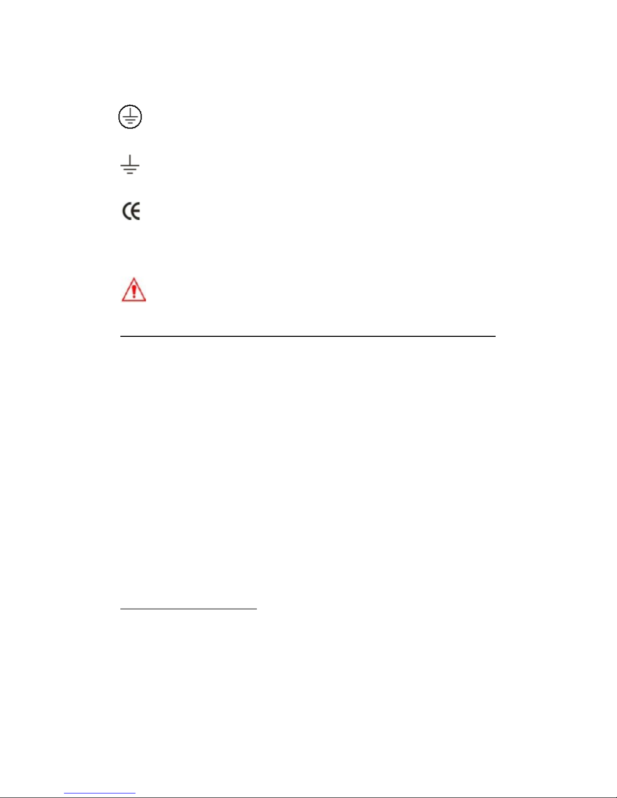
This symbol indicates “Protective Conductor Terminal”.
This symbol indicates earth (ground) terminal.
This symbol indicates this product complies with the essential
requirements or the applicable European laws or directives
with respect to safety, health, environment and consumer
protections.
Note: Full ATM3500A specifications are included in Appendix A.
1.7 Inspection
Your product package is supplied with the following items:
One ATM3500A Multimeter unit. (224mm x 113mm x 373mm,
approx. 4.3 Kg)
One power line cord.
One USB cable.
Standard Test Leads
1
One CD (including this electronic User's Manual and software
applications).
Optional accessories as you ordered. (Refer to the section 1.8
“Accessories”)
1.
The ATM3500A is provided with a Standard Test lead set, described
below.
Test Lead Ratings:
IEC 61010-031 CAT III
9
Page 10
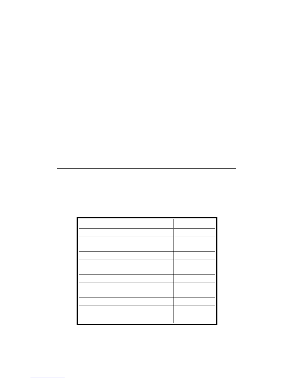
Operating Voltage: 1000V DC
Current: 10 Ampers
UL/CE Rated
Material:
Probe Body: Outer Insulation-Santoprene Rubber.
Banana Plug: Body Brass, Nickel Plated Spring Beryllium Copper, Nickel
Plated.
Insulation: Polypropylene Resin Flasme Retardant Grade 2038.
Others
If any part of the Test Lead Set is damaged, please do not use and replace
with a new set.
Warning: If you use the Test Lead Set which is not qualified by※
ATTEN.EU Corp., the protection of the Test Lead Set could be
impaired. In addition, please don’t use a damaged Test Lead Set
against the instrument break or personal injury.
1.8 Accessories
The following accessories are available from ATTEN.EU for use with the
Model ATM3500A. Please refer to the following Table 1-1.
Table 1-1
Part Name Part Number
10-Channel Multi-point Scanner Card M3500-opt01
Thermocouple adapter M3500-opt02
Adapters (Banana to BNC Adapter) M3500-opt03
GPIB Card M3500-opt04
RTD Probe Adapter M3500-opt05
RS232 Adapter M3500-opt06
Kelvin Probe M3500-opt07
4-Wire Test Leads M3500-opt08
20-Channel Multi-point Scanner Card M3500-opt09
Shorting Plug M3500-opt10
K Type Thermocouple Lead M3500-opt11
10-Channel TC-Scanner Card M3500-opt12
10
Page 11

1.9 ATM3500A’s Dimension
Please get the dimension’s information in the following different ways.
1.
The dimension without the handle and the front & Rear Bumpers is
in the following Picture 1. (LxWxD - 213.6x88.6x370 mm)
2.
The dimension with the handle and the front & Rear Bumpers is in
the following Picture 2. (LxWxD - 255x113x373 mm)
3.
The dimension with the front & Rear Bumpers, but without the
handle is in the following Picture 3. (LxWxD - 224x113x373 mm)
11
1
2
3
Page 12

2
Overview
This chapter will give you an overview of ATM3500A’s basic features
and guide you through the basics of ATM3500A digital multimeter. You
will become familiar with those features after reading this chapter.
2.1 Setting up Your ATM3500A Digital
Multimeter
You may want to check if your multimeter is ready for measurement.
In fact, all of the ATTEN.EU products are inspected perfectly before
being shipped to our customers. If you find any damaged or missing
parts, please contact your local service representative immediately and
do not attempt to operate the damaged product. If having any doubt
of your products, you are encouraged to contact the local service
representative.
2.1.1 To adjust the handle
You may adjust the carrying handle to suit your needs. The following
figures show you how to adjust the handle.
I. Taking off the handle from the Multimeter
【
Step 1】(Turn up the handle)
Pull slightly outward on both sides of the handle and slowly rotate it up
as shown in Figure 1-1.
12
Page 13
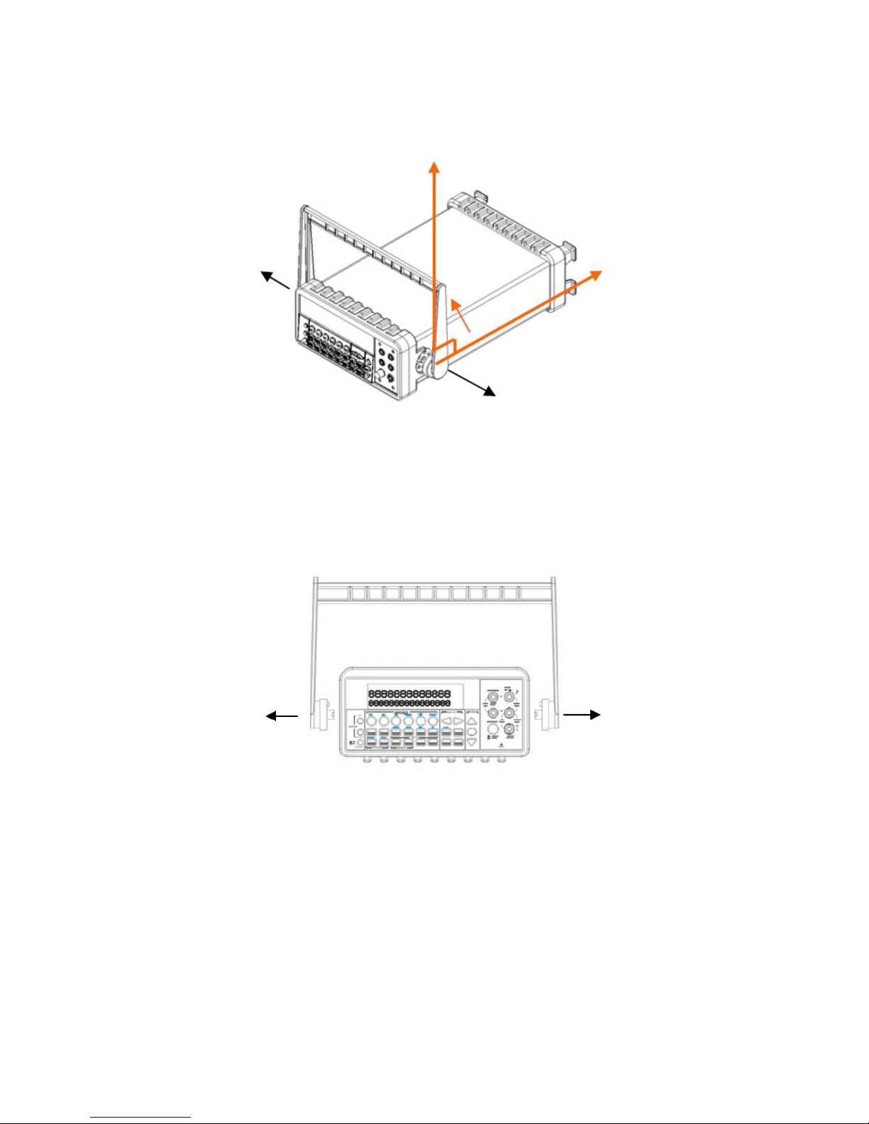
Figure 1-1
【
Step 2】(Pull out the handle)
When the handle is turned up to 90° with the multimeter please pull
out the handle from the multimeter as shown in Figure 1-2.
Figure 1-2
Ⅱ
. Adjusting the position for your convenience
Here are some referable positions for your reference.
【
Position 1
】
The default position is for packing as shown in Figure 1-3
。
13
Page 14
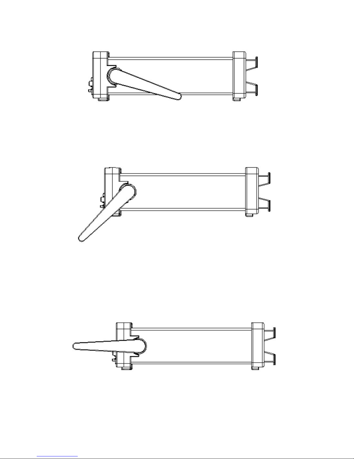
Figure 1-3
【
Position 2
】
The adjusted position is for operation as shown in Figure 1-4
。
Figure 1-4
【
Position 3
】
The carrying position is with the handle as shown in Figure 1-5
。
Figure 1-5
14
Page 15
2.1.2 To connect the power
Check the power-line voltage on the rear panel to see if voltage setting
is correct for your area. Change the setting if it is not correct or the
fuse is broken. Please follow the steps below.
2.1.2.1 To convert the voltage
Warning! In some areas, the power supplied voltage is 240V or
120V; in others, the power supplied voltage is 220 V or 100 V. Please
refer to your local power supplied voltage to see if you have the right
setting.
Warning! Before changing the setting, make sure the multimeter
is disconnected from the AC power. An incorrect voltage setting may
cause severe damage to your instrument.
Warning! The power cord supplied with ATM3500A contains a
separate ground wire for use with grounded outlets. When proper
connections are made, instrument chassis is connected to power line
ground through the ground wire in the power cord. Failure to use a
grounded outlet may result in personal injury or death due to electric
shock.
Suppose your condition is in AC 100V and you want to convert the
voltage to the 220V. Follow these steps to change the voltage setting.
【
Step 1
】
Verify that the meter is disconnected as shown in Figure 2-1.
15
Page 16
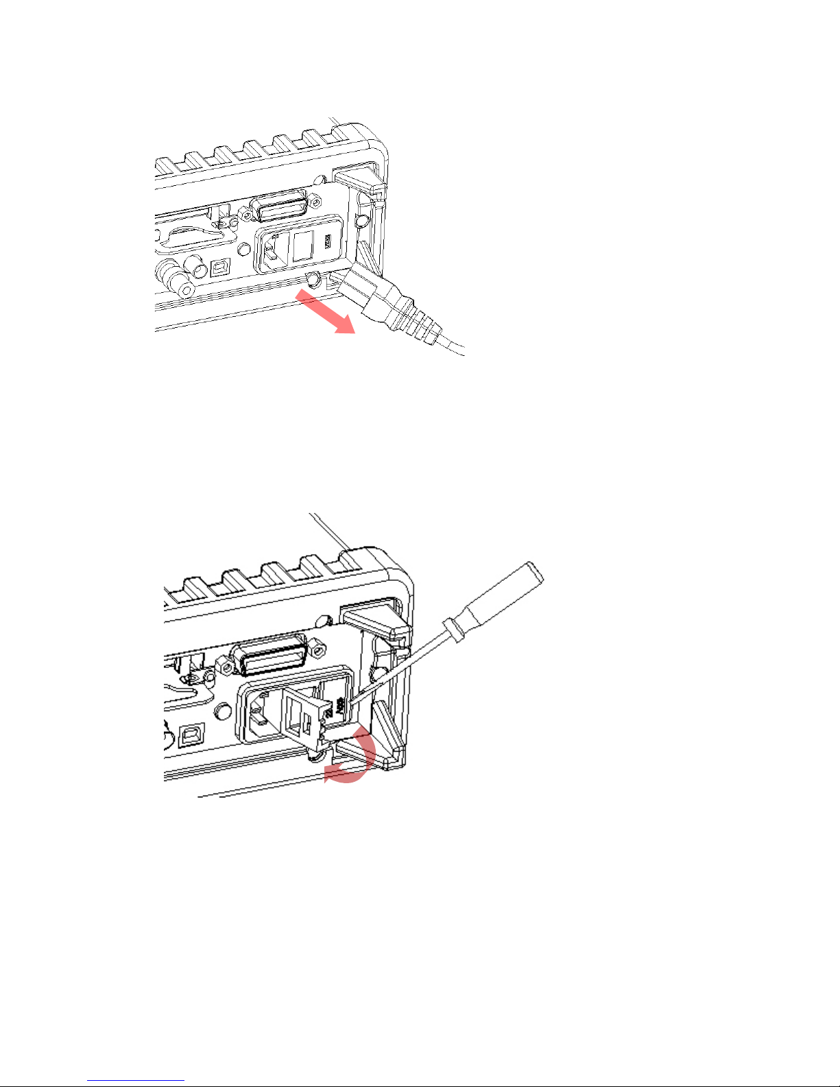
Figure 2-1
【
Step 2
】
Open the voltage setting selector cap as shown in Figure 2-2. (You
might need a screwdriver to do so.)
Figure 2-2
【
Step 3
】
Remove the red voltage setting selector from the right middle seam as
shown in Figure 2-3. (You might need a screwdriver to do so.)
16
Page 17
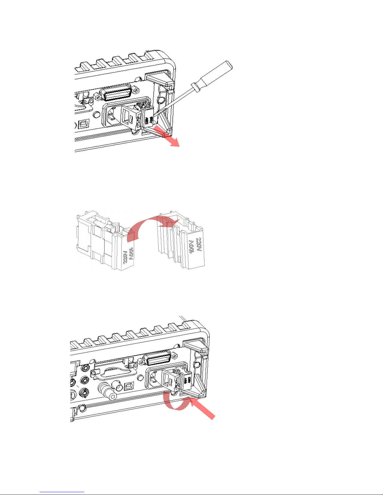
Figure 2-3
【
Step 4
】
Turn it over to 220V position as shown in Figure 2-4.
Figure 2-4
【
Step 5
】
Insert the voltage setting selector back into the socket and close the
cap as shown in Figure 2-5.
Figure 2-5
17
Page 18
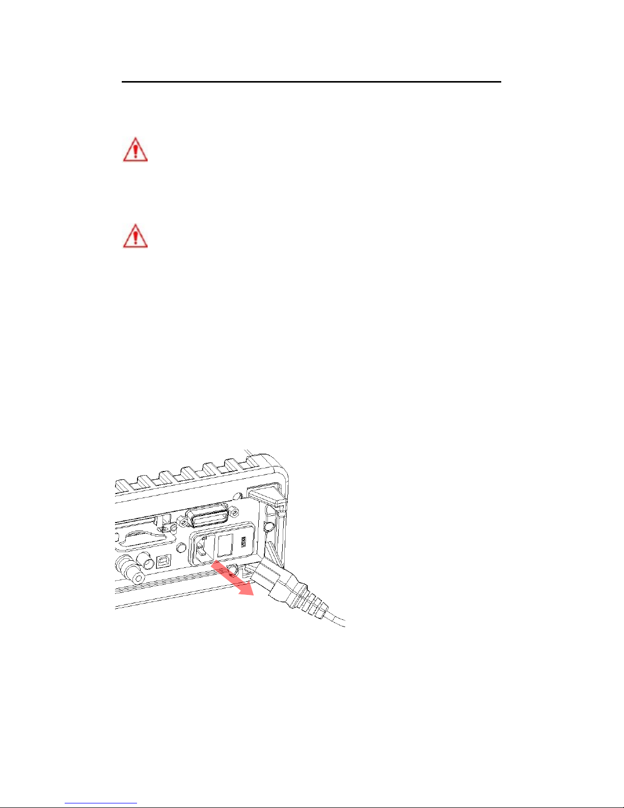
2.1.2.2 To change the fuse
Warning! Before replacing the power-line fuse, make sure the
multimeter is disconnected from the AC power. You must be a qualified
personnel to perform this action.
Warning! For continued protection against fire or instrument
damage, only replace fuse with the same type and rating. If the
instrument repeatedly blows fuses, locate and correct the cause of the
trouble before replacing the fuse.
Verify that the power-line fuse is good. Replace the fuse if it is
damaged. Use only the same type and same rating fuse noted on the
rear panel. Please follow the steps below to change the fuse.
【
Step 1
】
Verify that the meter is disconnected as shown in Figure 2-6.
Figure 2-6
18
Page 19
【
Step 2
】
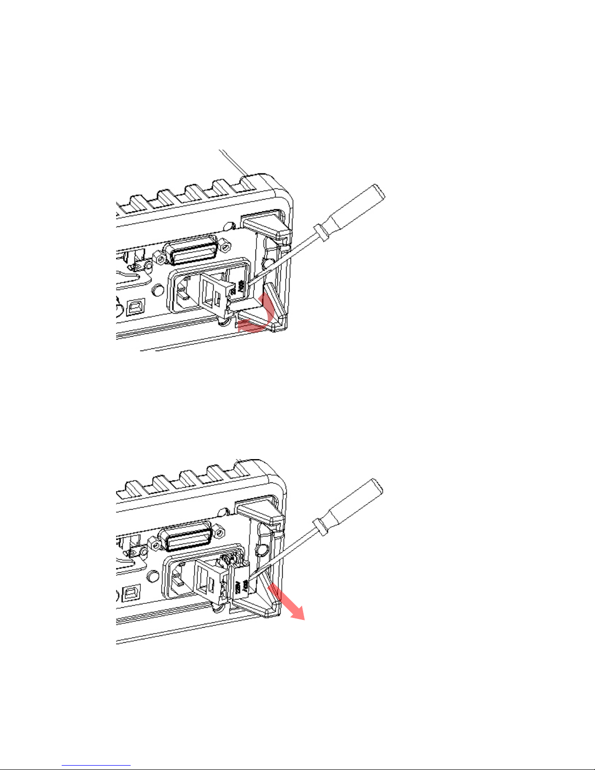
Open the voltage setting selector cap as shown in Figure 2-7. (You
might need a screwdriver to do so.)
Figure 2-7
【
Step 3
】
Remove the red voltage setting selector from the right middle seam as
shown in Figure 2-8. (You might need a screwdriver to do so.)
Figure 2-8
19
Page 20
【
Step 4
】
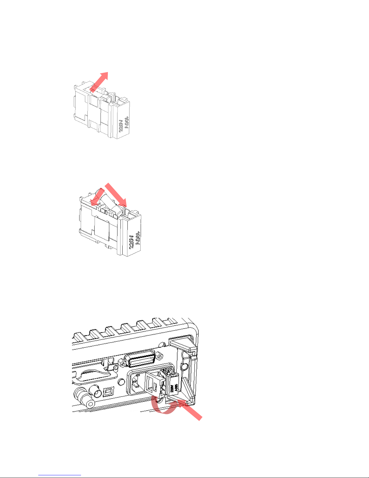
Remove the broken fuse from the selector as shown in Figure 2-9.
Figure 2-9
【
Step 5
】
Replace with the new fuse as shown in Figure 2-10.
Figure 2-10
【
Step 6
】
Insert the voltage setting selector back into the socket and close the
cap as shown in Figure 2-11.
Figure 2-11
20
Page 21
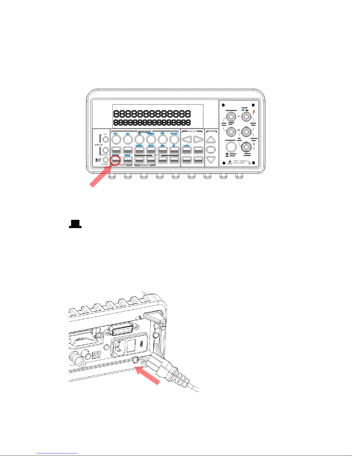
【
Step 7
】
Make sure the power switch on the front panel is in “Power OFF”
condition before plugging as shown in Figure 2-12.
Figure 2-12
Power switch:
“POWER OFF”
【
Step 8
】
After finishing the above procedures, you can plug in your power cord
as shown in Figure 2-13.
Figure 2-13
21
Page 22
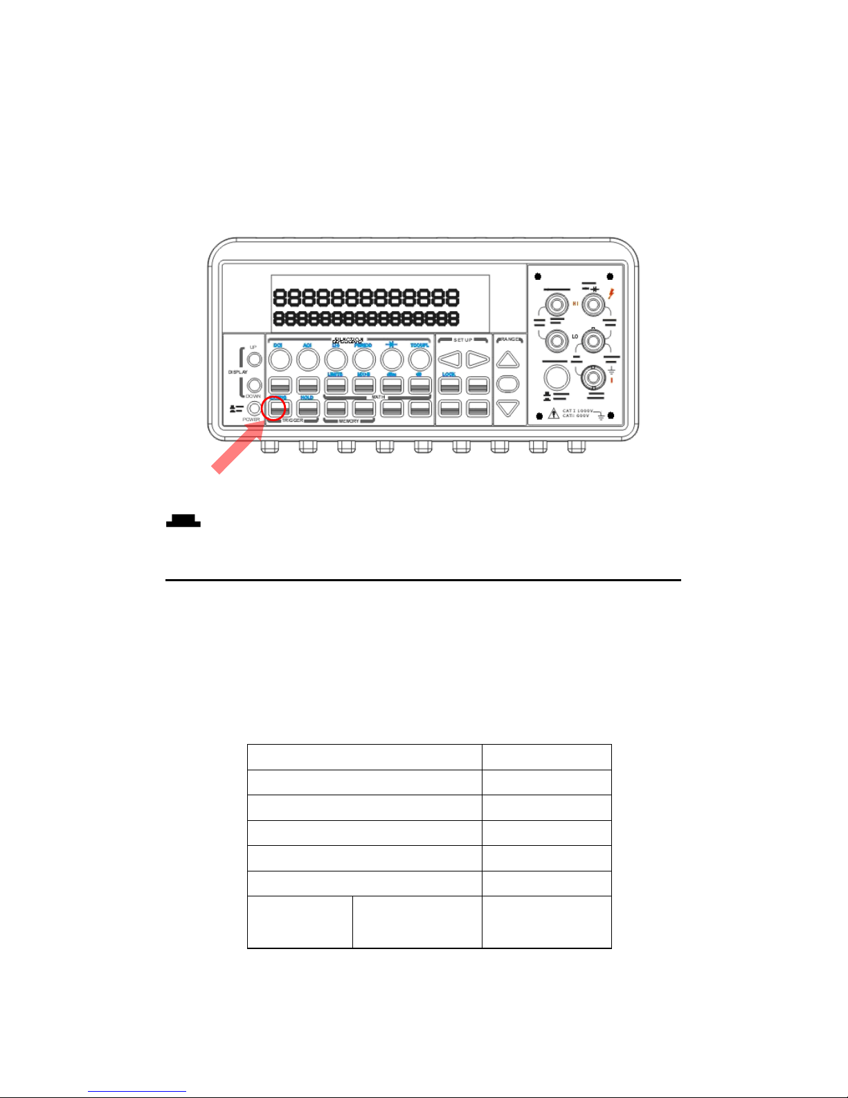
【
Step 9
】
Press on the power switch on the front panel for activating ATM3500A
as shown in Figure 2-14.
Figure 2-14
Power switch:
- “POWER ON”
2.1.3 Factory Default When Power-ON
Table 2-1 shows the factory default of ATM3500A.
Table 2-1
Function Default
Function DCV
Autozero On
Frequency and Period Source AC Voltage
Output Format ASCII
Ratio Off
AC
Bandwidth
Input
Frequency
20Hz
22
Page 23
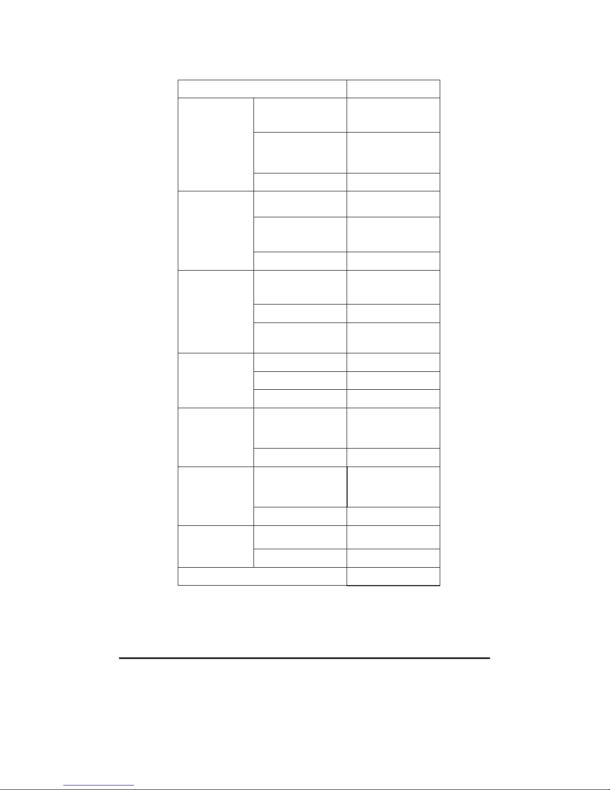
Function Default
Voltage AC Digits 5.5
DC digits Slow 5.5
(1 PLC)
Range Auto
Current AC Digits 5.5
DC Digits Slow 5.5
(1 PLC)
Range Auto
Frequency
and Period
Digits 5.5
Range AUTO
Rate Medium
(100ms)
Diode Test Digits 5.5
Range 1mA
Rate 0.1 PLC
Resistance
(2-wire)
Digits Slow 5.5
(1 PLC)
Range Auto
Temperature Digits Slow 6.5
(10 PLC)
Thermocouple Universal Type
Triggers Source Immediate
Delay Auto
Input Resistance 10MΩ
2.2 Features
23
Page 24
Resolution: 6.5 digits.
5*7 dot matrix VFD, dual displays with 3-color annunciators.
11 standard measurement functions & 8 math functions.
4 front ground terminal are connected to Chassis.
Stability, Accuracy and Speed (2000RDGS/Sec at 4.5 Digit, 60
RDGS/Sec at 6.5 Digit in 60 Hz)
Multi-Points Scanner Card: Up to 20 Channels. (Optional)
RTD probe Adapter (optional) convenient to use.
Built-in USB and GPIB/RS-232 (Optional) Interfaces.
Easy & Free PC applications.
2.3 ATM3500A Function Introduction
To become familiar with the ATM3500A DMM, ATTEN.EU will provide
you the brief introduction of the basic ATM3500A DMM operations.
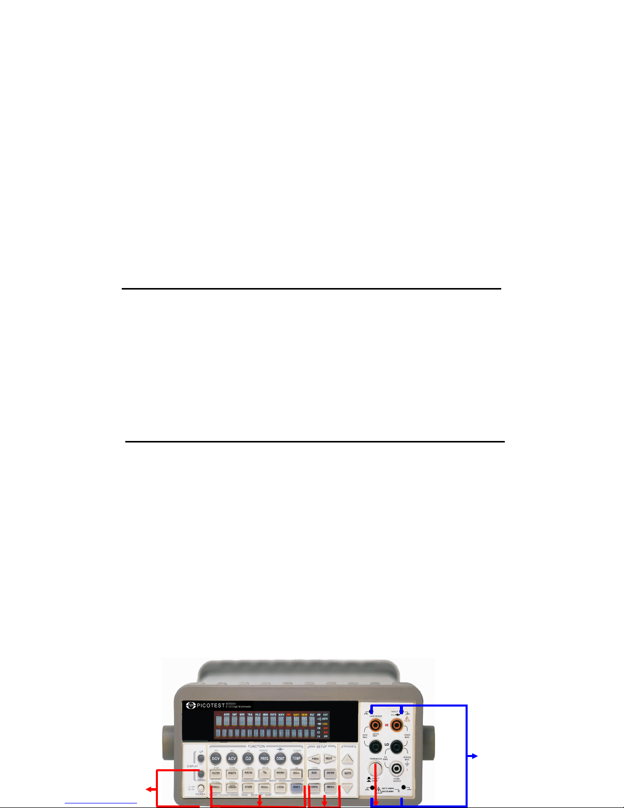
There are three major parts of ATM3500A: (2.3.1) the front panel,
(2.3.2) the display, and (2.3.3) the rear panel.
2.3.1 The Front Panel
There are different buttons and terminals on the front panel. They are
divided into the following groups: (DISPLAY & POWER), (FUNCTION,
MATH, TRIGGER, MEMORY, SETUP, RANGE, INPUT TERMINALS), and
(FILTER, DIGITS, LOCAL, and SHIFT) as shown in Figure 2-15.
24
1
2 3 4 5
Page 25

Figure 2-15
1. Power & Display:
Power: Activates ATM3500A DMM.
Display: Shows model, version & condition by pressing round PREV
& NEXT buttons.
2.1.
First row without SHIFT button:
DCV: Selects DC voltage measurement.
ACV: Selects AC voltage measurement.
Ω2: Selects 2-wire resistance measurement.
FREQ: Selects frequency measurement.
CONT: Selects the continuity test.
TEMP: Selects RTD temperature measurement.
2.2.
First row with SHIFT button:
DCI: Selects DC current measurement.
25
6
7
Page 26
ACI: Selects AC current measurement.
Ω4: Selects 4-wire resistance measurement.
PERIOD: Selects period measurement.
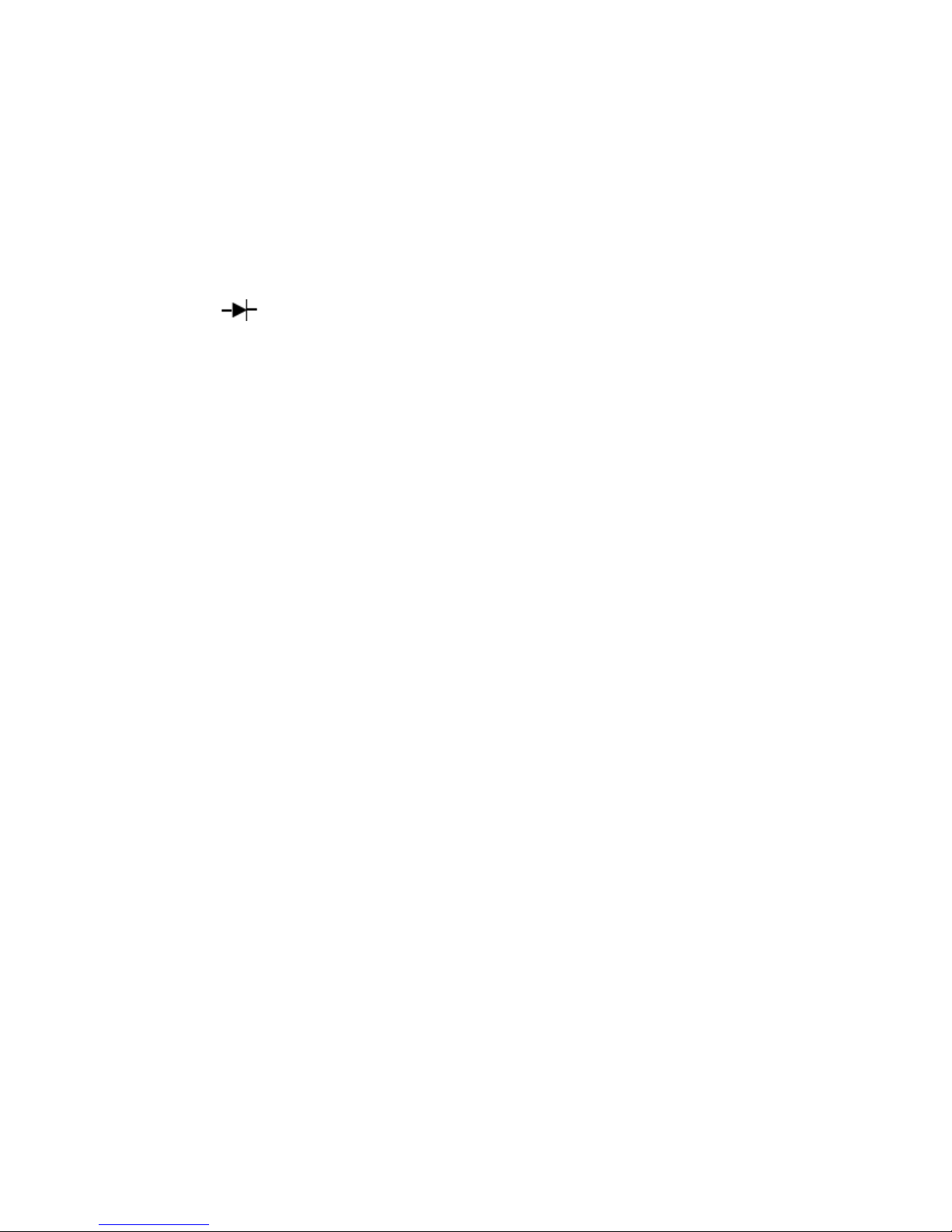
: Selects diode testing.
TCOUPL: Selects thermocouple temperature measurement.
2.3.
Second row without SHIFT button:
FILTER: Enable or disable the digital filter.
DIGITS: Changes resolution.
RATIO: Enables the dcv:dcv ratio function.
%: Calculates the ratio to a target value in percentage.
MIN/MAX: Captures the minimum or maximum readings from the
measurement.
NULL: Activates the offset function in order to get the real
measured reading.
2.4.
Second row with SHIFT button:
STEP: Scans from a channel to the next channel in delayed action
when using the scanner card.
SCAN: Enables scanning function when using the scanner card.
LIMITS: Used for Setting upper and lower limit values for readings.
MX+B: Used for calculating slope. X is the normal display reading.
M and B are constants defined by user for scale factor and offset.
26
Page 27

dBm: Used for displaying voltage measurement in dBm power unit.
dB: Used for displaying voltage measurement in decibel unit.
2.5.
Third row without SHIFT button:
SINGLE: Manually triggers the multimeter to make measurements.
AUTO TRIGGER: Instructs the multimeter to make measurements
continuously.
STORE: Stores a specified number of subsequent readings.
RECALL: Displays stored readings and buffer statistics. Use ◁▷ or
△▽ searching buttons to toggle between reading number and
reading.
LOCAL: Cancels USB or GPIB remote mode.
SHIFT (in blue): Used for accompanying other button with upper
print in blue and converting function.
2.6.
Third row with SHIFT button:
EXTRIG: Selects external triggers as the trigger source via BNC port
on the rear panel.
HOLD: Holds reading.
3.1.
The first row in SETUP section
◁▷: Scrolls through buffer, conceals or reveals the digits while
measuring.
27
Page 28

3.2.
The second row in SETUP section:
ESC: Cancels selection, moving back to measurement display.
ENTER: Accepts selection, moving to next choice or back to
measurement display.
LOCK: Presses SHIFT then ESC button to prevent unpredictable
operation on the panel. In order to release lock condition, please
press ESC again.
3.3.
The third row in SETUP section:
CONFIG: Offers setting or adjusting function, relating some front
panel buttons.
MENU: Offers setting or adjusting function, not relating other front
panel buttons.
4. RANGE:
: Moves to higher range.△
: Moves to lower range.▽
AUTO: Enables or disables auto-range.
5.
Terminals: Selects input signal connections on front or rear
panel.
6. Inserted Connections & Fuse Device:
4 Chassis Ground Connections: Separate environmental noises.
HI & LO: Used for all measurements, except DC and AC current.
(Maximum input voltage: 1000V for voltage measurements. 200V
for 4-wire measurement)
28
Page 29
LO & I: Used for making DC and AC current measurements.
Front Fuse: Secures your Meter against damage of strong current
pulse. (Maximum current: 3A, 250V)
7.
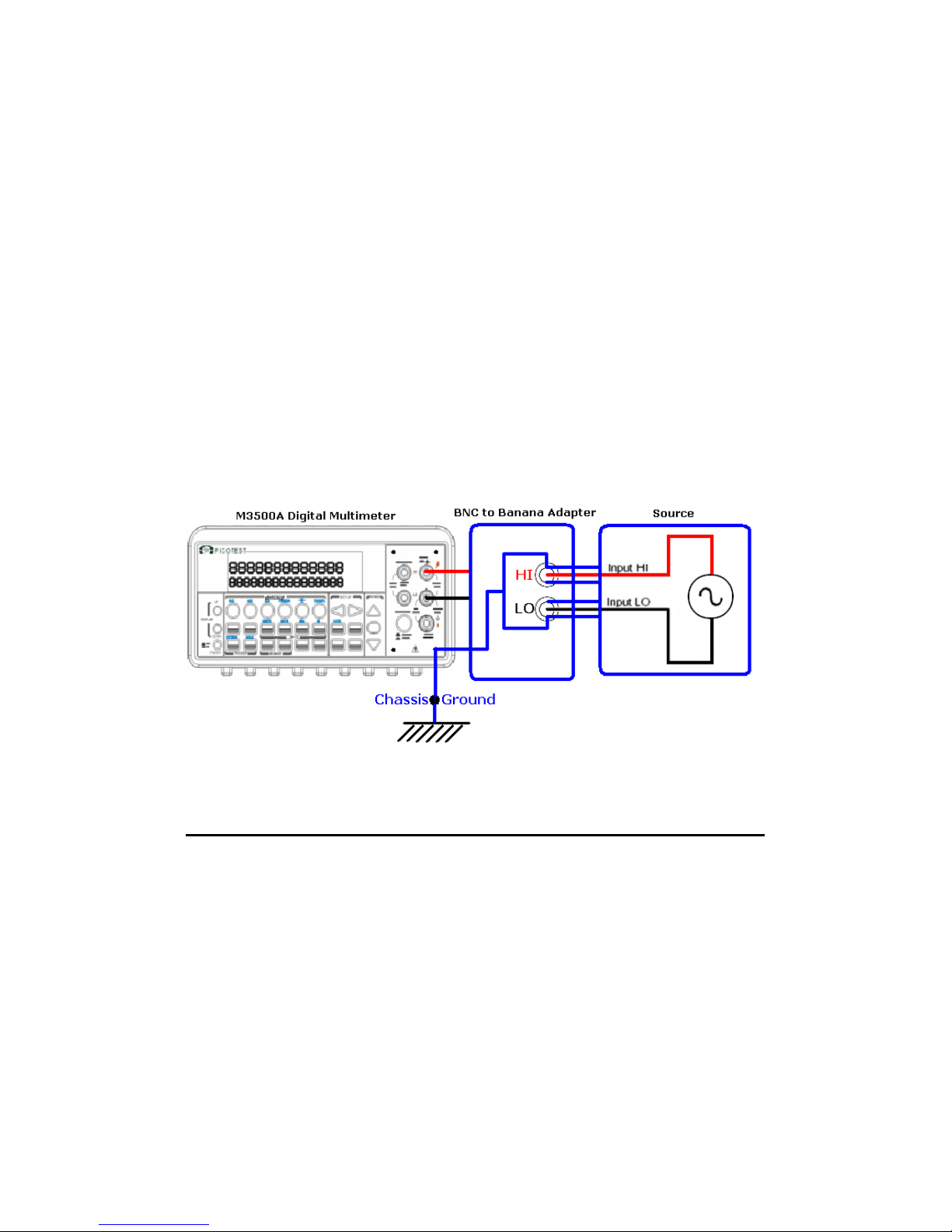
Chassis Ground Terminal:
The chassis ground terminal is used for shielding the noise from
the nature, especially when you want to get a very small signal via
the application of a BNC-to-Banana Adapter. Please refer to the
Figure 2-16.
Figure 2-16
2.3.2 The Display
ATM3500A has a 5x7 dot matrix, dual-display with three-color (White,
Red and Yellow) annunciators for a better view. There are two rows in
the dual-display screen. The upper row displays readings and units. A
maximum 13 characters are allowed for upper row dot-matrix display.
The lower row displays range of the measurements, condition or
information about an ongoing configuration. A maximum 16 characters
are allowed for lower row dot-matrix display. There are additional
29
Page 30
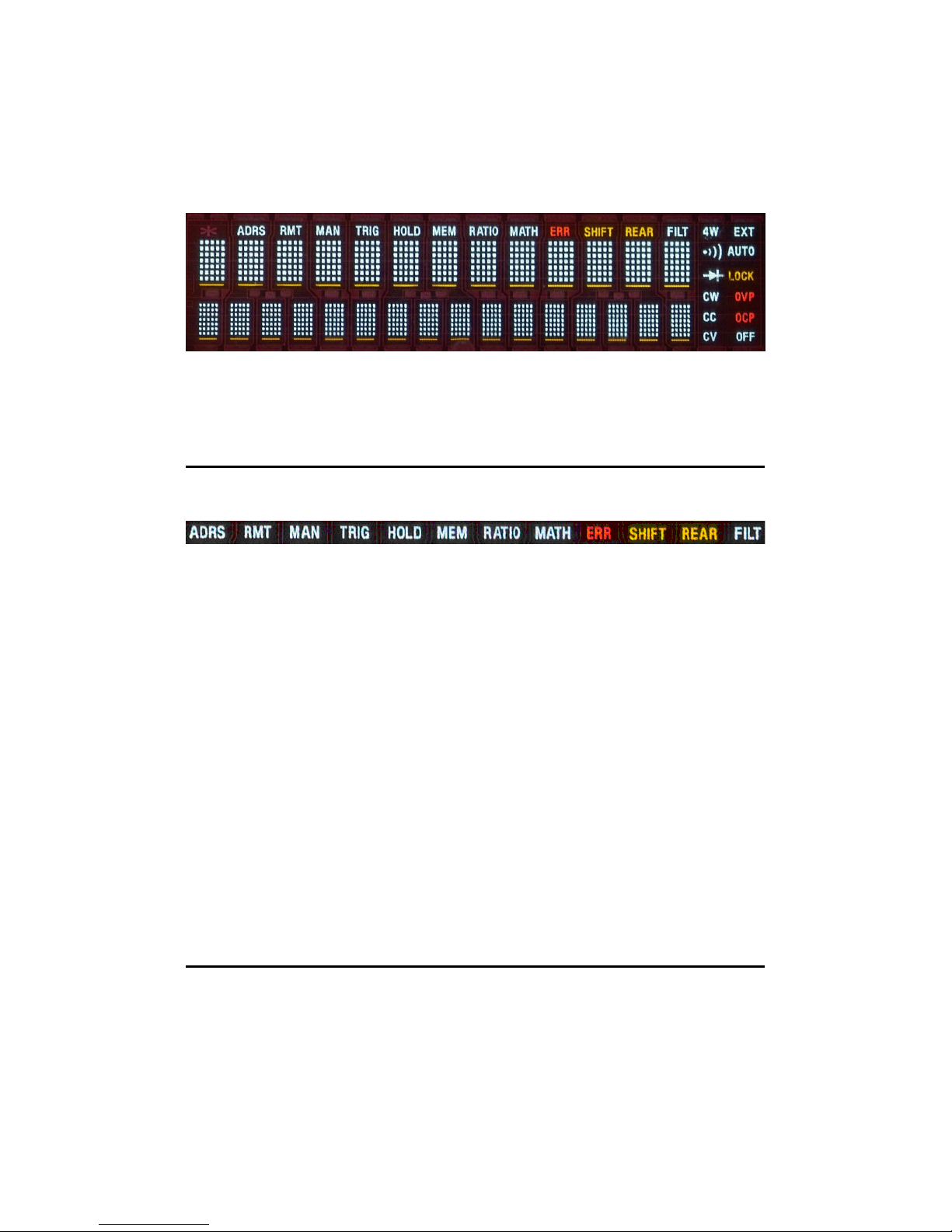
annunciators at upper side and right side of the display screen for
indicating the state or the condition of an ongoing measurement. They
are explained individually in the following sections.
Figure 2-17
2.3.2.1 Annunciators at Upper Side
Figure 2-18
ADRS: Indicates the multimeter is controlled via GPIB Interface.
RMT (REMOTE): Indicates the remote state. (USB Interface)
MAN: Indicates the manual range is taken.
TRIG: Shows the single triggering is enabled.
HOLD: Indicates reading hold function is enabled.
MEM: Indicates the using of internal memory.
RATIO: Indicates the dcv:dcv ratio operation.
MATH: Indicates the “MATH” operation is taken.
ERR: Error occurs.
SHIFT: Indicates SHIFT button is pressed.
REAR: The rear panel input terminal is selected for the
measurement.
FILT: The digital filter is started.
2.3.2.2 Annunciators at Right Side
4W: Indicates 4 –wire mode is selected for resistance
30
Upper Row Display
Lower Row Display
Page 31
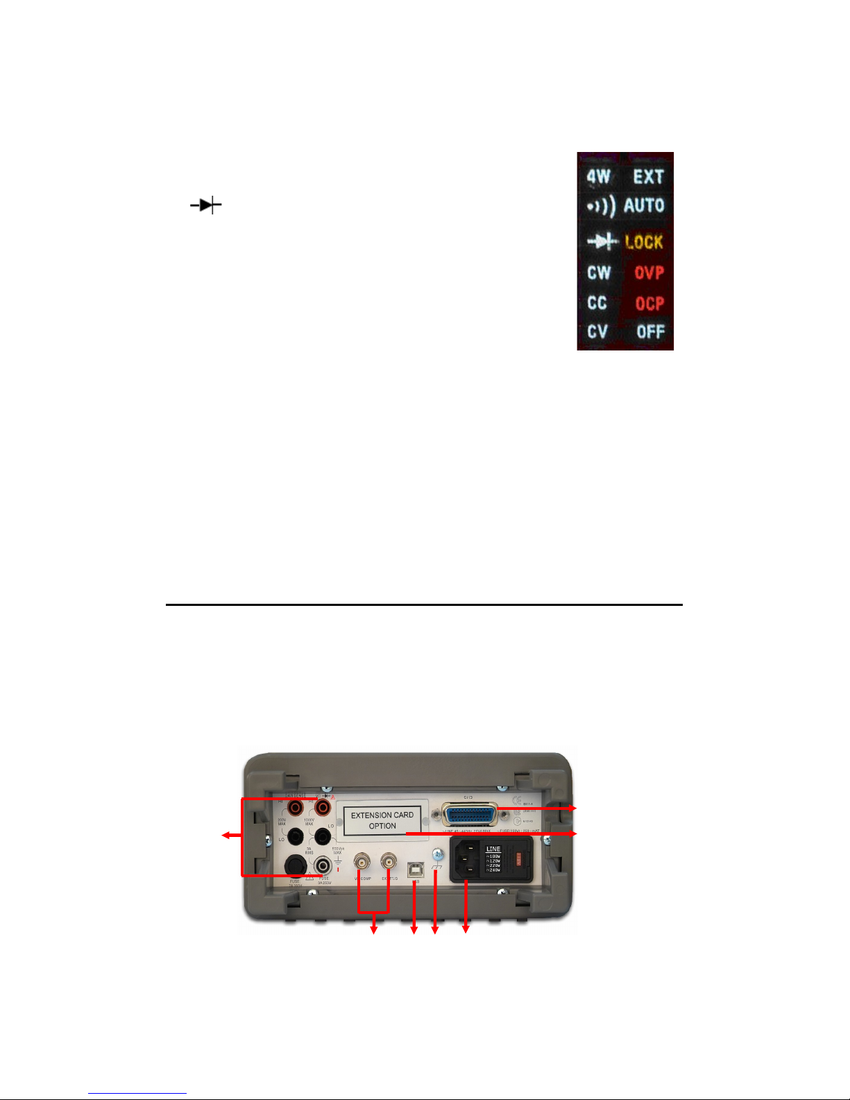
measurement.
●
)
)
): Indicated the continuity testing is enabled.
: Indicates the diode testing operation is taken.
CW: Not used for Model ATM3500A.
CC: Not used for Model ATM3500A.
CV: Not used for Model ATM3500A.
EXT: Indicates the External Trigger Mode is enabled.
LOCK: Indicates the front panel menu operation
is locked.
OVP: Not used for Model ATM3500A.
OCP: Not used for Model ATM3500A.
OFF: Indicates the front panel display is turned off. Figure 2-19
2.3.3 The Rear Panel
The rear panel of the ATM3500A is shown in Figure 2-20. This figure
includes important abbreviated information that should be reviewed
before using the instrument.
31
1
2 3 4 5
7
6
Page 32

Figure 2-20
1. Inserted Connections & Fuse Device:
HI & LO: Used for all measurements, except AC & DC current and
temperature.
LO & I: Used for making DC and AC current measurements.
Rear Fuse: Secures your Meter against damage of strong current
pulse.
2. BNC Connections:
VM COMP: Voltmeter Complete Output Terminal. Outputs a low-true
pulse after the completion of each measurement.
EXT TRIG: External Trigger Input Terminal. Inputs a low-true pulse
from a remote interface.
3.
USB Connection: Connects a remote computer for changing
operation environment instead of the front panel control.
4.
Chassis Ground: Used for shielding the noise from the nature.
5.
Power Module: Contains the AC line receptacle, power line
fuse, and line voltage setting. Configured for line voltages of
100/220V or 120/240V. (Depend on the power utility in your area.)
6.
Option Slot: Designed for installing an optional multi-point
scanner card (Model: M3500-opt01 or M3500-opt09).
7.
Option GPIB (IEEE488 Connection)/RS-232: Connects a
remote computer with an IEEE488 cable or with a DB-9 cable for
changing operation environment instead of the front panel control
(Model: M3500-opt04/M3500-opt06
32
Page 33

3
Basic Measurement
Function
This chapter introduces some basic measurement functions in
ATM3500A. You will learn how to use your ATM3500A multimeter to
measure voltage, current, resistance, frequency, period, continuity,
diode and temperature in this chapter.
3.1 Voltage Measurements (DC & AC)
The ranges for DC voltage measurements in ATM3500A are 100mV, 1V,
10V, 100V and 1000V. For AC voltage measurements, the ranges are
100mV to 750V AC-Coupled
TRMS
, or 1000V peak. Figures 3-1 and 3-
2 show the locations of the buttons needed and message display for
voltage measurement. Figure 3-3 shows the location of the input
terminals on the rear panel.
Warning: Do not apply more than 1000V (peak) to the
multimeter. Applying excess voltage may damage your meter, or cause
possible electric shock or personal injury.
※
Note: To eliminate the thermal EMFs due to the differences between
two metals, use copper leads to connect your source signal to the
meter.
How to measure voltage
1 Selects input signal connections on front or rear
panel.
2 Connect the test leads to the terminals as shown in Figure 3-1(DC)
or Figure 3-2 (AC).
3 Set RESOLUTION of DCV (Refer to 4.1.3), BAND WIDTH of ACV
33
Page 34
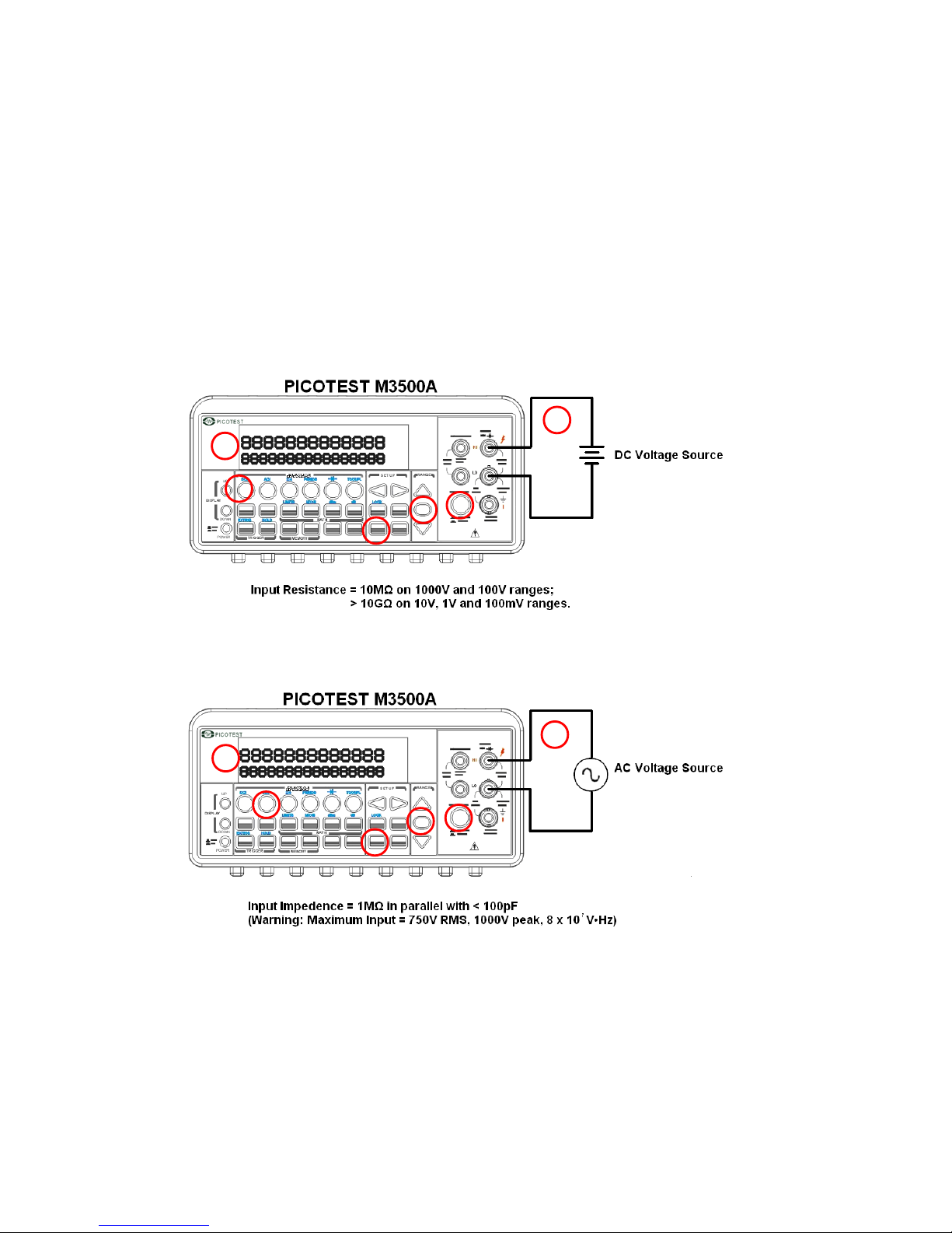
(Refer to 4.1.2.1) or skip this step if default is to be used.
4 Press DCV or ACV button for DC or AC voltage measuring.
5
6 Select the auto-range function by pressing AUTO button on the
front panel or use △ ▽ buttons to select desired range.
7 Connect test leads to your source signal and observe the reading
shown on the display. If the input signal is beyond the allowed
range, an overflow message “OVLD” will be displayed.
Figure 3-1
Figure 3-2
※
Note: The rear panel terminals can also be used via the same
procedures as the front panel terminals. (Refer to Figure 3.3)
34
1
2
3
4
6
2
1
3
4
5
5
6
Page 35
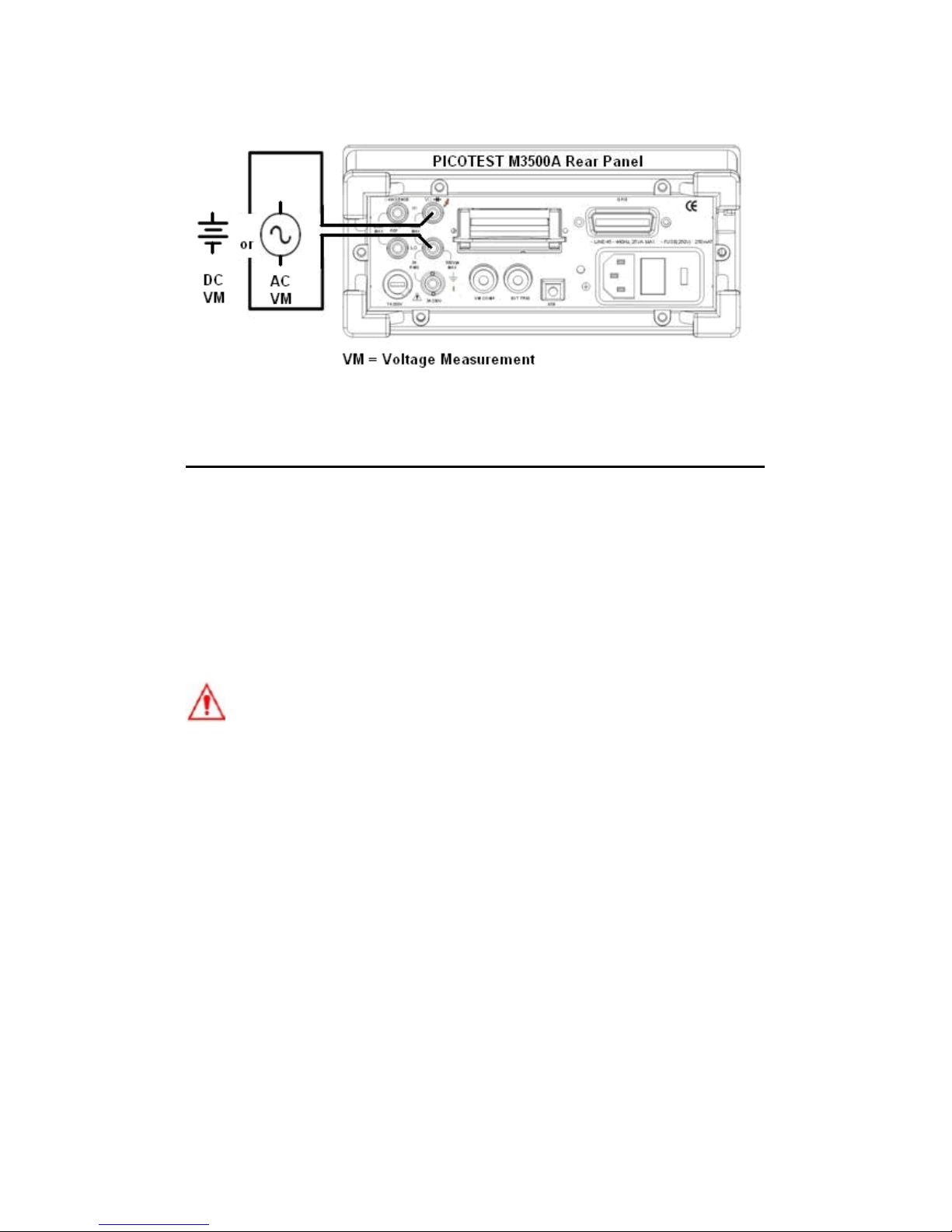
Figure 3-3
3.2 Current Measurements (DC & AC)
The ranges for DC current measurements in ATM3500A are 10mA,
100mA, 1A and 3A. For AC current measurements, the range is 1A
with a sensitivity of 1 μA to 3A AC-Coupled TRMS with a sensitivity of
10μA. Figure 3-4 and 3-5 show you how to measure DC/AC currents
in ATM3500A.
Warning! The maximum input current allowed is 3A, 250V. Do not
apply excess current to your meter to avoid damaging the fuse of
current input.
※ Note: To eliminate the thermal EMFs due to the differences between
two metals, use copper leads to connect your source signal to the
meter.
How to measure current
1
Selects input signal connections on front or rear panel.
2
Connect the test leads to the terminals as shown in Figure 3-4.
35
Page 36
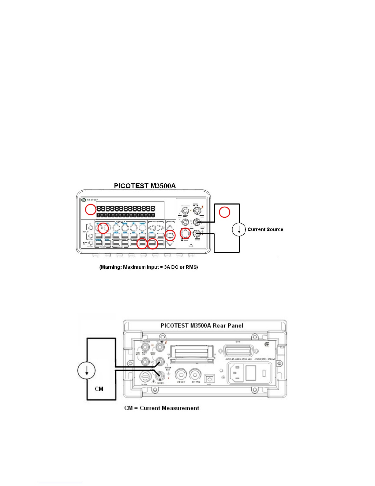
3
Set RESOLUTION of DCI (Refer to 4.1.3), BANDWIDTH of ACI
(Refer to 4.1.2.1) or skip this step if default is to be used.
4
Press SHIFT+DCV or SHIFT+ACV buttons for DCI or ACI
measurement.
5
Select the auto-range function by pressing AUTO button on the
front panel or use △ and ▽ buttons to select desired range.
6
Connect test leads to your source signal and observe the reading
shown on the display. If the input signal is greater than the allowed
range, an overflow message “OVLD” will be displayed.
Figure 3-4
※ Note: The rear terminal panel also can be used via the same
procedures as the front panel. (See Figure 3-5)
Figure 3-5
36
1
2
3
4
5
4
7
6
6
5
Page 37

3.3 Resistance Measurements (2 & 4-wire)
The ranges for resistance measurement are 100 Ω, 1KΩ, 10kΩ,
100kΩ, 1MΩ, 10MΩ, and 100MΩ, with a sensitivity of 100 μΩ (on 100
Ω range.) There are two modes for measuring the resistance: 2-wire
mode as shown in Figure 3-6 and 4-wire mode as shown in Figure 3-
7. With 4-wire mode, the test current is measured from the test
resistance through one pair of the test leads, and the test voltage
across the resistance under test is measured from another set of the
test leads. As a result, the 4-wire mode is more accurate for low
resistance measurements. The trade off is the longer settling time for
4-wire mode.
Figure 3-8 and 3-9 show the input terminal connections on the rear
panel for 2-wire mode and 4-wire mode respectively.
How to measure resistance
1
Selects input signal connections on front or rear panel.
2
Connect the test leads to the terminals as shown in Figure 3-6 (2-
wire) or Figure 3-7 (4-wire).
3
Set RESOLUTION (Refer to 4.1.3) or skip this step if default is to be
used.
4
Press Ω2 button for 2-wire measurement or SHIFT + Ω2 buttons for
4-wire measurement.
5
Select the auto-range function by pressing AUTO button on the
front panel or use △ and ▽ buttons to select the desired range.
6
Connect test leads to your source signal and observe the reading
shown on the display. If the input signal is greater than the allowed
range, an overflow message “OVLD” will be displayed.
37
Page 38
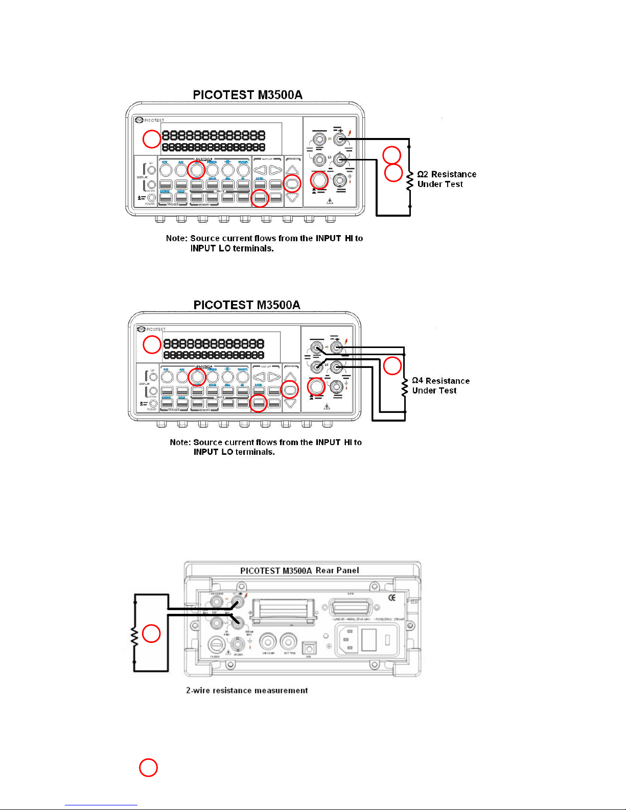
Figure 3-6
Figure 3-7
※
Note: The rear terminal panel also can be
used via the same procedures like the front panel
as shown in Figures 3-8 and 3-9.
Figure 3-8
38
1
2
3
4
6
1
3
4
6
2
5
2
2
2
5
Page 39
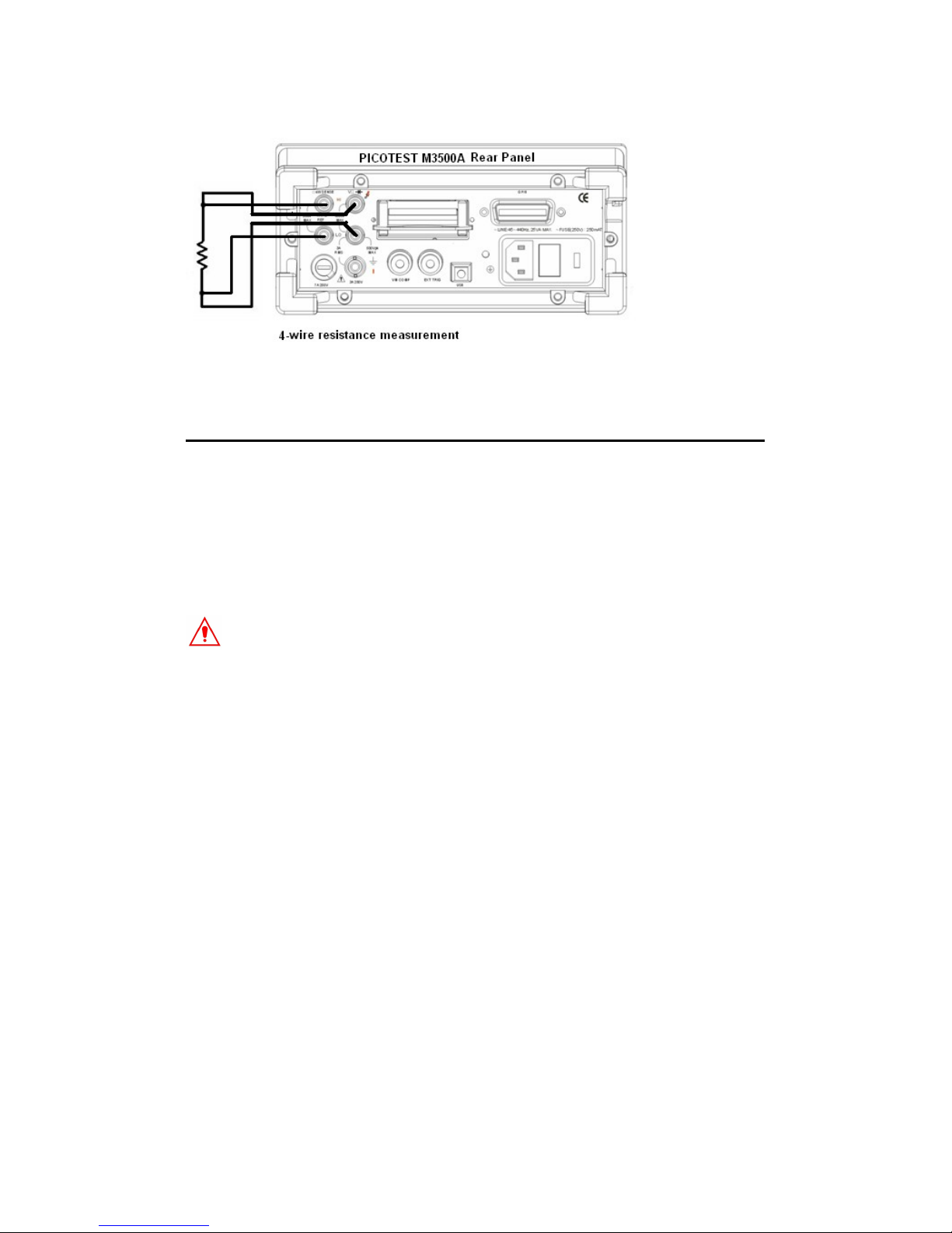
Figure 3-9
3.4 Frequency & Period Measurements
ATM3500A uses an on-board counter with 25MHz to measure the
frequency (period). The measurement band is from 3Hz to 300kHz (or
333 ms to 3.3 μs) and the measurement voltages range from 100mV
to 750 V in AC. The default for “RANGE” is auto-range.
Warning! The maximum input allowed is 1000V. Applying excess
voltage may damage your meter.
How to measure frequency and period
1
Selects input signal connections on front or rear panel.
2
Connect the test leads to the terminals as shown in Figure 3-2.
3
Set RESOLUTION (Refer to 4.1.1) and INPUT JACK. Or skip this step
if default is to be used.
4
Press FREQ button for frequency measurement or SHIFT + FREQ
buttons for period measurement.
5
Select the auto-range function by pressing AUTO button on the
front panel or use △ and ▽ buttons to select the desired range.
39
Page 40

6
Connect test leads to your source signal and observe the reading
shown on the display. If the input signal is beyond the allowed
range, an overflow message “OVLD” will be displayed.
※
Note: The rear terminal panel also can be
used via the same procedures as the front panel.
3.5 Continuity Measurements
ATM3500A uses 1 K Ω range for the continuity measurement. The
meter beeps when the test resistance is less than the threshold
resistance. The default threshold resistance is 10Ω, but you can set the
threshold resistance to anything between 1 Ω and 1 K Ω. The
resistance value set by you is stored in a volatile memory and will be
cleared after the meter has been turned off. The source current for the
continuity measurement is 1 mA.
Warning! The maximum input voltage allowed is 1000 V.
Applying excess voltage may damage the meter and cause
unpredictable hazards.
How to measure the continuity
Selects input signal connections on front or rear panel.
1
Connect the test leads to the terminals as shown in Figure 3-2.
2
Set REConnect the input signal as the following figure.
3
Set threshold resistance via pressing CONFIG + CONT buttons. (Or
skip this step if default resistance is to be used) When ready, press
40
Page 41
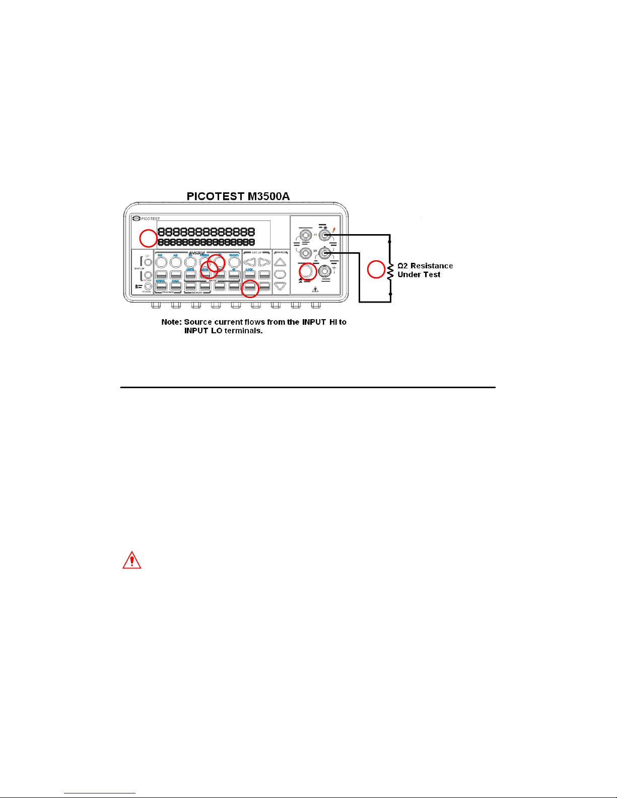
ENTER button.
4
Press CONT button.
5
The measured value will be shown on the display automatically.
Meter “beeps” when measured resistance value is lower than
threshold value.
Figure 3-10
3.6 Diode Measurements
ATM3500A uses a current source of 1 mA for diode testing. The
maximum resolution is 10 μV on a fixed range of 1 V DC. The default
threshold voltage is fixed between 0.3 and 0.8 volts and the reading
rate is fixed at 0.1 PLC (The voltage bound is adjustable from 0.01V up
to 1.2V.). A “Beep” sound will appear when the diode measured value
is in the range.
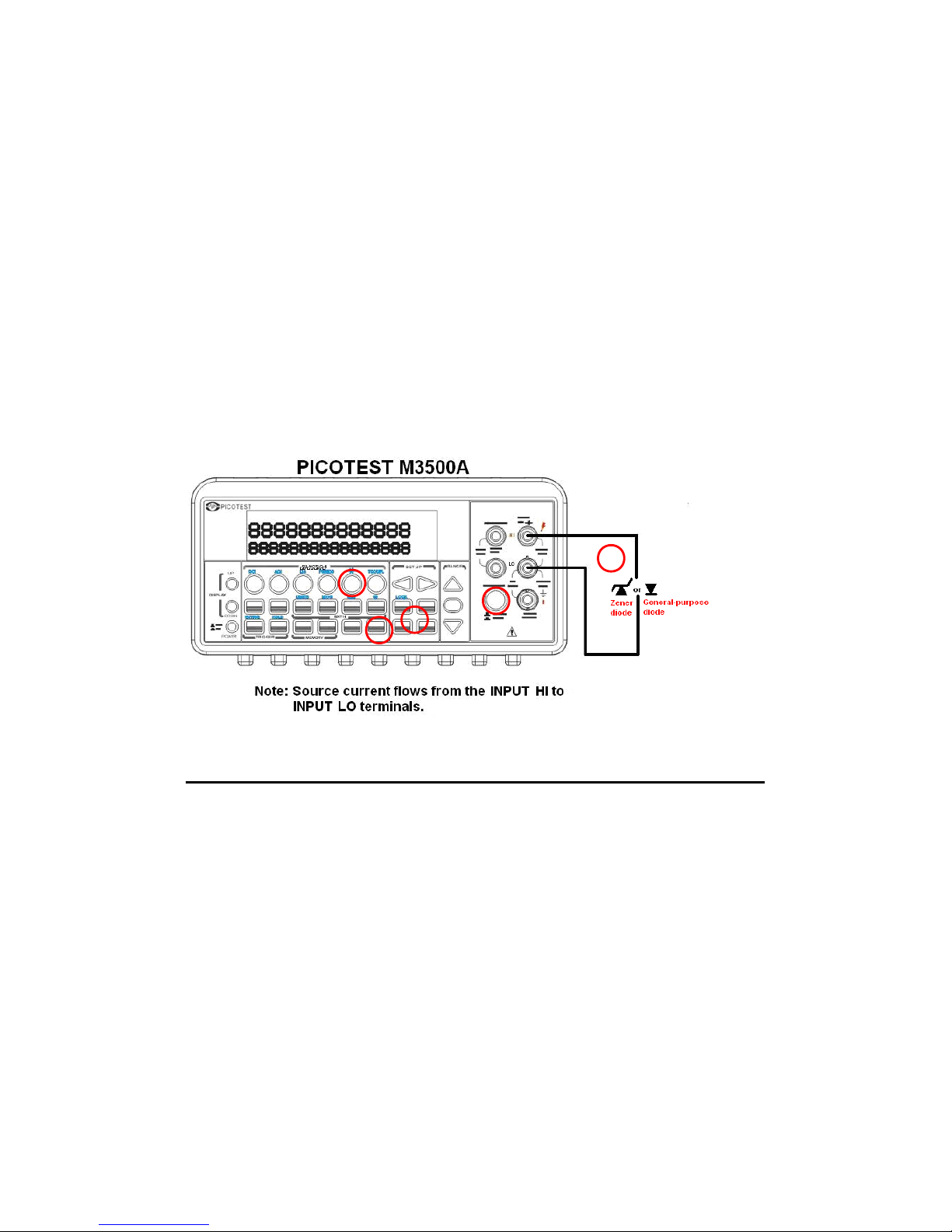
Warning! Positive end of the source signal is to be connected to HI
of the input terminals, and the negative end to LO of the input
terminals.
How to measure diode
1
Selects input signal connections on front or rear panel.
41
1
3
4
3
5
2
Page 42
2
Connect the diode to the terminals. For forward bias, connect the
probe from input terminal “HI” to the positive end of the diode, and
connect the probe from input terminal “LO” to the negative end of
the diode.
3
Set voltage bound via pressing CONFIG + SHIFT + CONT buttons.
When ready, press ENTER. (Or skip this step if you wish to use the
default voltage bound.)
4
Press SHIFT + CONT buttons to select the diode testing function
and observe the reading on the display.
Figure 3-11
3.7 Temperature Measurements
The ATM3500A supports thermocouples and resistance temperature
detector (RTD) types of probes. For thermocouples, ATM3500A
supports 7 types: E, J, K, N, R, S and T. Please refer to Table 3-1 for
their temperature ranges. Be sure that the temperature function is
configured for the right sensor type before making measurements
(Refer to 4.1.8 for how to make the sensor configuration).
In general, RTDs have a better accuracy and long-term stability than
thermocouples. The default RTD type in ATM3500A is PT100
(Temperature Range: -200~850) and the thermocouple is type K.
42
1
3
4
2
4
Page 43
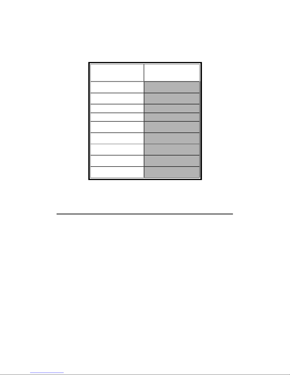
Table 3-1
(Temperature Ranges for Each Thermocouple Type)
Sensor Type Temperature
Range(°C)
B 600~1820
C 0~2316
E -250~1000
J -210~1200
K -200~1372
N -200~1300
R 0~1767
S 0~1767
T -250~400
3.7.1 Thermocouple Measurements
Connect the thermocouple adapter to the banana jacks on the front
panel. The difference between each type is subject to the patch
thermal leads.
※
Note: Only connection via the front panel can be used for
temperature measurements.
How to measure thermocouple
1
Use terminals switch to select terminals on the front panel.
2
To measure thermocouple, you must use a thermocouple adapter
and a sensor, (K type for example), with the low thermal patch lead
43
Page 44
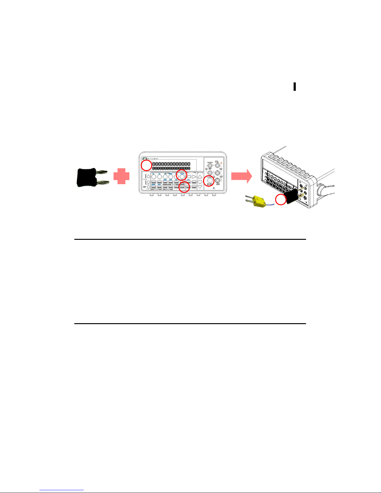
as shown in Figure 3-12.
3
Configure the thermocouple type and unit using CONFIG + SHIFT +
TEMP, such as K TYPE and ºC. When ready, press ENTER button.
4
Press SHIFT + TEMP buttons.
5
Take the reading on the display.
Figure 3-12
3.7.2 RTD Measurements
There are three kinds of temperature measurements with RTDs: 2-
wire, 3-wire and 4-wire measurements. You will find connection
instructions and measuring procedures in the following sections.
3.7.2.1 2-Wire RTD Measurements
How to measure temperature with 2-Wire RTD
The following Figure 3-13 shows theory diagram of 2-Wire RTD
measurement.
1
Use terminals switch to select front terminals.
2
Insert a specified adapter into the front terminals. Connect the low
44
3
5
4
1
2
Page 45
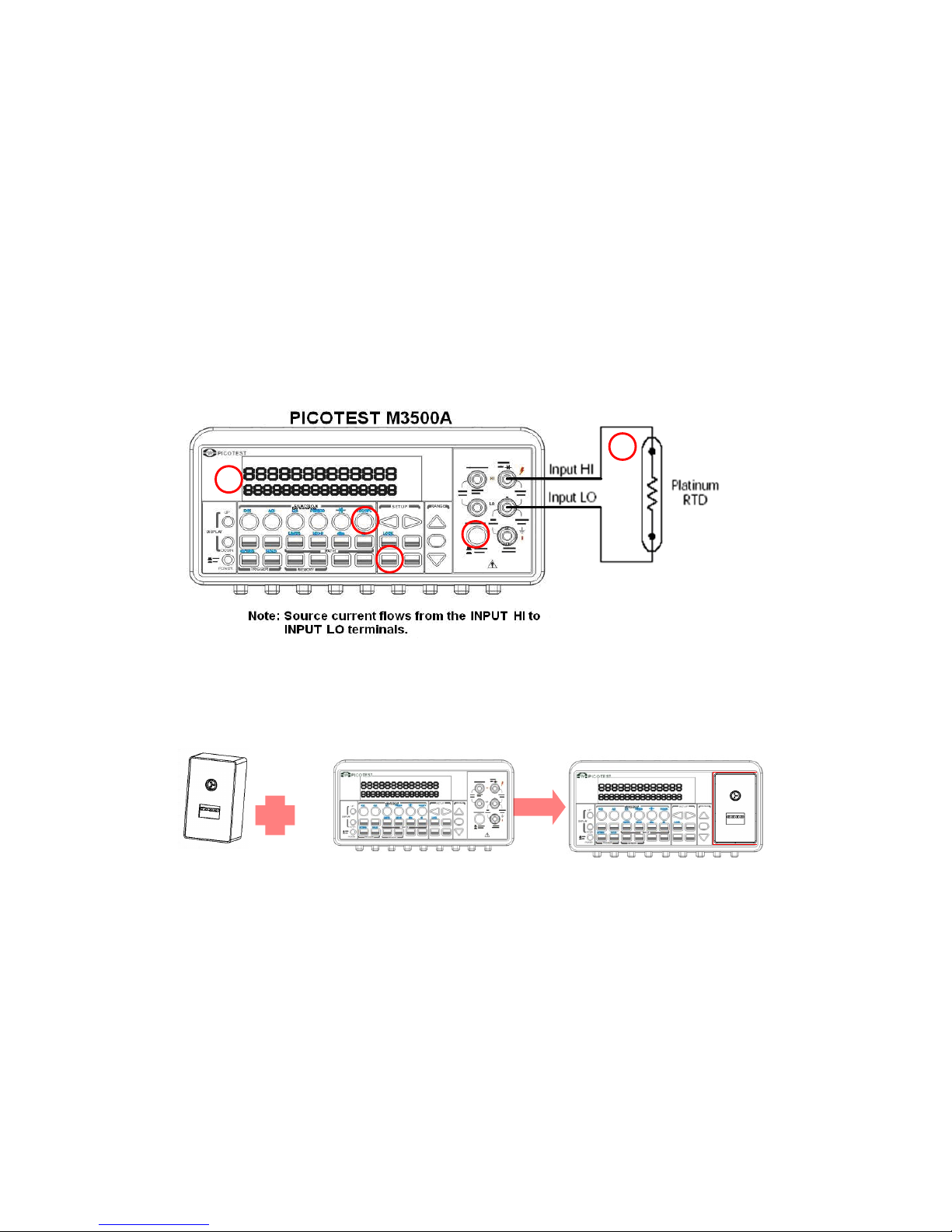
thermal patch leads to the adapter as shown in Figure 3-14.
3
Configure sensor type, transducer (2W) and unit using CONFIG +
TEMP and ◁ or ▷. When ready, press ENTER button. For more
information, refer to the section 4.1.8.
4
Press TEMP button.
5
Place RTD in the desired position and take the reading on the
display.
Figure 3-13
45
1
2
4
5
3
1
2
3
Page 46
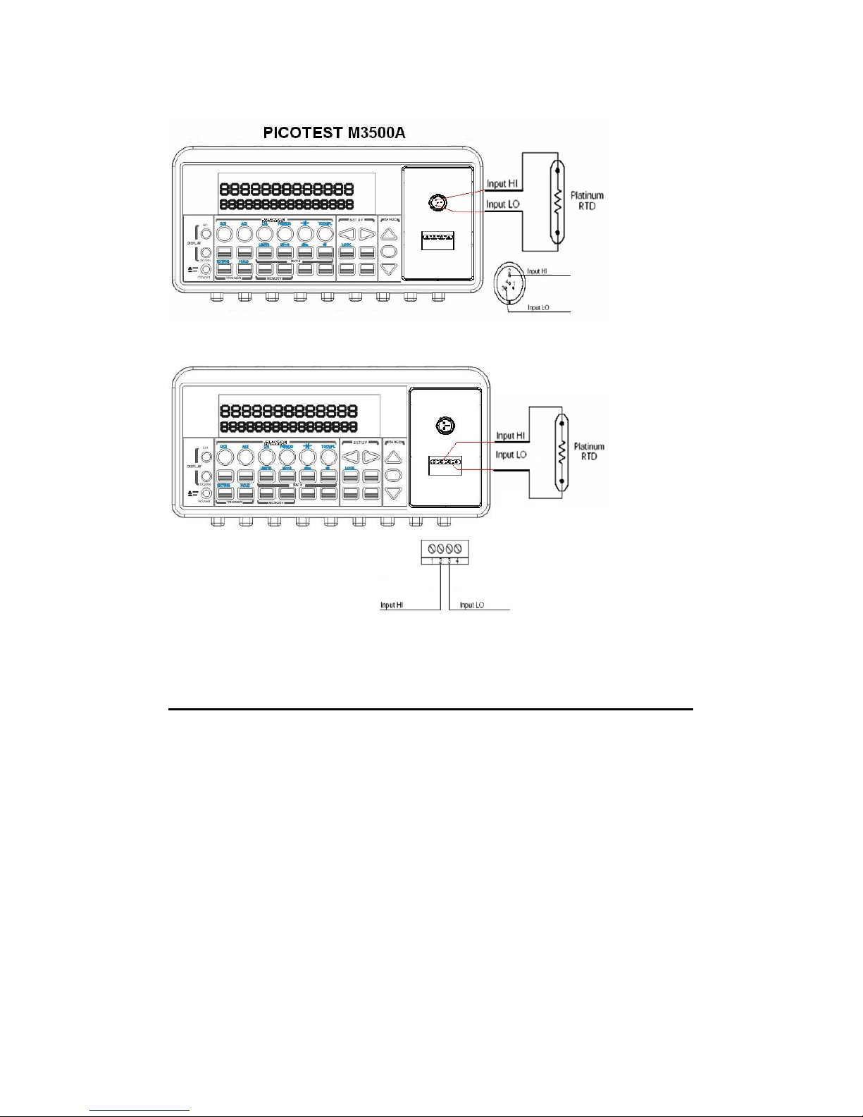
Figure 3-14
3.7.2.2 3-Wire RTD Measurements
How to measure temperature with 3-Wire RTD
The following Figure 3-15 shows theory diagram of 3-Wire RTD
measurement.
1
Use terminals switch to select front terminals.
2
Insert a specified adapter into the front terminals. Connect the low
thermal patch leads to the adapter as shown in Figure 3-16.
46
4
5
Page 47
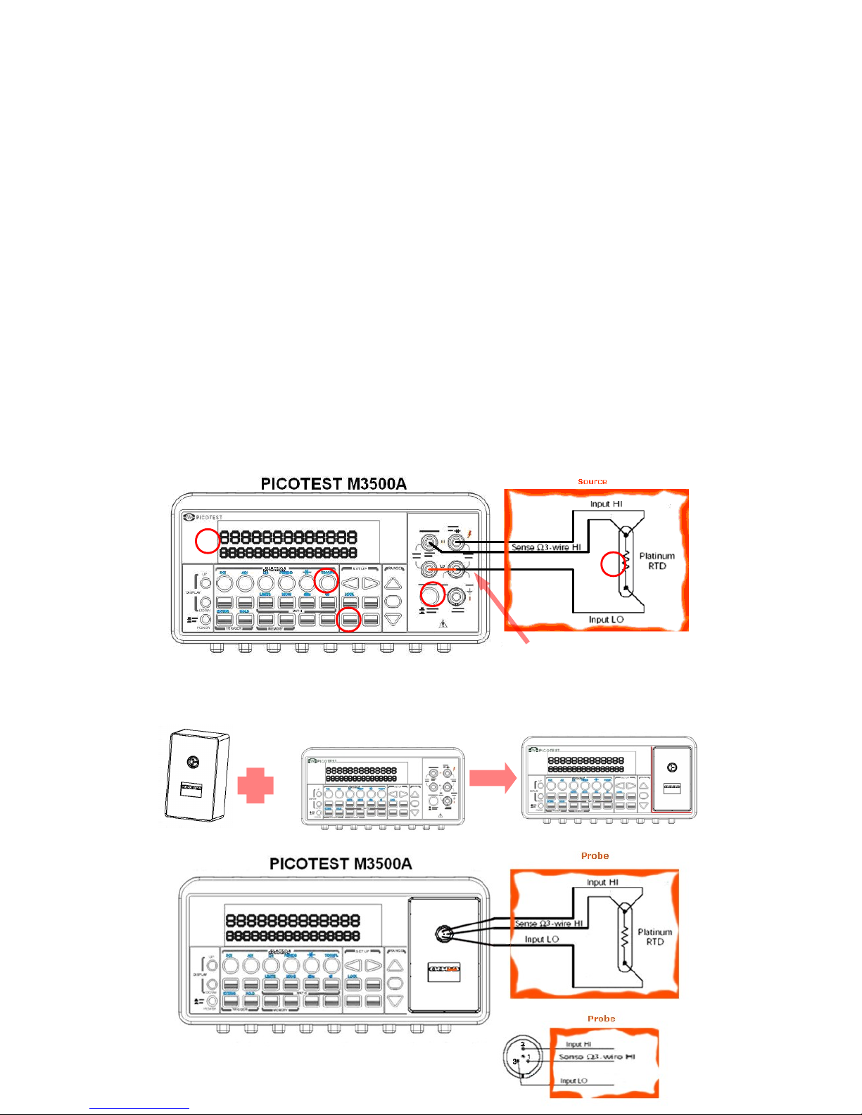
3
Configure sensor type, transducer (4W) and unit using CONFIG +
TEMP and ◁ or ▷. When ready, press ENTER button. For more
information, refer to the section 4.1.8.
4
Press TEMP button.
5
Place RTD in the desired position and take the reading on the
display.
※
Note: When you conduct the 3-wire RTD
measurement, the input LO and sense LO have to be connected in
short condition.
※
Note: “Source” means RTD Probe or RTD Simulator.
Figure 3-15
47
1
2
3
5
5
4
4
1
2
3
In Short Condition
Page 48
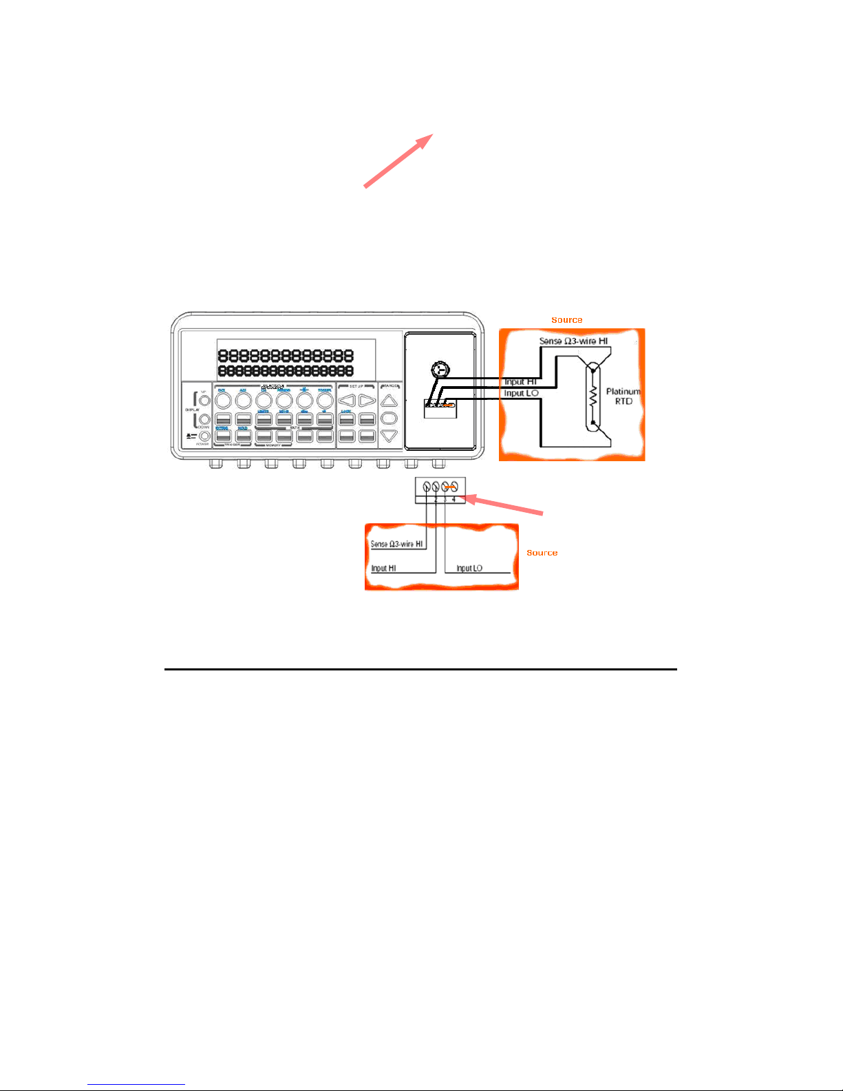
Figure 3-16
3.7.2.3 4-Wire RTD Measurements
How to measure temperature with 4-Wire RTD
The following Figure 3-17 shows theory diagram of 4-Wire RTD
measurement.
1
Use terminals switch to select front terminals.
2
Insert a specified adapter into the front terminals. Connect the low
thermal patch leads to the adapter as shown in Figure 3-18.
3
Configure sensor type, transducer (4W) and unit using CONFIG +
48
5
In Short Condition
In Short Condition
Page 49
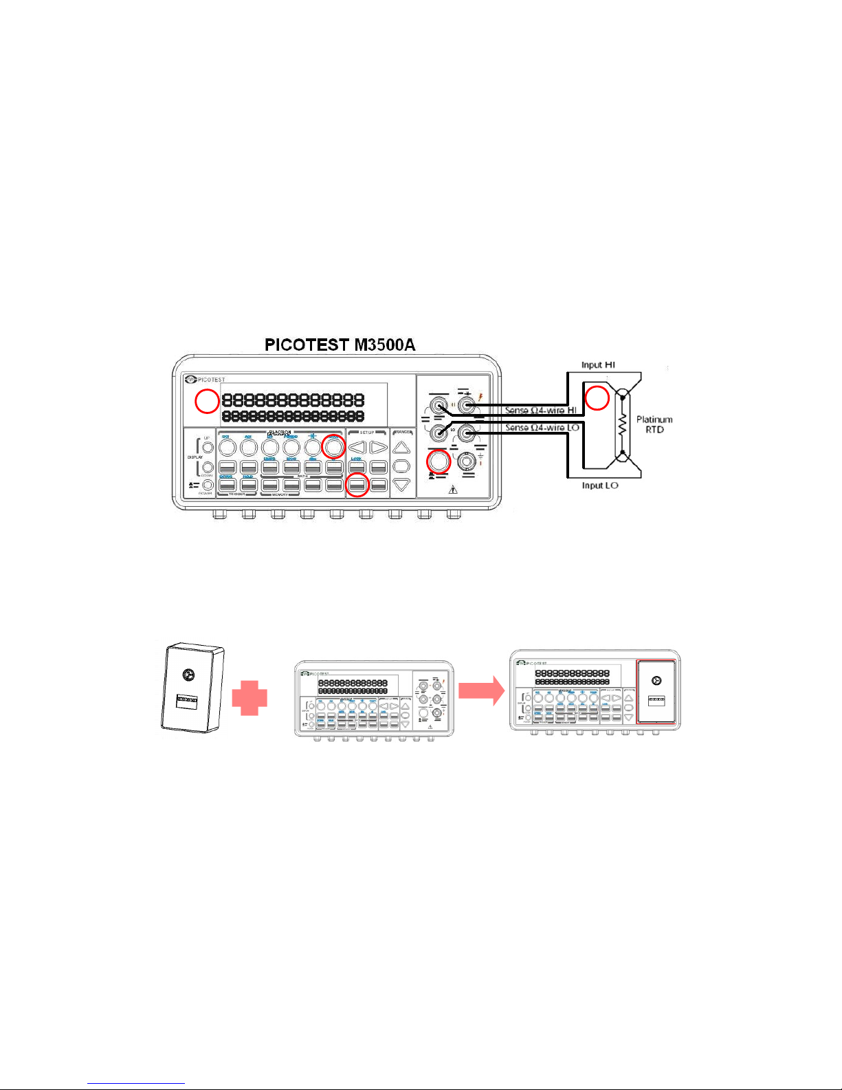
TEMP and ◁ or ▷. When ready, press ENTER button. For more
information, refer to the section 4.1.8.
4
Press TEMP button.
5
Place RTD in the desired position and take the reading on the
display.
Figure 3-17
49
1
2
3
5
5
4
4
1
2
3
Page 50
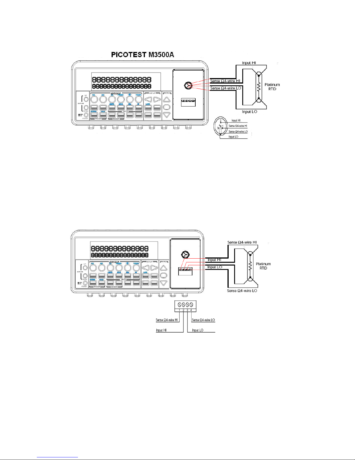
Figure 3-18
50
5
Page 51

4
Front Panel Operations
This chapter contains information about how to change the parameters
and settings for your measurements and all the details about each
feature and function.
4.1 Measurement Configuration
The following information will guide you through ways to configure
measurement functions. It provides you the flexibility to change any
parameter in any measurement function when needed, including ADC
setting, filter, resolution setting (digits), DC input resistance, threshold
resistance (continuity), range (manual & auto), rate (integration time),
sensor type for temperature measurements, remote interface selection
and input terminal switch.
4.1.1 Set ADC (Auto Zero)
Zero
The purpose of Auto Zero function is used for minimizing the offset
influence on your measurements. When Auto Zero is enabled,
ATM3500A takes the input signal reading as a base value and then
internally disconnects the input signal, and takes an offset reading (a
null offset). It then subtracts the offset from the base to get an
accurate measurement.
Displayed reading = Base value (input signal) – Offset value
When the Auto Zero is enabled the meter takes an offset reading for
each subsequent measurement. However, when Auto Zero is disabled,
the meter only takes one offset reading each time when you change
the function settings.
51
Page 52
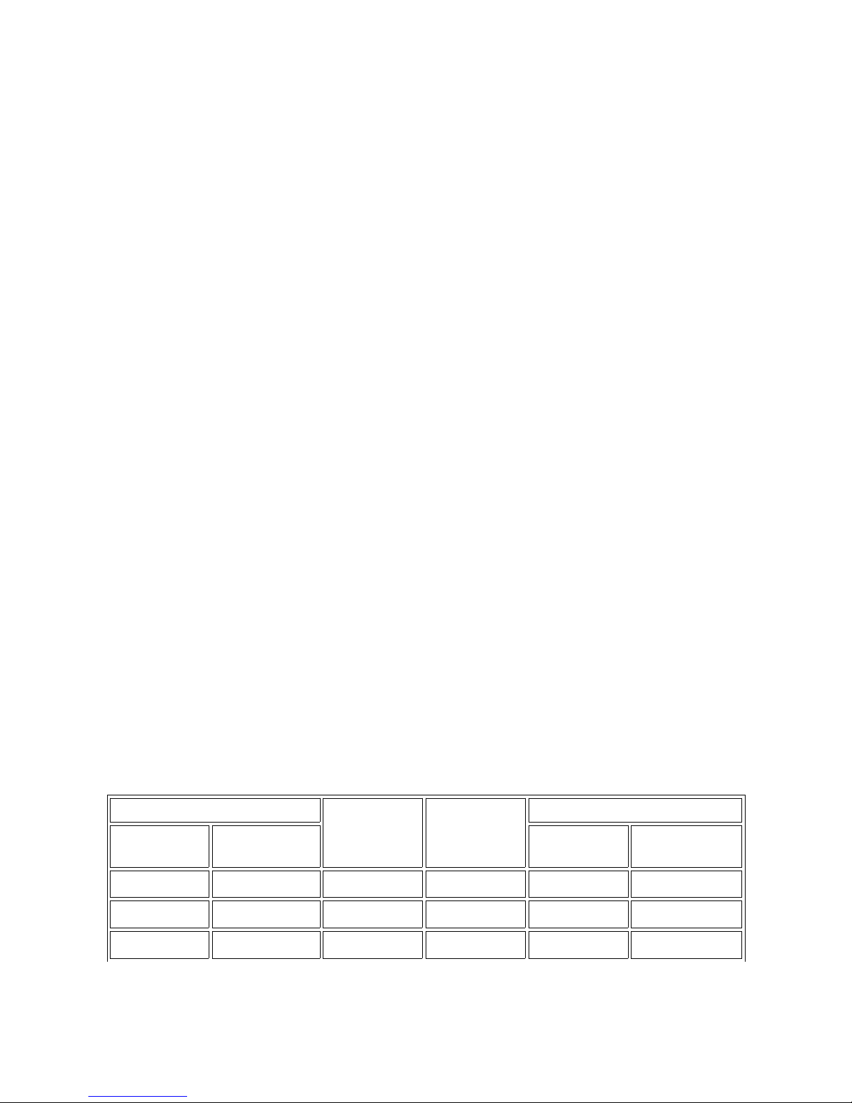
Defaults
The default settings for Auto Zero are enabled. The user selected
values for Auto Zero are stored in a volatile memory and the default
settings will be restored when the meter is power-off.
How to set Auto Zero
You can change the Auto Zero setting through the front panel or
through the remote interface operation.
Front Panel Operation
The following steps show how to set Auto Zero directly through the
front panel.
Be aware that Auto Zero setting is always affected by the resolution
setting. Whenever the resolution is altered, Auto Zero may be changed
accordingly. The relation between resolution and Auto Zero is shown in
Table 4-1.
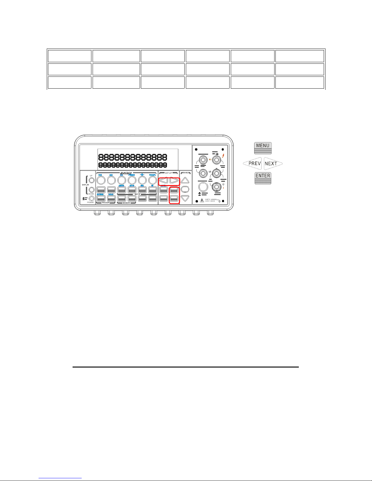
Press MENU and then ENTER on SET ADC. If “SET ADC” is not shown
on the display, use ◁ and ▷ buttons to locate it. Press ENTER on ZERO.
Again, use ◁ and ▷ buttons to locate it if it is not shown on the display.
Press ENTER on AUTO ZERO option and then use ◁ and ▷ to the “ON”
or “OFF”. Press “ENTER” by your choice. The locations of these buttons
are shown with red rectangle frames in Figure 4-1.
Procedures: MENU→SET ADC → ZERO→ AUTO ZERO {ON|OFF}
Table 4-1
Integration Time(PLC)
Resolution Auto
Zero
Remote Digits Displayed
DEFAULT
COMPATIBLE
DEFAULT
COMPATIBLE
0.02 0.02
Fast 4 ½ digits
Off 4 ½ 4 ½
0.1 1
Slow 4 ½ digits
On 4 ½ 5 ½
0.1 0.1
Fast 5 ½ digits
Off 5 ½ 5 ½
52
Page 53
1 10
Slow 5 ½ digits
On 5 ½ 6 ½
1 10
Fast 6 ½ digits
On 6 ½ 6 ½
10 10
Slow 6 ½ digits
On 6 ½ 6 ½
※
Note: To change resolution, refer to Section 4.1.3: Resolution
Setting in this chapter.
Figure 4-1
Remote Interface Operation
To set Auto Zero through the remote interface, use the following
commands:
SENSe:ZERO:AUTO {OFF|ONCE|ON}
The OFF and ONCE parameters have a similar effect. Auto Zero OFF
doesn’t issue a new offset measurement. However, Auto Zero ONCE
issues an immediate offset measurement.
4.1.2 Filter
Filter is used to remove noises in measurement readings. ATM3500A
is equipped with two types of filters: AC filter and digital filter. AC filter
is for AC measurements only. It also affects the speed of the
53
Page 54

multimeter to yield a measurement reading. Digital filter further
stabilizes the measurement readings by averaging. Both of them are
described in detail in the subsequent sections respectively.
4.1.2.1 AC Filter
Definition:
You are allowed to set the bandwidth for selecting one of the three AC
filters (Slow, Medium and Fast), in order to achieve either higher
accuracy in low frequency measurements or faster AC settling time.
Defaults
The factory default is 20 Hz (Medium). You can select the filter type as
you wish when setting bandwidth value. The selection is stored in a
volatile memory and the default setting will be restored when the
meter is power-off.
Table 4-2
Bandwidth AC Filter
Time
( seconds per reading)
3 Hz ~ 300 KHz Slow 7
20 Hz ~ 300 KHz Medium 1
200 Hz ~ 300 KHz Fast 0.1
How to set AC Filter in AC measurements:
You can set the AC Filter either through the front panel operation or
through the remote interface operation.
Front Panel Operation
Press CONFIG + ACV button. Use ◁ and ▷ buttons to locate “BAND
WIDTH” submenu, and then press ENTER to select it. Look for the
desired bandwidth using ◁ and ▷ buttons. Then press ENTER on your
selection. There are three options: 3Hz, 20Hz and 200Hz. The locations
of these buttons are shown with red rectangle frames in Figure 4-2.
54
Page 55
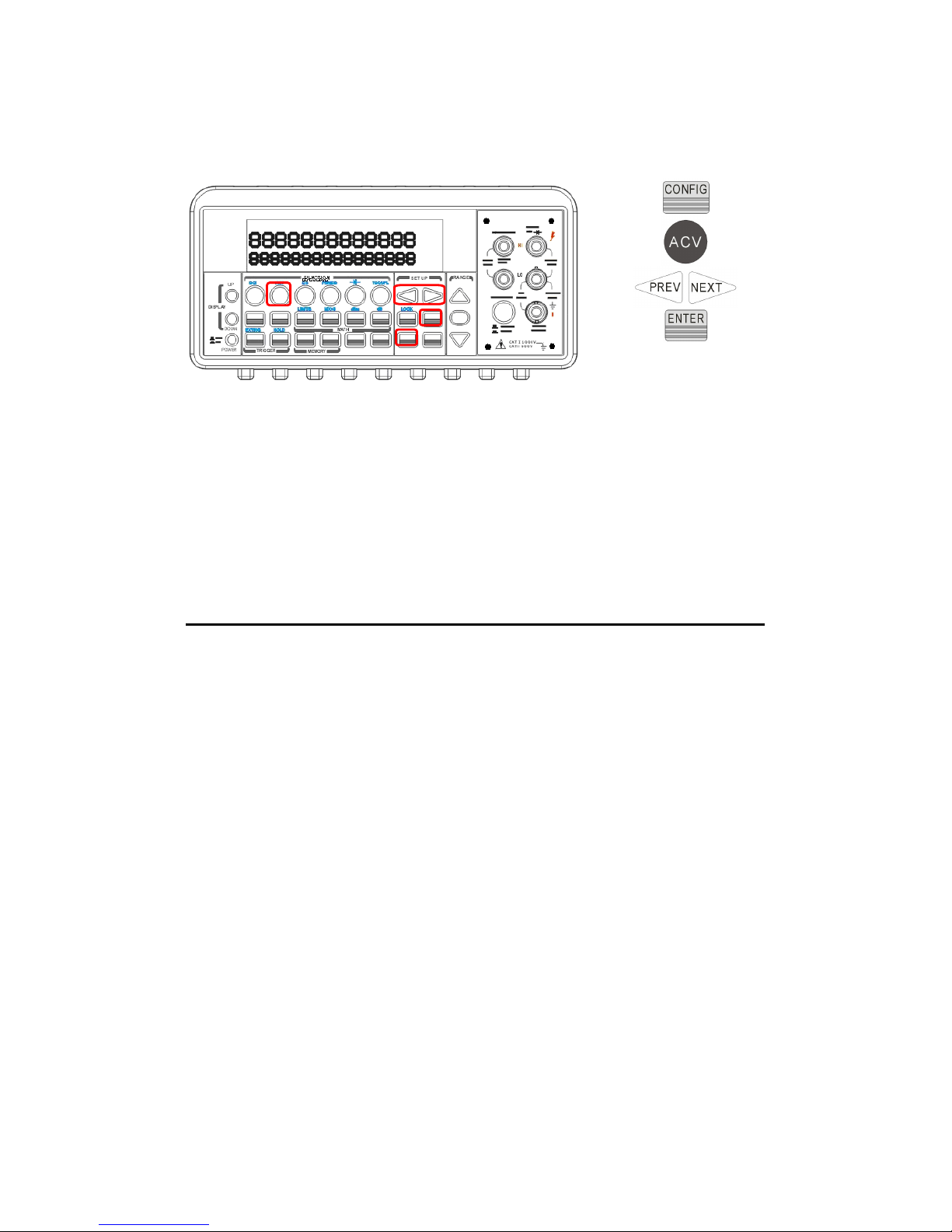
Figure 4-2
Remote Interface Operation
From your PC terminal, use the following command to specify the filter
type:
DETector:BANDwidth {3|20|200|MIN|MAX}
4.1.2.2 Digital Filter
Definition:
ATM3500A uses an averaging digital filter to yield a reading for display
from a specified number of measurement readings in the past.
Treading conversions The past measurement readings k of memory.
The number may be in the range of 2 to 100. You may select one of
the two modes of digital filter operations:User can select the averaging
mode from Moving Average and Repeating Ave
The moving average filter puts the specified number of reading
conversions in a first-in, first-out order. The very first measurement
reading simply fills up the stack. To yield a reading for display, the
filter produces an average of the stacked measurement readings co the
new readw measurement reading is available and replaces . Because
the newesren the stack., after the specifiaverage mode, the multimeter
waits for the measurement reading stack to fill up and then take an
55
Page 56

average to produce a reading for dislay.filter takes the specified
number of reading conversion, averages them and produces a reading.
It then flushes the stack and starts over with an new User can set the
number to anything from 1 to 100Consequentter yields one reading for
display every specified number measurement r
Digital filter is not available for diode, continuity, frequency and period
measurements.
Default
The digital filter is enabled and is in moving average mode with 10
readings by default.
How to enable/disable digital filter
Press FILTER button to switch the digital filter function.
The “FILT” anunnciator indicates the state of the digital filter. When it
is lit, the filter is enabled.
How to configure digital filter fo
You can configure the digital Filter either through the front panel
operation or through the remote interface operation.
Front Panel Operation
For READINGS setting, please press CONFIG and then FILTER button
for selecting READINGS. Press ENTER to access. Use ◁, ▷, △ and ▽
buttons to set the READINGS (from 2 to 100) in order to get an
average value. Press ENTER when it’s ready.
For MODE setting, please press CONFIG and then FILTER button for
selecting MODE. Press ENTER to access. Use ◁, ▷ to select MOVING
AVG. or REPEAT AVG.. Please ENTER to confirm.
Press FILTER button to enable or disable this function.
Remote Interface Operation
Use the following commands to set your digital filter:
SENSe:AVERage:TCONtrol {MOVing|REPeat}
SENSe:AVERage:TCONtrol?
SENSe:AVERage:COUNt {<value>|MINimum|MAXimum}
SENSe:AVERage:COUNt? [MINimum|MAXimum]
56
Page 57

SENSe:AVERage:STATe {OFF|ON}
SENSe:AVERage:STATe?
4.1.3 Resolution Setting (Digits)
Definition
Resolution with the number of digits on a multimeter is visible. You can
select the resolution for a specific measurement. The choices for the
resolution setting are: fast 4.5, slow 4.5, fast 5.5, slow 5.5, fast 6.5
and slow 6.5. For a higher accuracy, you can select 6.5 digit resolution.
For a faster measurement, you can select 4.5 digit resolution.
The resolution setting applies to all math operations under the selected
measurement function. The selected value is stored in a volatile
memory and the setting is only valid for the current measurement
function. You can select different resolution for different measurement
function.
Default
The default value for the resolution is slow 5.5 digit and the default
value will be restored when the meter has been turned off or after a
remote interface reset. The user selected value for the resolution
setting is stored in a volatile memory and the setting is only valid for
the current measurement function. Please refer to Table 2-1 on page
24.
How to set the resolution
The resolution can be set either through the front panel or the remote
interface operation.
Front Panel Operation
There are two ways to set the resolution. The locations of the buttons
are shown with red rectangle frames in Figure 4-3.
57
Page 58

A.
First select your desired measurement function by pressing one of
the function buttons located on the first row of your meter's front
panel.
Press DIGITS button to select your desired resolution for your
measurement. You can press DIGITS button several times to see
how the resolution setting changes from 4.5, 5.5 to 6.5.
※
Note: When using Method A to set the resolution, your options are
4.5 (slow), 5.5 (slow) and 6.5 (fast).
B.
Press CONFIG and then select a function as you wish from DCV, DCI
(SHIFT +DCV), Ω2, Ω4 (SHIFT + Ω2), FREQ and PERIOD (SHIFT +
FREQ).
Press ENTER on RESOLUTION submenu. If it is not shown on the
display, use ◁ and ▷ to locate it.
Use ◁ and ▷ to find your desired resolution. Press ENTER on your
choice.
※
Note: The resolution of AC measurements is fixed at 6.5 digit.
※
Note: The options for frequency and period measurements are 4.5
(slow), 5.5 (slow) and 6.5 (slow).
58
Page 59
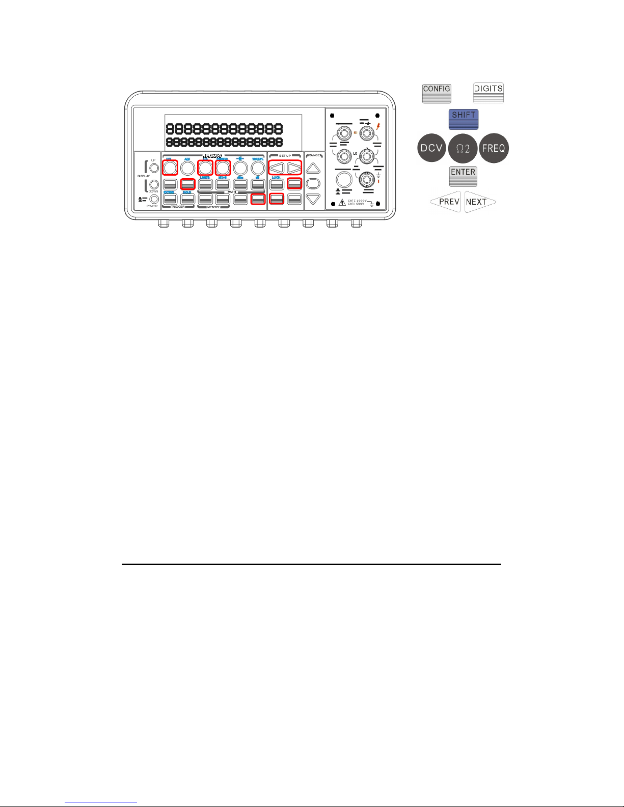
Figure 4-3
Remote Interface Operation
Use the following commands on your PC terminal to set the resolution
for your measurement.
CONFigure:<function> <range>,<resolution>
MEASure:<function>? <range>,<resolution>
SENSe:<function>:RESolution <resolution>
You can specify the resolution in the same units as the measurement
function, not in number of digits. For instance, specify the resolution in
vots and the frequency in hertz. The examples are in the following.
CONF:VOLT:DC 10,0.001
(4 1/2 digits on the 10 Vdc range)
MEAS:CURR:AC? 1,1E-6
(6 1/2 digits on the 1 A range)
CONF:FREQ 1 KHz,0.1 Hz
(1000 Hz input, 0.1 Hz resolution)
VOLT:AC:RES 0.05
(50 mV resolution on the ac function)
4.1.4 DC Input Resistance
Definition
To reduce the effect of loading errors due to the input resistance,
ATM3500A allows you to select a much larger input resistance (> 10G
Ω) for low input DC voltage (100mV, 1V and 10V) measurements. This
feature is only available for DC voltage measurements and it is not
applicable to other measurement functions.
59
or
Page 60
Default
The default input resistance for all measurements is 10M Ω. Please
refer to Table 2-1 on page 24. The DC input resistance can only be
changed for measurements with 100mV, 1V or 10V range. For 100V
DCV, 1000 V DCV and other measurement functions, the input
resistance is fixed at 10M Ω and can not be changed. Also note that
the user selected value is stored in a volatile memory. The default
setting will be restored after the meter has been turned off.
How to set the DC input resistance
You can set the DC input resistance either through the front panel
operation or through the remote interface operation.
Front Panel Operation
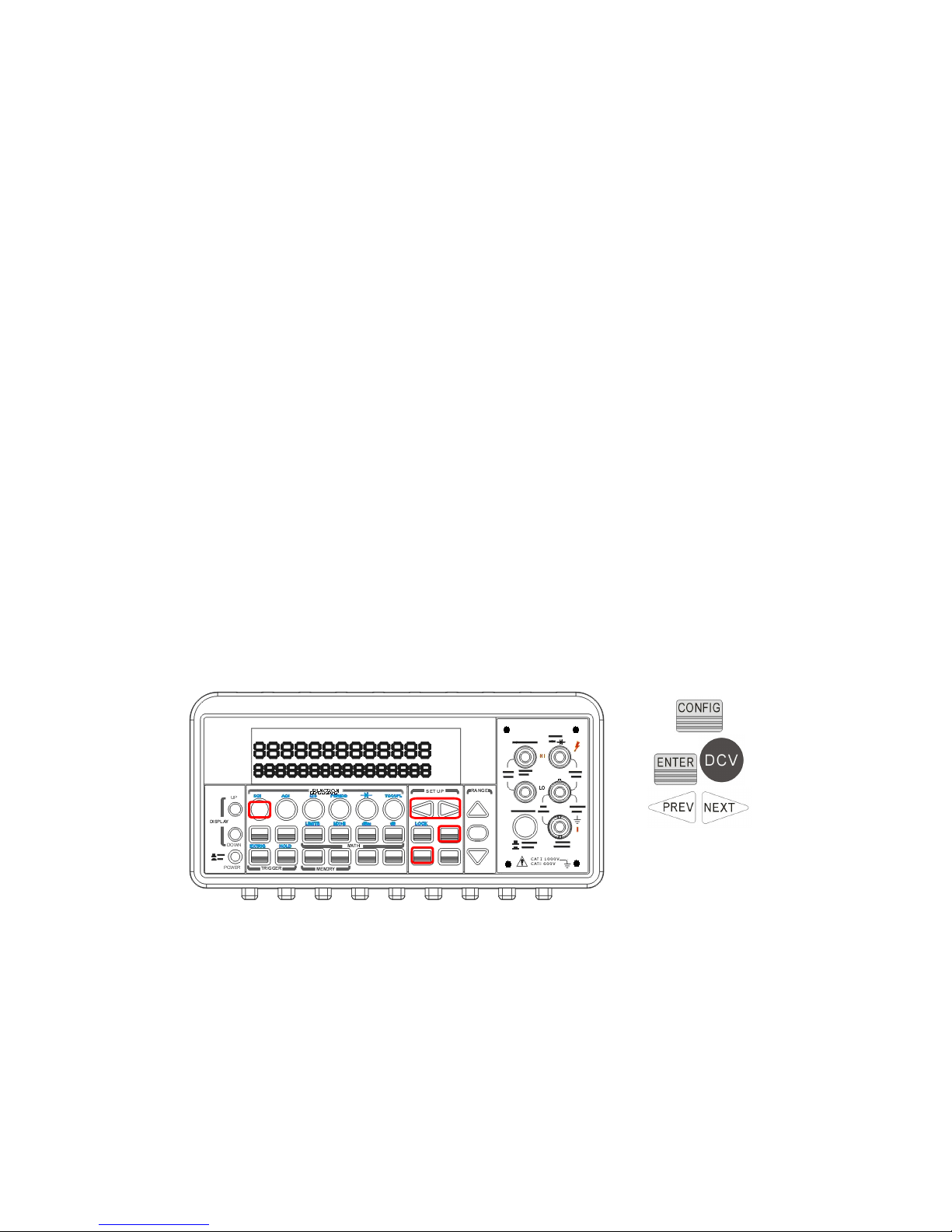
Press CONFIG + DCV , and then use ◁ and ▷ buttons to locate “INPUT
R” option. Press ENTER to select it. Then select desired value for the
input resistance by pressing ◁ or ▷ button. Press ENTER to choose it.
Two values are available: 10M Ω or > 10G Ω. The locations of these
buttons are shown with red rectangle frames in Figure 4-4.
Figure 4-4
Remote Interface Operation
The automatic input resistance mode can be enabled / disabled. With
AUTO OFF (default), the input resistance is fixed at 10MΩ for all
ranges. With AUTO ON, the input resistance is set to >10GΩ for the
three lowest DC voltage ranges (100mV, 1V and 10V). Use the
60
Page 61
following command from your PC terminal to disable the auto input DC
resistance setting (the result is a fixed input DC resistance at 10M Ω
for all measurements.)
INPut:IMPedance:AUTO {OFF | ON}
4.1.5 Threshold Resistance (Continuity)
Definition
When testing continuity, the beeper goes off when the measured
resistance is less than the threshold resistance. The threshold
resistance can be set to any value between 1Ω and 1000Ω.
Default
The factory default for continuity threshold resistance is 10Ω. User’s
selection is stored in a volatile memory and the default value will be
restored after the meter has been turned off.
How to set the threshold resistance
You can change the threshold resistance only through the front panel.
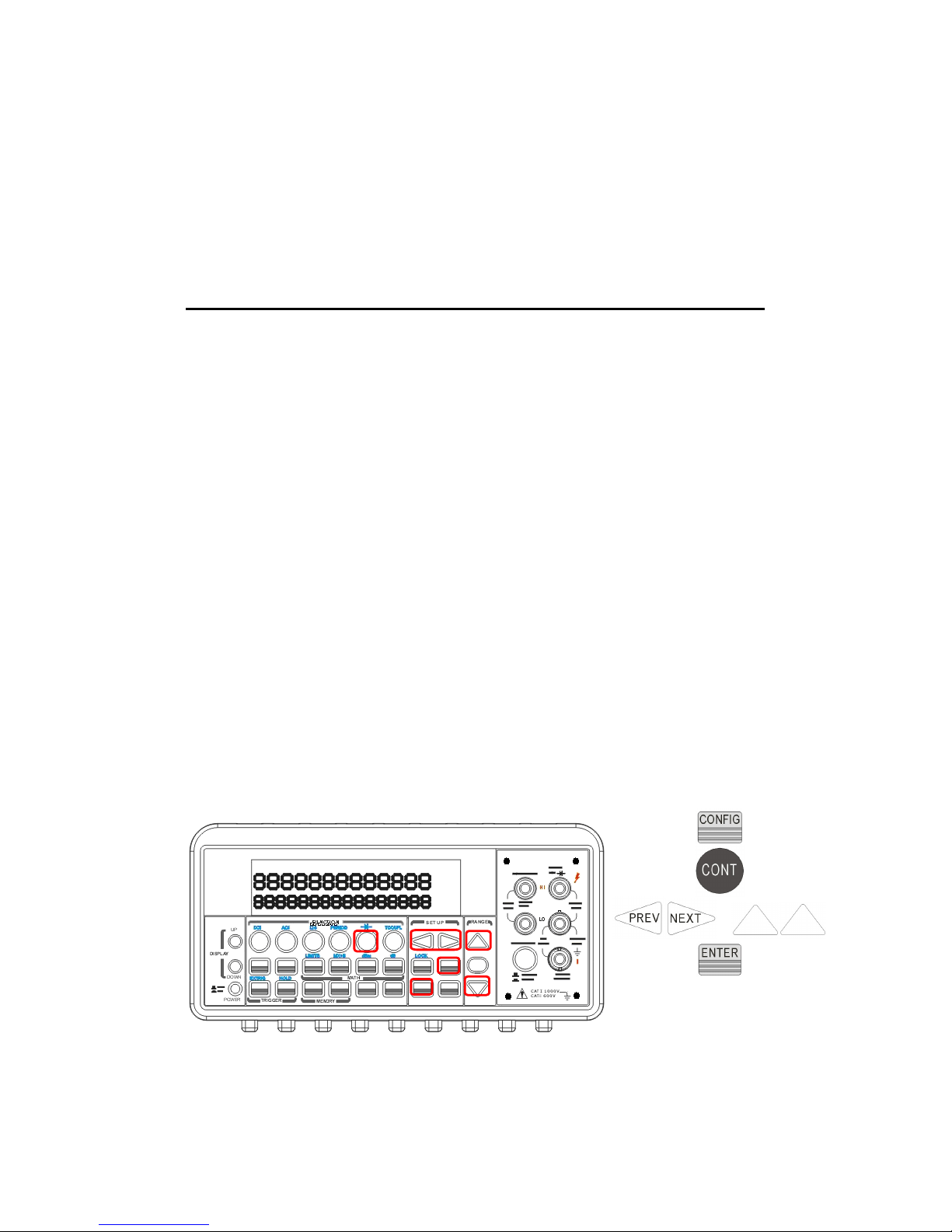
Press CONFIG button and then CONT button. Use ◁ and ▷ buttons to
move through the digits and lower or increase the number to your
desired value using △ and buttons , ▽ then press ENTER button to set
the value. The locations of these buttons are shown with red rectangle
frames in Figure 4-5.
Figure 4-5
61
+
Page 62

4.1.6 Range (Manual & Auto)
Definition
When making measurements except CONT, DIODE and Temperature,
you can let the machine choose ranges for you, or you can select the
appropriate ranges manually by yourself. The difference between auto-
range and manual-range is the settling time. Auto-range is a
convenient way for you, but manual-range can usually speed up the
process.
If the input signal is beyond allowed range, an “OVLD” message will be
shown on the display. The thresholds of maximum/minimum readings
for each range are 120 % of the range for maximum and 10% of the
range for minimum.
Default
The default is auto-range. The user selected range is stored in volatile
memory and the default will be restored when the meter is power-off.
Please refer to Table 2-1 on page 24 for the factory default range.
How to set the auto / manual range:
You can set the auto / manual range either through the front panel
operation or through the remote interface operation.
Front Panel Operation
First choose a measurement function on the front panel, then press
“AUTO” button to select auto-range feature. Or use △ and ▽ buttons
to manually select a range. If selected range is not shown on the
bottom of the display, press round PREV or NEXT buttons until the
range information appears. The locations of these buttons are shown
with a red rectangle frame in Figure 4-6.
62
Page 63
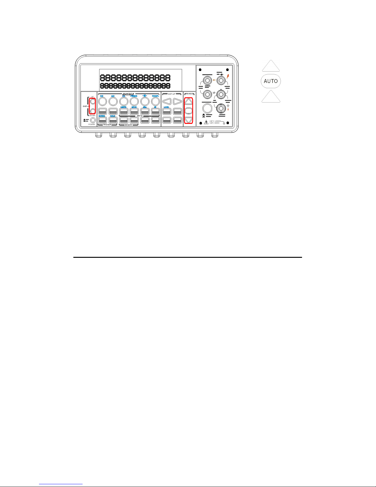
Figure 4-6
Remote Interface Operation
Use the following commands from your PC terminal to set the range:
CONFigure:<function> <range>,<resolution>
MEASure:<function>? <range>,<resolution>
SENSe:<function>:RANGe <range>
SENSe:<function>:RANGe:AUTO {OFF|ON}
4.1.7 Rate (Integration Time)
Definition
Integration time is the period of time the analog-to-digital (A/D)
converter takes to sample the input signal. The integration time
feature allows you to optimize either the speed or the resolution, as
well as the noise rejection and the accuracy of the measurement. The
unit of the integration time is in PLC (power line cycles). One PLC for
60 Hz is 16.67 ms, and for 50 Hz is 20 ms.
There are 4 different integration times in ATM3500A for you to select
from: 0.02, 0.1, 1 and 10 PLCs.
Default
For DCV, DCI, and resistance measurement, the default integration
time is 1 PLC. The user selected value is stored in a volatile memory
and the default value will be restored when the meter is power-off.
63
Page 64

How to set the integration time:
You can set the integration time either through the front panel
operation or through the remote interface operation.
Front Panel Operation
Integration time is set indirectly when you select the measurement
resolution. Please refer to chapter 4.1.3 for details about how to set
resolution or the digits. Table 4-1 on page 51 shows the relationship
between the resolution and the integration time.
Remote Interface Operation
Use the following commands on your PC terminal to set the resolution.
CONFigure:< function> <range>, <resolution>
MEASure:< function>? <range>, <resolution>
SENSe:< function>:RESolution <resolution>
Or you can set integration time directly by the following commands.
SENSe:VOLTage:DC:NPLCycles {0.02|0.1|1|10|MINimum|MAXimum}
SENSe:VOLTage:DC:NPLCycles? [MINimum|MAXimum]
SENSe:CURRent:DC:NPLCycles {0.02|0.1|1|10|MINimum|MAXimum}
SENSe:CURRent:DC:NPLCycles? [MINimum|MAXimum]
SENSe:RESistance:NPLCycles {0.02|0.1|1|10|MINimum|MAXimum}
SENSe:RESistance:NPLCycles? [MINimum|MAXimum]
SENSe:FRESistance:NPLCycles {0.02|0.1|1|10|MINimum|MAXimum}
SENSe:FRESistance:NPLCycles? [MINimum|MAXimum]
For frequency and period measurements, aperture time (or gate time)
is analogous to integration time, and you can use the following
commands to set it. Specify 10 ms (4.5 digits), 100 ms (default; 5.5
digits), or 1 second (6.5 digits).
SENSe:FREQuency:APERture {0.01|0.1|1|MINimum|MAXimum}
SENSe:FREQuency:APERture? [MINimum|MAXimum]
SENSe:PERiod:APERture {0.01|0.1|1|MINimum|MAXimum}
64
Page 65
SENSe:PERiod:APERture? [MINimum|MAXimum]
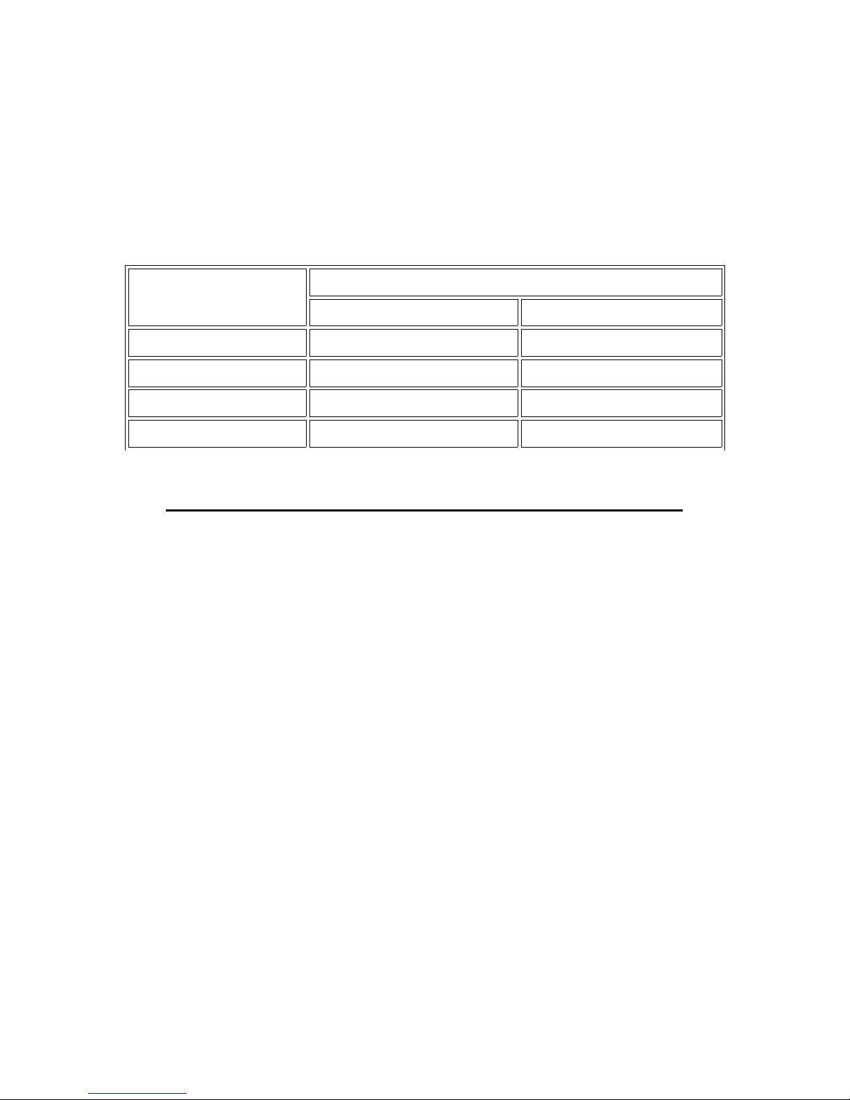
The following table shows the relationship between the integration
time and the measurement resolution.
Integration
Time(PLC)
Resolution
DEFAULT COMPATIBLE
0.02 0.0001 x Full-Scale 0.0001 x Full-Scale
0.1 0.00001 x Full-Scale 0.00001 x Full-Scale
1 0.000001 x Full-Scale 0.000003 x Full-Scale
10 0.0000001 x Full-Scale 0.000001 x Full-Scale
4.1.8
Sensor Selection for Temperature Measurements
The multimeter supports both thermocouple and RTD. You need to
configure the multimeter for the right sensor type, units and
transducer before conducting temperature measurements.
RTD
Definition
If the RTD is used, you have to confirm the RTD settings (incl. sensor,
units and transducer) first throught the front penal operations or the
remote control operation. For the sensor options, they are: PT100,
D100, F100, PT385, PT3916, user-defined RTD, NTCT and SPRTD. For
the unit options, they are: °C, °F and K. For the transducer options,
they are: 2W RTD and 4W RTD.
If you need to change the factors that are used to calculate the
temperature in RTD, choose user-defined RTD in which you are able to
change any factors as you wish. The default factors used are listed in
Table 4-3:
65
Page 66

Table 4-3
Type Alpha Beta Delta R-zero
PT100 0.003850 0.10863 1.49990 100Ω
D100 0.003920 0.10630 1.49710 100Ω
F100 0.003900 0.11000 1.49589 100Ω
PT385 0.003850 0.11100 1.50700 100Ω
PT3916 0.003916 0.11600 1.50594 100Ω
NTCT 0.003850 0.10863 1.49990 100Ω
Here is the temperature equation that is used to determine the RTD
temperature:
When
Ct
°
<
0
:
( )
[ ]
1001
32
0
−+++=
tCtBtAtRR
t
When
CtC
°<<°
6300
:
( )
2
0
1 BtAtRR
t
++=
Where:
+=
100
1
δ
α
A
4
10
−
⋅−=
α δ
B
8
10
−
⋅−=
α β
C
If you are using SPRTD(Standard Platinum RTD), select SPRTD and
specify the seven coefficients under SPRTD submenu.
The ITS (International Temperature Scale) -90 standard provides two
reference equations for Standard Platinum Thermometers covering
temperature range from 18.8033K to 1234.93K. However, one SPRTD
usually cannot cover the entire range, so the temperature range is
broken up into a few subranges. These subranges depend on the
calibration point of temperature scale and are based on the melting or
triple points of various pure substances. For an exact list of the
elements needed and details on RTD calibration, refer to NIST
Technical Note 1265 “Guidelines For Realizing the International
Temperature Scale of 1990”. In each subrange, the calibration
66
Page 67

constants required for that subrange are listed.
Default
The default sensor type, units and transducer in ATM3500A is PT100,
and 4W RTD in order.℃
How to set up RTD
You can set up the RTD configuration either through the front panel
operation or through the remote interface operation.
Front Panel Operation
If you are using RTD, press CONFIG and then TEMP. Use ◁ and ▷ to
locate SENSOR submenu. Press ENTER to go to the submenu. Use ◁
and ▷ to locate your sensor type Press ENTER to select your desired
sensor type. So are the Units and Transducer settings.
Choosing USER takes you to a menu where you can specify factors
used in the calculation equation to obtain the temperature. Use ◁ and
▷
to move through the digits and △ and ▽ to change the numbers to a
desired value. Press ENTER to set the value.
Choosing SPRTD takes you to a menu where you can specify the
seven coefficients that are used to determine the temperature. Use ◁
and ▷ to move through the digits and △ and to change the numbers▽
to a desired value. Press ENTER to set the value.
Remote Interface Operation
Use the following commands to set up the RTD configuration.
SENSe:TEMPerature:RTD:TYPE{PT100|D100|F100|PT385|PT3916|USER|SPRTD|NTCT}
SENSe:UNIT {Cel|Far|K}
SENSe:UNIT?
SENSe:TEMPerature:RTD:RZERo {<value>|MINimum|MAXimum}
SENSe:TEMPerature:RTD:ALPHa {<value>|MINimum|MAXimum}
SENSe:TEMPerature:RTD:BETA {<value>|MINimum|MAXimum}
SENSe:TEMPerature:RTD:DELTa {<value>|MINimum|MAXimum}
67
Page 68

SENSe:TEMPerature:SPRTD:RZERo {<value>|MINimum|MAXimum}
SENSe:TEMPerature:SPRTD:A4 {<value>|MINimum|MAXimum}
SENSe:TEMPerature:SPRTD:B4 {<value>|MINimum|MAXimum}
SENSe:TEMPerature:SPRTD:AX {<value>|MINimum|MAXimum}
SENSe:TEMPerature:SPRTD:BX {<value>|MINimum|MAXimum}
SENSe:TEMPerature:SPRTD:CX {<value>|MINimum|MAXimum}
SENSe:TEMPerature:SPRTD:DX {<value>|MINimum|MAXimum}
SENSe:TEMPerature:TRANsducer FRTD
SENSe:TEMPerature:TRANsducer RTD
Thermocouple
Definition
If you are using the thermocouple function, the selections on the
ATM3500A are: type E, J, K, N, R, S and T. (On the other hand, other
selection “SIMULATED” simulates the reference junction.) To use the
the thermocouple function, you have to adjust something. First of all,
via a thermocouple adaptor, you need to measure a known and
accurate reference temperature (T1) as a criterion. Then the display of
the ATM3500A will show a reference value (T2). At the moment, a
remainder (T3) from (T1 – T2) will be calculated. After that, you just
adjust the default (simulated value 23.0°C) to 23.0°C + (T3). Under
the circumstance, the thermocouple function will be activated
completely.
For Example:
If the criterion value is (T1 =30.0°C), the reference value showing on
the ATM3500A is (T2=24.0°C). You will get a remainder T3 (T1 – T2 =
6.0°C). Then you just configure the default simulated value from
23.0°C to 29.0°C on the ATM3500A.
Note: ATTEN.EU also provides another solution, 10-Channel TC-※
Scanner Card (M3500-opt12), to measure thermocouple. For more
information, please refer to its user’s guide.
How to set up thermocouple
68
Page 69

You can set up the thermocouple configuration either through the front
panel operation or through the remote interface operation.
Front Panel Operation
1.
Configure the thermocouple type and unit. Pressing CONFIG >
SHIFT > TEMP (TCOUPL), and then using PREV and NEXT to select
the type and unit.
2.
Measure a known and accurate reference temperature (T1).
The result showing on the ATM3500A is (T2).
3.
Adjust the simulated value (23.0°C to 23.0°C + T3.)
4.
Configure the Simulated value by pressing CONFIG > SHIFT >
TEMP(TCOUPL) > NEXT > SIMULATED > ENTER, and by
buttons「PREV」 or 「 NEXT」 and & △ ▽ assistance to adjust the value.
Remote Interface Operation
Use the following commands to set up the thermocouple configuration.
SENSe
:UNIT {Cel|Far|K}
SENSe
:UNIT?
SENSe:
TCOuple:TYPE {E|J|K|N|R|S|T}
SENSe:
TCOuple:SIMulated {<value>|MINimum|MAXimum}
4.1.9 Remote Interface Selection
The multimeter supports both GPIB/RS-232 and USB interfaces, but
only one interface can be activated at a time. If you are using GPIB,
you must set the address for the multimeter. You can set the address
to any value from 0 and 31. The address is set to “22” when the
multimeter is shipped from the factory.
Note: The remote interface can be set through the front panel※
69
Page 70

operations only.
How to select a remote interface
Press MENU and then use ◁ and ▷ to select INTERFACE. Then Press
ENTER on your choice of USB or GPIB interface.
How to set address when using GPIB
Press MENU and then use ◁ and ▷ to access INTERFACE. Select GPIB
to set address. Use ◁,
▷,
△
and
▽
to adjust the numbers to the
desired address. Press ENTER to set it.
4.1.10 Input Terminal Switch
Definition
You can select either the front input terminals or the rear input
terminals for your measurements. There are 5 input terminals in the
front panel as well as the rear panel. If the rear terminal is enabled the
REAR annunciator at the upper side will be shown.
Default
The default situation is the front terminals.
How to switch the terminals:
To switch between the front and the rear input terminals, press
“TERMINALS” switch button on the front panel. Please see the
following figure for the location of the switch. The location of the
button and terminals is shown with a red rectangle frame in Figure 4-
7.
70
Page 71
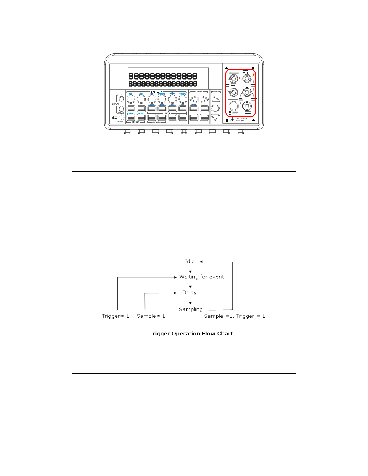
Figure 4-7
4.2 Trigger Operations
In this section we will discuss the triggering system in ATM3500A.
ATM3500A provides a variety of trigger operations. You can select a
trigger mode, a trigger source and different trigger settings for a
specific measurement. The user’s selection is stored in a volatile
memory and the default settings will be restored after power-off.
Figure 4-8 shows the trigger operation in ATM3500A.
Figure 4-8
4.2.1 Trigger Mode
There are three trigger modes in ATM3500A: auto, immediate, and
single triggering. You can specify the trigger mode for your
measurement. The factory default is auto triggering when the meter is
71
Page 72
power-on.
A. Auto Triggering Mode (Front Panel Operation only)
Definition
Auto triggering takes continuous readings at a fastest rate possible for
the present measurement. The rate of taking readings depends on the
current settings. This function is only available through the front panel.
The auto triggering is also the default for trigger mode in ATM3500A.
How to use Auto Trigger
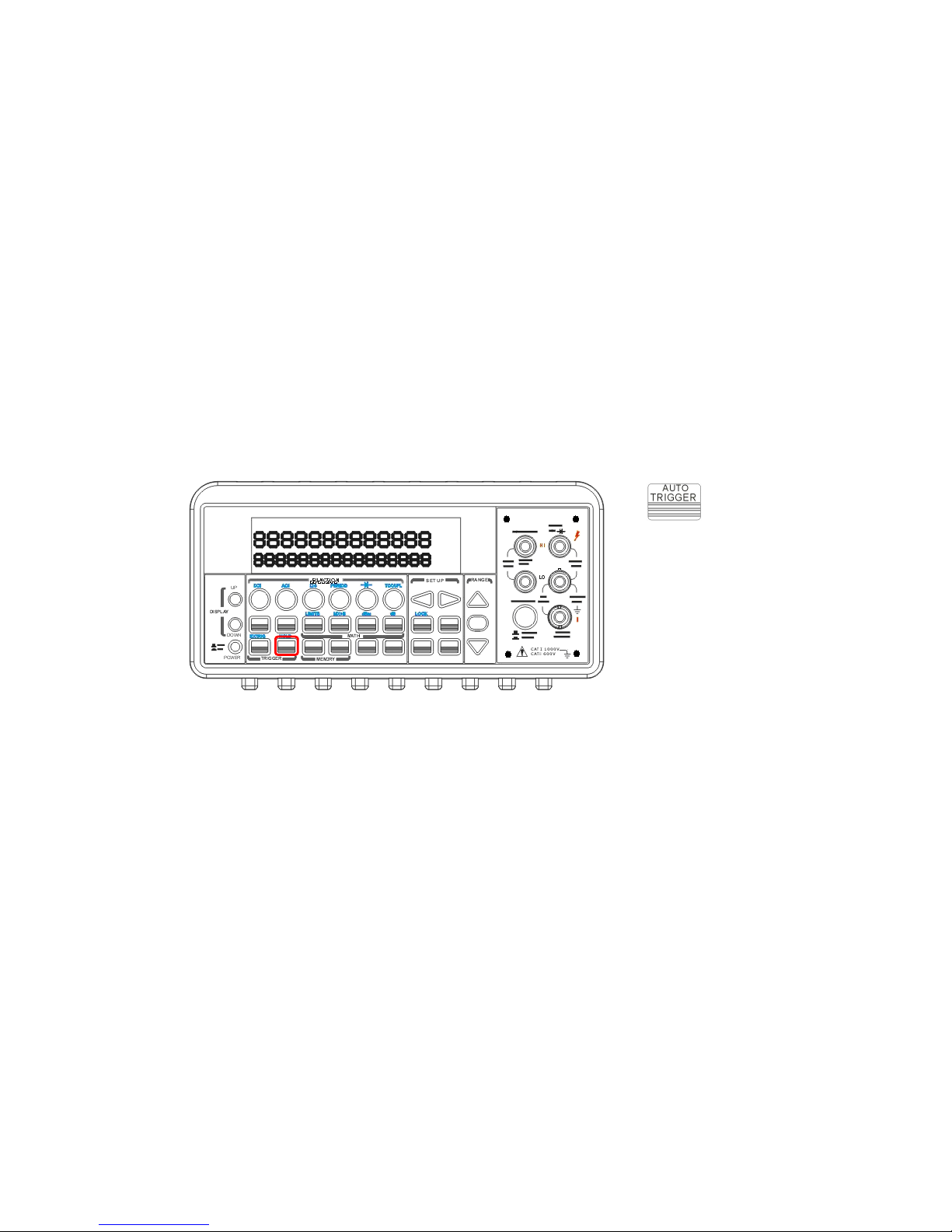
Press ATUO TRIGGER on the front panel to toggle for enabling auto
trigger mode. The location of the button is shown with a red rectangle
frame on Figure 4-9.
Figure 4-9
B. Internal Immediate Trigger Mode (Remote Interface Operation Only)
Definition
The immediate triggering mode is only available through the remote
interface operations and it is the default for the remote interface
operations. When the meter is in immediate trigger mode, a trigger
will be issued immediately as soon as the meter is in “wait for event”
state.
How to use Immediate Trigger
Use the following command in your PC terminal to set the internal
immediate trigger.
72
Page 73
TRIGger:SOURce IMMediate
C. Single Trigger Mode (accessible only through the front
panel)
Definition
Single trigger mode takes one reading (or specified number of
readings) each time when you press SINGLE key. (Please refer to 4.2.3
for setting the number of samples on each trigger.) When the TRIG
annunciator on the display is lit, the meter is ready for next trigger
event. The single trigger mode is only available through the front panel
operations.
How to use Single Trigger
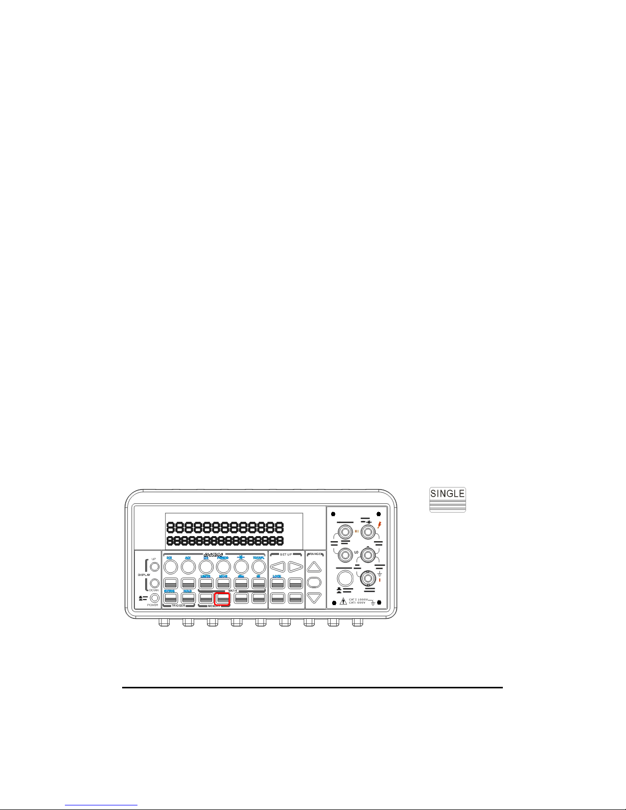
First select the measurement function, and then press SINGLE key on
the front panel to set the trigger mode. The location of the button is
shown with a red rectangle frame in Figure 4-10.
Figure 4-10
4.2.2 Trigger Source
73
Page 74
In ATM3500A, you can specify the trigger source to be one of these
three options: front panel operations, external hardware trigger source
and remote interface operations.
Front Panel Operation
Use the front panel buttons - AUTO TRIGGER for auto triggering and
SINGLE for single triggering.
External Hardware
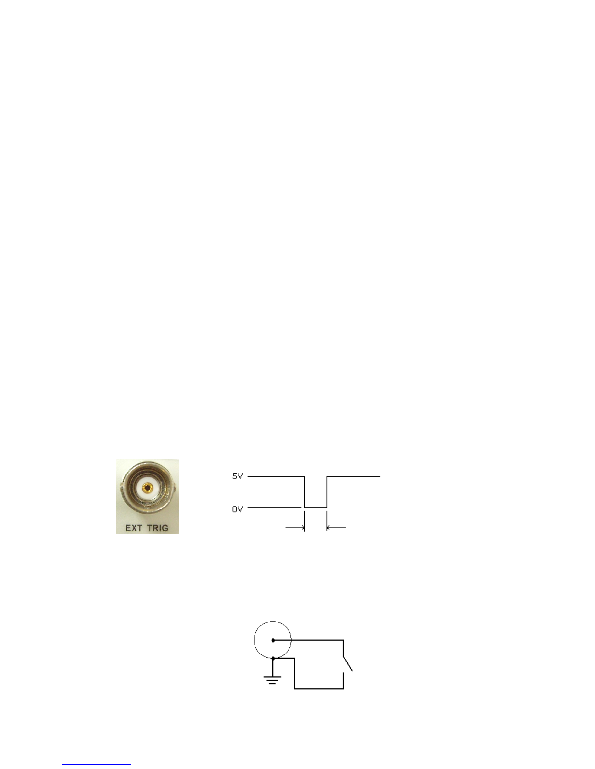
You apply a trigger pulse to the Ext TRIG (BNC) terminal on the rear
panel. External hardware triggering is like using single trigger but the
trigger source is an external hardware. When the multimeter receives
a pulse from the trigger source, it takes one reading, or a specified
number of readings. To set the external hardware trigger, press both
the SHIFT + SINGLE buttons to enable external hardware trigger. The
lit “EXT” annunciator on the display indicates the enabling of the
external hardware trigger.
External Triger Terminal
You can trigger the ATM3500A by using a low-true pulse to the Ext Trig
(external trigger) terminal located on the rear panel. And to use this
terminal via the remote interface, you have to select the external
trigger source by using the TRIGer:SOURce EXTernal command.
Note: You can use a simple switch to generate an external trigger by※
using the Ext Trig input as shown in the following.
74
Input
> 1 μs
Page 75
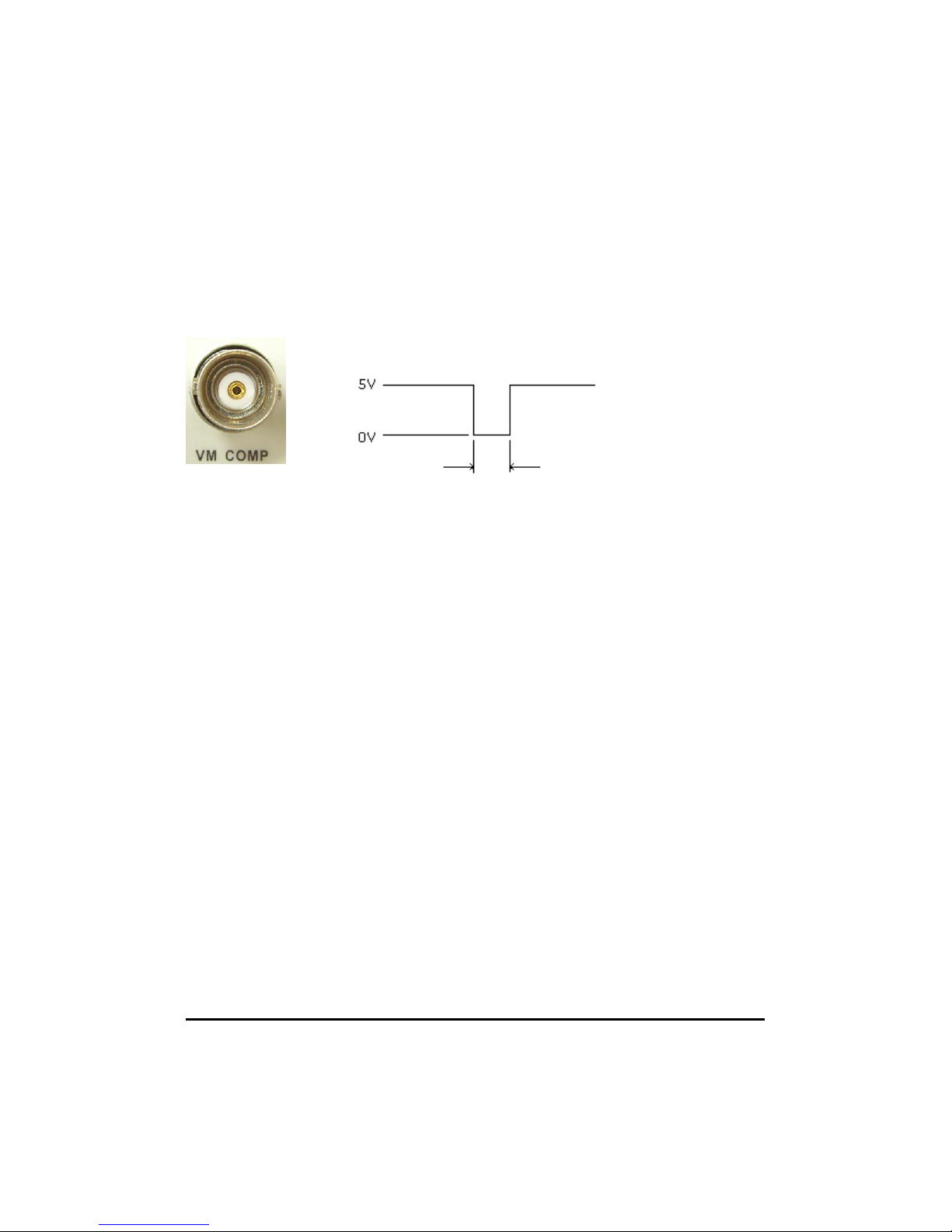
VM COMP (Voltmeter Complete) Terminal
The real panel VM COMP terminal provides a low-true pulse after
finishing each measurement. The VM COMP and external trigger shown
below provides a standard hardware handshake sequence between
measuremen and switching devices.
Remote Interface Operation (By software or internal trigger)
By software trigger: The software trigger is similar to the single
triggering, but instead of using the “SINGLE” button on the front panel,
you send a command from your PC to the multimeter to generate an
event. For using software trigger, use the following command from
your PC terminal to set trigger source:
TRIGger:SOURce BUS
By internal trigger: The internal trigger is the default trigger mode
for the Remote Interface Operation. In the internal trigger mode, a
trigger signal will be issued whenever the multimeter is in the wait-for-
trigger state. To set the internal trigger, use the following command
from your PC terminal:
TRIGger:SOURce IMMediate
4.2.3 Trigger Setting
In ATM3500A, you can specify a variety of trigger settings including
75
Output
Approximately
2 μs
Page 76
the number of samples per trigger, the number of triggers per event,
reading hold, and the trigger delay for your measurements.
A. Number of samples on each trigger
By default, the multimeter takes only one reading on each trigger, but
you can instruct the multimeter to take specific number (up to 50000)
of readings each time it receives a trigger. The user’s input setting is
stored in a volatile memory which will be cleared after the meter has
been turned off and the default value will be restored. You can set the
number of samples on each trigger through front panel or the remote
interface.
Front Panel Operation
Press MENU button and locate “TRIG” submenu by pressing ◁ and ▷
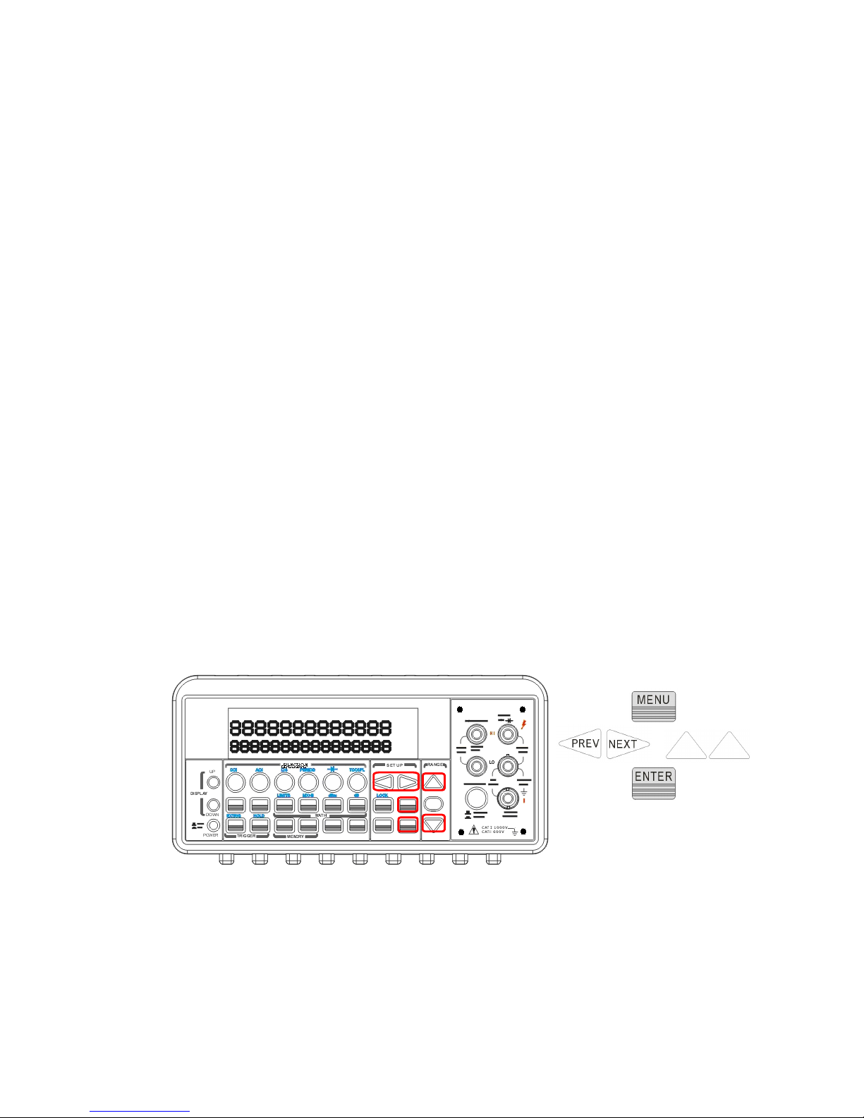
buttons. Press ENTER to choose “TRIG” option. Again locate “N
SAMPLE” submenu using ◁ and ▷ buttons and then press ENTER to
select it. Then set the desired number by pressing △and ▽ buttons to
increase or decrease the number, and using ◁ and ▷ buttons to move
through the digits. The locations of these buttons are shown with red
rectangle frames in Figure 4-11.
Procedures: MENU → TRIG → N SAMPLE →<Number>
Figure 4-11
Remote Interface Operation
Use the following command to set the number of samples from your PC
terminal.
76
+
Page 77
SAMPle:COUNt <value>
B. Number of triggers
Although the meter normally takes one trigger before returning to the
“idle” state, you can manually specify the number of triggers it accepts
before the “idle” state. However, this can only be done through the
remote interface. The following command shows how to set multiple
triggers per returning idle state.
TRIGger:COUNt <value>
C. Reading hold
The reading hold feature is used to hold a stable reading on the
display. When a reading is stable, enabling the reading hold will hold
the stable reading and trigger a beeping sound. Reading hold feature
depends on an adjustable sensitivity band to determine if a reading is
stable. The multimeter considers a reading stable when three
consecutive readings are within the sensitivity band. Chapter 4.4.6 will
explain how to adjust the sensitivity band.
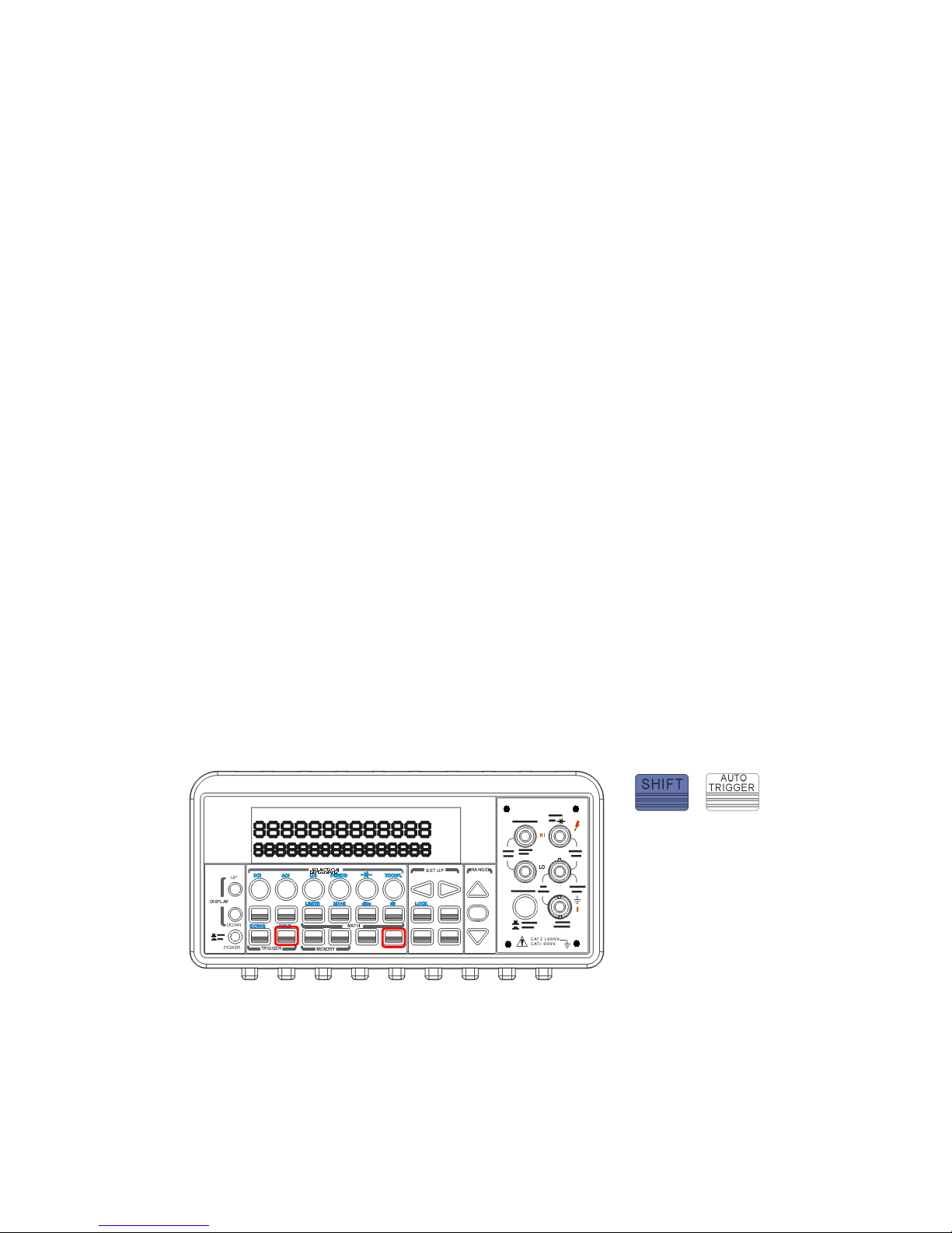
How to use reading hold
This feature is only available from the front panel operations. To enable
reading hold, press both SHIFT and AUTO TRIGGER buttons. To disable
it, simply press AUTO TRIGGER. The locations of the buttons are
shown with red rectangle frames in Figure 4-12.
Figure 4-12
D. Trigger delay
This feature is useful for the user who needs a longer delay time to
77
+
Page 78

wait for the system to be stabilized. The time needed to stabilize a
measurement system is called the “settling time.” The settling time
depends on the measurement range, cable properties and signal
source.
Defaults
The default of the trigger delay is automatic. ATM3500A automatically
selects a delay time for you according to the setting of the
measurement if you do not specify a delay. A list of the default for
each measurement function is shown on Table 4-4. The range for the
delay is from 0 to 3600 seconds. User's selection of delay time is
stored in a volatile memory and the default will be restored when the
meter is power-off.
The internal settings of automatic trigger delay
The delay time for automatic trigger delay is determined by the
selection of measurement function, range, and the setting of
integration time and AC filter speed.
The following table shows the default delay time for each
measurement setting.
Table 4-4
78
Page 79
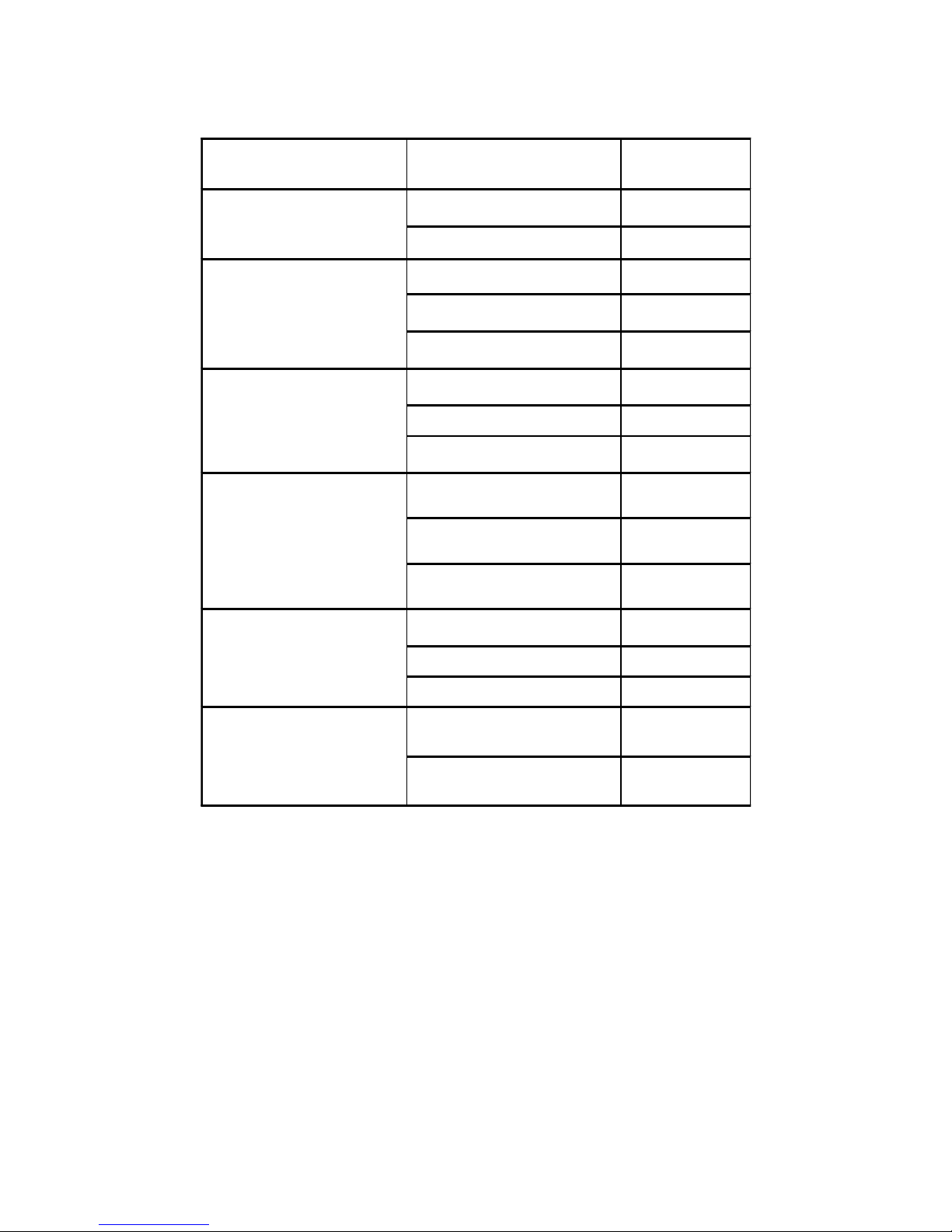
How to specify a delay time
You can set the delay time from either the front panel operations or
the remote interface operations.
Front Panel Operation
To set the delay time, press MENU button and use ◁ and ▷ buttons to
locate “TRIG” option. Press ENTER to select it. Then again find “DELAY”
option using ◁ and ▷ buttons. Press ENTER to select it. Then use ◁
and ▷ buttons to move through the digits and
△
and ▽ buttons to set
the desired delay time (between 0 to 3600 second). The locations of
Measurement Function Setting Trigger Delay
Time
DCV/DCI PLC >= 1 1.5 ms
PLC < 1 1.0 ms
Ω2 and Ω4
(PLC >= 1)
100Ω ~ 100kΩ 1.5 ms
1 MΩ 15 ms
10 MΩ ~ 100 MΩ 100 ms
Ω2 and Ω4
(PLC < 1)
100Ω ~ 100kΩ 1.0 ms
1 MΩ 10 ms
10 MΩ ~ 100 MΩ 100 ms
ACV/ACI
(Remote Interface/
External Trigger/
Single Trigger)
3 Hz 7.0 s
20 Hz 1.0 s
200 Hz 600 ms
ACV/ACI
(Front Panel w/ Auto
Trigger On)
3 Hz 1.5 s
20 Hz 200 ms
200 Hz 100 ms
Frequency/Period Remote Interface /
External
1.0 s
Front Panel w/ Auto
Trigger ON
0 s
79
Page 80
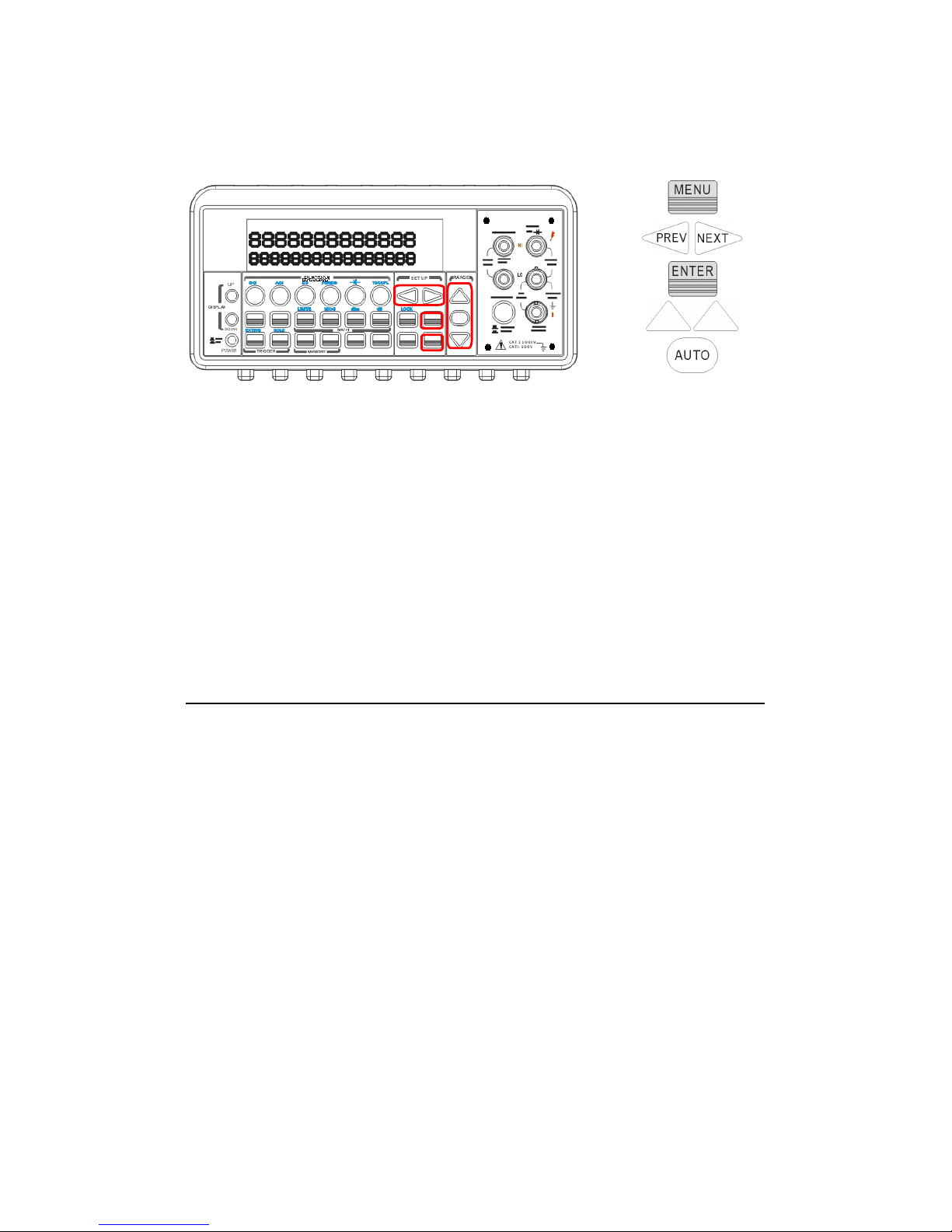
the buttons are shown with red rectangle frames in Figure 4-13.
Figure 4-13
Remote Interface Operation
You can also use the remote interface operations from your PC
terminal to set the trigger delay. To select a delay time, use the
following command or set the trigger delay to be automatic:
TRIGger:DELay {<seconds>|MINimum|MAXimum}
or
TRIGger:DELay:AUTO {OFF|ON}
4.3 Math Operations
This section will introduce the mathematical operations in ATM3500A.
There are eight math operations: RITIO, %, Min/Max, NULL, Limits,
MX+B, dB and dBm testing. They either store data for later use or
perform mathematical operations on the readings. Note that these
math operations are available to all measurement functions except
continuity and diode testing.
※
Note: The “MATH” anunnciator on the display indicates the state of
a mathematical feature, excluding Ratio, and will be lit by enabling
whichever math feature. Also, press the same buttons again for the
enabled math feature will disable the same math feature.
※
Note: Press RATIO button, the “RATIO” anunnciator will be lit on the
display.
80
Page 81
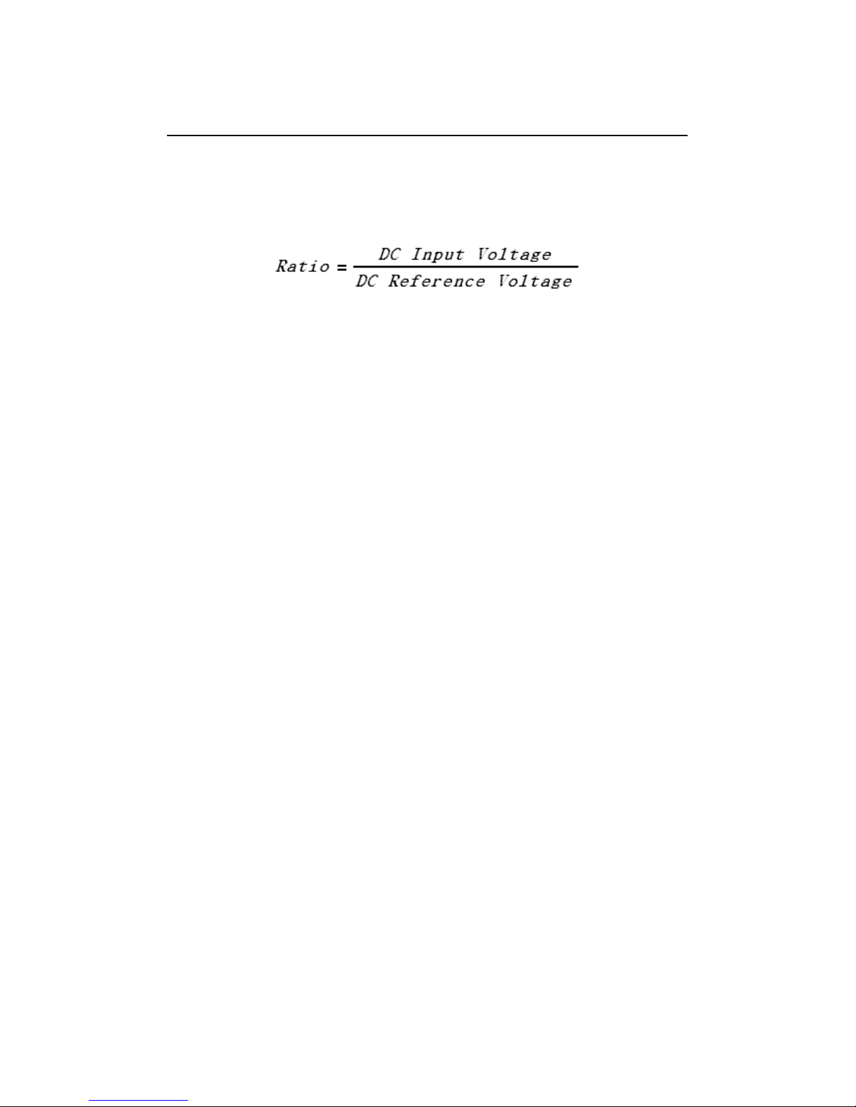
4.3.1 Ratio
This function calculates the ratio of an input DC voltage to a reference
DC voltage according to the following equation:
How to make a ratio measurement
There are two ways to make a ratio measurement: Through the front
panel operation or through the remote interface operation.
Front Panel Operation
Use TERMINALS button to select the front terminals or the rear
terminals. Press CONFIG + RATIO, and then use ◁ and ▷ buttons to
locate “RESOLUTION” option (Refer to 4.1.3) and “FILTER” option
(Refer to 4.1.2.2). Press ENTER to make choices. Then select desired
value for it by pressing ◁, ▷, and button. Press ENTER to choose△ ▽
it. For operating this function, please press RATIO button and observe
the reading on the display as shown as Figure 4-14.
※
Note: To close this function, please press one of the measurement
function buttons.
※
Note: The max. DC input voltage is 1000 V, and the max. DC
reference voltage is 200 V.
81
Page 82
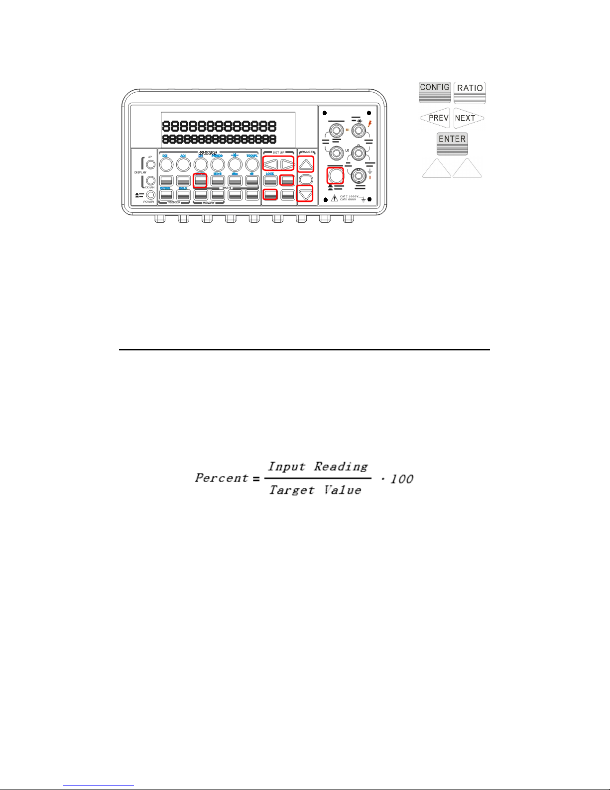
Figure 4-14
Remote Interface Operation
Use the following command to make a RATIO measurement.
CONFigure:VOLTage:DC:RATio {<range>|MIN|MAX|DEF},{<resolution>|MIN|MAX|DEF}
4.3.2 % (Percent)
Definition
This mathematical function calculates the ratio of a measurement
reading to a specified target value as the form of percentage. The
calculation formula is shown below:
The specified target value is store in a volatile memory and will be
cleared after the meter has been turned off or a remote interface
reset.
How to use % (Percent) function
There are two ways to make a percent measurement: Through the
front panel operation or through the remote interface operation.
Front Panel Operation
To specify a target value, you need to configure Percent function by
pressing CONFIG + %, then use ◁ and ▷ to move through the digits
and △ and ▽ buttons to increase or decrease the numbers to a desired
82
Page 83
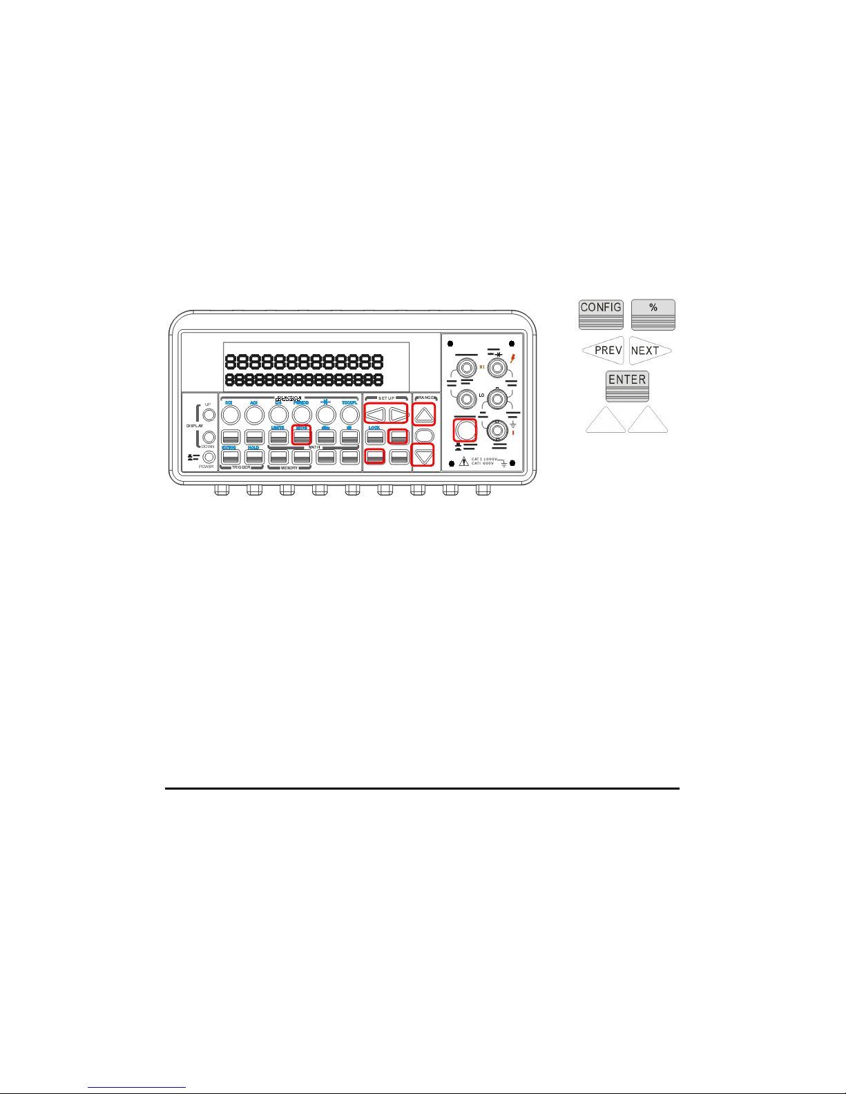
target value. Press ENTER to set the value. Press % to activate this
function. And then observe the calculated percent value on the display
as shown as Figure 4-15.
※
Note: Press % again to disable this function. The “MATH”
annunciator on the display indicates the state of a mathematical
feature.
Figure 4-15
Remote Interface Operation
Use the following commands to enable and configure Percent function:
CALCulate:FUNCtion PERCent
CALCulate:STATe {OFF|ON}
CALCulate:STATe?
CALCulate:PERCent:TARGet {<value>|MINimum|MAXimum}
CALCulate:PERCent:TARGet? [MINimum|MAXimum]
4.3.3 Min/Max
Definition
When the Min/Max function is enabled, the multimeter takes in a series
of readings from the measurements, stores the minimum and
maximum readings in the memory, and then calculates the average
value of all readings. The number of readings taken since Min/Max
operation is enabled is recorded as well. These data are stored in a
83
Page 84
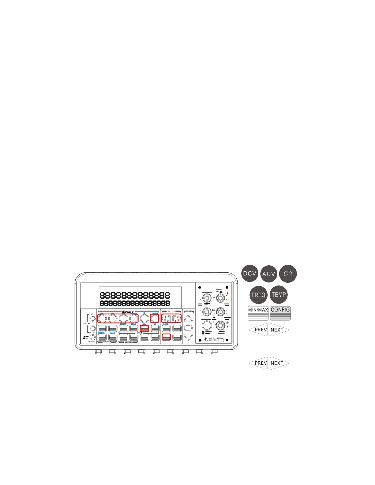
volatile memory and will be cleared when the meter is turned off, or
when the MIN/MAX is turned on, or after a remote interface reset. The
meter beeps every time when it captures a new minimum or
maximum.
How to use Min/Max
You can use the Min/Max feature either through the front panel
operation or the remote interface operation.
Front Panel Operation
First of all, you select the measurement function you wish to use, and
then press MIN/MAX button to enable the Min/Max function. To read
the min/max value, the average value or the readings count, you can
press CONFIG button and then MIN/MAX button. Use ◁ and ▷ buttons
to switch between those values. The locations of the buttons are
shown with red rectangle frames in Figure 4-16.
※
Note: Press MIN/MAX again to disable this feature. The “MATH”
anunnciator on the display indicates the state of a mathematical
feature.
Figure 4-16
Remote Interface Operation
The following commands show you how to use the Min/Max operation
from your PC terminal.
84
Page 85

CALCulate:FUNCtion AVERage
CALCulate:STATe {OFF|ON}
CALCulate:STATe?
CALCulate:AVERage:MINimum?
CALCulate:AVERage:MAXimum?
CALCulate:AVERage:AVERage?
CALCulate:AVERage:COUNt?
4.3.4 Null
Definition
When null function is enabled, the displayed measurement reading is
the difference between the measured input signal reading and the
stored null (also called relative) value. The null (relative) value is
stored in a volatile memory and the value will be cleared when the
multimeter is power-off. Moreover, you can specify or alter a null value.
The null feature is available for all functions, except continuity, diode.
When you select the null feature for a measurement, it is visible only
for this measurement.
How to use null (relative) measurement
You can activate null feature from either the front panel operation or
the remote interface operation.
The Front Panel Operation
The null measurements can be used with any function except
continuity and diode. To store the null test lead resistance, short the
two test leads together and then press NULL button. The new reading
taken will replace the old value, if any, in the null register. Then,
connect the two test leads to the input source. The value with null
offset will show on the display. In addition, the null offset value can be
adjusted manually by pressing CONFIG then NULL. Use ◁ and
▷
buttons to move through the digits and use △ and
▽
buttons to
increase or decrease the numbers to a desired value. Press ENTER to
set the value. The locations of the buttons are shown with red
85
Page 86
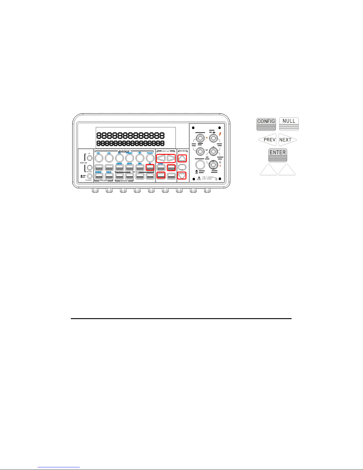
rectangle frames in Figure 4-17.
※
Note: Press NULL again to disable this feature. The “MATH”
anunnciator on the display indicates the state of a mathematical
feature.
Figure 4-17
The Remote Interface Operation
You can use the following commands on your PC terminal to make a
null measurement.
CALCulate:FUNCtion NULL
CALCulate:STATe {OFF|ON}
CALCulate:STATe?
CALCulate:NULL:OFFSet {<value>|MAXimum|MINimum
}
4.3.5 Limits Test
The limits testing operation allows you to adjust a maximal and a
minimal limit values. The multimeter beeps and an “HI” or “LO”
message will be shown when the reading exceeds the upper or lower
limit respectively. You can specify the limit values and the values are
stored in a volatile memory. The default values for both upper and
lower limits are “0”. This function is available to all except continuity
and diode measurements.
※
Note: You can also use this HI/LO measurement as a Pass/Fail
86
Page 87

application through the USB interface’s Pin 2 and Pin3. But the USB
interface has to be turned off by pressing MENU >
▷ > INTERFACE >
ENTER > ▷ > INTERFACE > ENTER > USB > ENTER > DISABLE > ENTER
.
How to set the limits
You can set the limits or make a limit testing either through the front
panel or the remote interface operation.
Front Panel Operation
To set the limits, you need to configure the LIMITS math function by
pressing CONFIG + SHIFT + RATIO, and then use ◁ and
▷
to locate
either lower limit (MIN) or upper limit (MAX). Press ENTER to select
the limit you wish to set. Then use ◁ and
▷
to move through the digits
and
△
and
▽
to increase or decrease the numbers to a desired value.
Press ENTER to set the value. The locations of the buttons are shown
with red rectangle frames in Figure 4-18.
Figure 4-18
How to make a limit testing
The locations of the buttons are shown with red rectangle frames in
Figure 4-19.
Select a measurement function for purpose except continuity and
diode.
87
Page 88
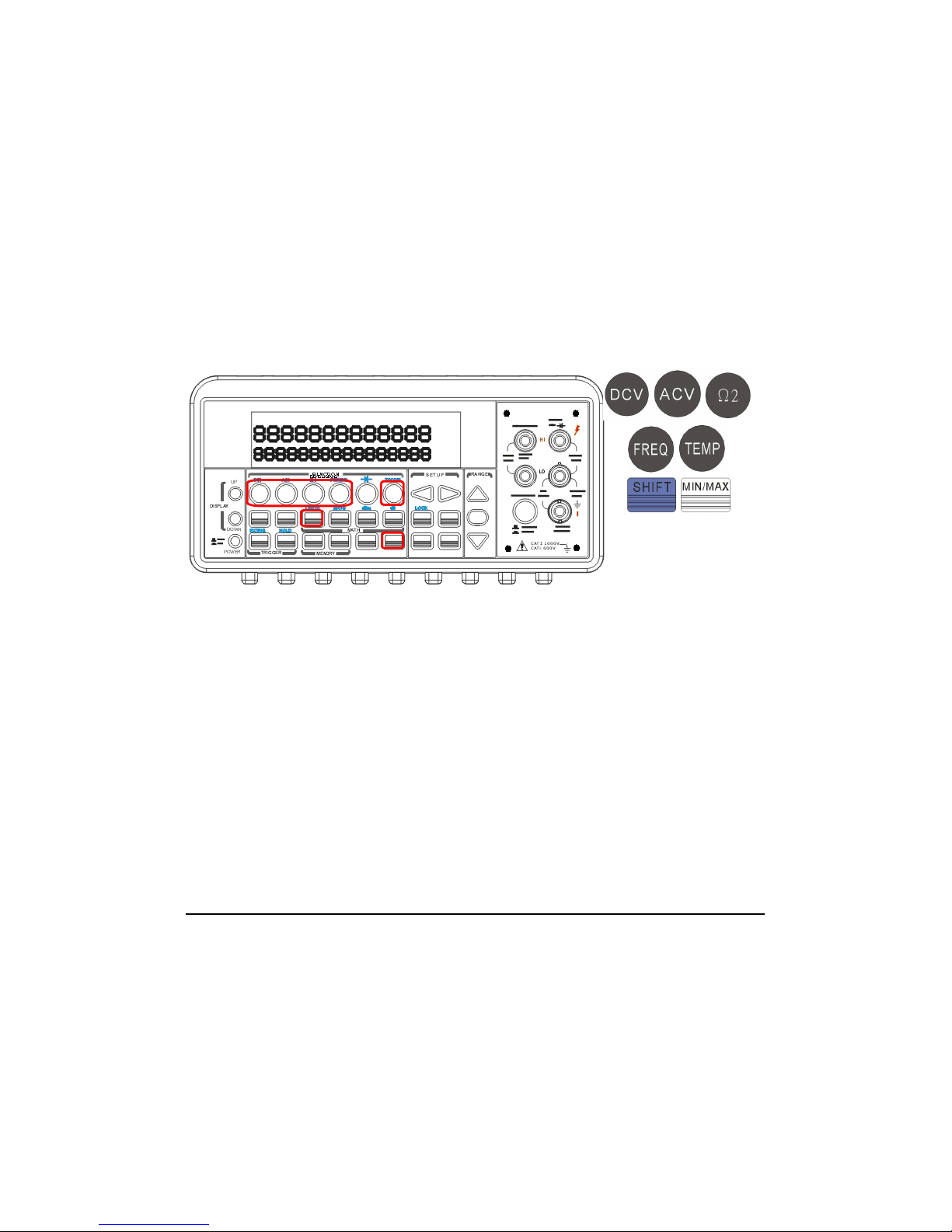
Enable the limit operation by pressing SHIFT + RATIO buttons.
After enabling the limit function, you can set the limit value as
mentioned above.
Observe the displayed reading.
※
Note: Press SHIFT+RATIO again to disable this feature. The “MATH”
anunnciator on the display indicates the state of a mathematical
feature.
Figure 4-19
Remote Interface Operation
Use the following commands to enable the limits function or to set the
limits:
CALCulate:FUNCtion LIMit
CALCulate:STATe {OFF|ON}
CALCulate:STATe?
CALCulate:LIMit:LOWer {<value>|MINimum|MAXimum}
CALCulate:LIMit:UPPer {<value>|MINimum|MAXimum}
4.3.6 MX+B
Definition
This mathematical function multiplies a measurement reading (X) by a
specified scale factor (M) and add an offset (B) automatically. The
answer (Y) will then be shown on the display according to the following
equation.
88
Page 89

Y=MX+B
This is especially useful when you need to do slope calculations on a
series of measurements.
The values of the “M” and “B” can be changed through the
configuration of this function and they are stored in a volatile memory
and will be cleared after the meter has been turned off or a remote
interface reset.
You can either use front panel or remote interface to perform this
function and set these two constant.
How to use MX+B function
You can use MX+B function from the front panel operation or the
remote interface operation.
We provide two application examples for your reference. The first one
is that if you have to use scanner card to obtain the current value (For
more specification information, refer to the scanner card user’s
guide.). Second, if the input current source you want to measure
exceeds the current specification, 3A, of the ATM3500A.
Then the DCV/ACV and MX+B functions would be helpful. The current
value is calculated through the equation as follows. “I=V/R”.
Where: I = Current being determined
V = Voltage measured by the DMM
R = Shunt resistance value
As to the MX+B setting, “M” stands for “1/R”, “X” stands for “voltage
measured by the DMM” and “B” stands for “Offset, 0”.
Application1.
(via the scanner card and the PT-TOOL software for the multipoint
measurement, but it has some limitations when using it.):
1. Switch the terminal to the rear control.
2.
Build in the necessary current shunt on the R1/R2 location
89
Page 90

(available measurement for CH1/CH6 only). Or externally
connect current shunts in parallel connection to the required
Channel(s) among CH1 ~ CH10 and current source(s). (The
section 4.4.5 has the diagram explanation of the scanner card.)
3.
Insert the scanner card into the DMM carefully.
4.
Connect the output A’s leads to the rear terminal INPUT HI
and LO.
5. Execute the PT-TOOL.
6.
Choose DCI function to activate the MX+B function. You need
to input the “R” value and the Offset “I” value if you know.
7.
Press YES to start the measurement.
※
Note: We can’t accept the input source exceeding (ACV: 125V/
DCV: 110V) or the components on the scanner card might be burned
out. It’s better to use the front terminal to test sources first.
Application 2.
(via the front panel operation for the single current measurement.):
Case: Mr. Obama wants to measure a source, 10A, through a 0.1Ω
current shunt and a ATM3500A DMM. However, the DMM’s tolerance
just can stand the maximum input current, 3A. What should he do?
Please obey the following procedures and illustrations as a big current
measurement solution.
1. Switch the terminal to the front control.
2.
Externally connect a current shunt “0.1Ω” in parallel
connection to the INPUT HI & LO and a current source 10A.
3.
Press CONFIG > SHIFT + % to set the MX+B. You need to
input the current shunt value “M = 1/0.1= 10Ω” and the Offset
90
Page 91
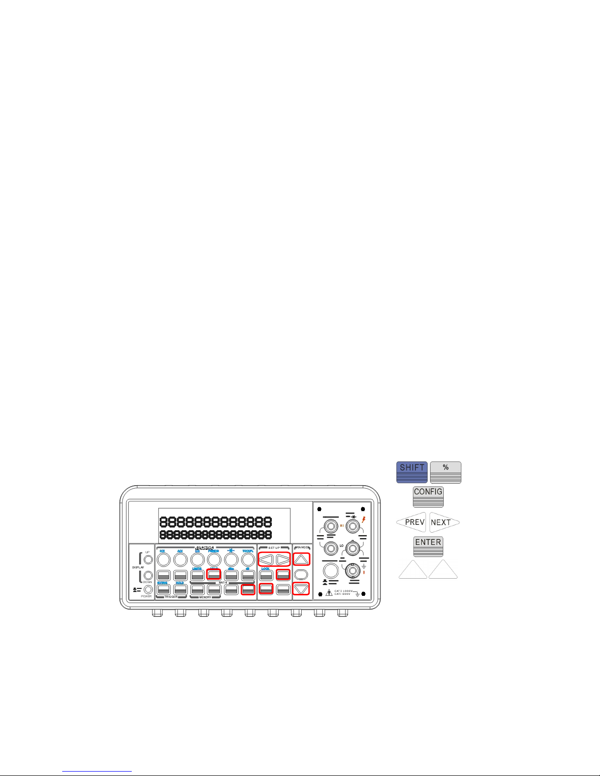
“B, ex: 0” value.
4. Press ENTER to confirm the settings.
5.
Press DCV function.
6.
Activate the MX+B math function by pressing SHIFT + %
buttons.
7.
The DMM’s display will show a value +9.969XXXE+00. (This
measurement also can be used with the PT-TOOL software.
Please refer to the 5 ~ 7 procedures of the Application 1.)
※
Note: If the input source exceeds the specification ACV:750V /
DCV:1000V, the display will show OVLD.
Front Panel Operation
To set the values of M and B, you need to configure this math function
by pressing CONFIG and SHIFT + %. Use ◁ and ▷ to switch between
M and B. Press ENTER on your selection. Then use ◁ and ▷ to move
through the digits and use △ and ▽ to increase or decrease the
number to a desired value. Press ENTER to set the value. You need to
set the values of M and B first. Then Select a measurement function
and press SHIFT + % to activate MX+B function as shown as Figure
4-20.
Figure 4-20
Remote Interface Operation
Use the following commands to enable and configure MX+B function:
91
Page 92

CALCulate:FUNCtion MXB
CALCulate:STATe {OFF|ON}
CALCulate:STATe?
CALCulate:MXB:MMFactor {<value>|MINimum|MAXimum}
CALCulate:MXB:MMFactor? [MINimum|MAXimum]
CALCulate:MXB:MBFactor {<value>|MINimum|MAXimum}
CALCulate:MXB:MBFactor? [MINimum|MAXimum]
4.3.7 dB/dBm
A. dB
Definition
The dB feature takes a DC or AC voltage measurement and displays it
in decibel unit in correspondence to a relative reference value. The
calculation of dB is listed below:
or
dB = (Input signal in dBm) – (relative value in dBm)
※
NOTE: The
in
V
is the input signal and the
ref
V
is the relative
reference.
The dB measurement is applied to DC and AC voltage only. The relative
value is adjustable and is stored in a volatile memory. The range for
the relative value is between 0 dBm and 200 dBm.
How to set the relative value
You can either manually select a number for the relative reference or
let the multimeter take the first reading (0 dB).
Front Panel Operation
Press CONFIG+ SHIFT+ NULL buttons, and then use ◁ and
▷
to move
through the digits and △ and ▽ buttons to increase or decrease the
92
)log(20
Vref
V
dB
in
×=
Page 93
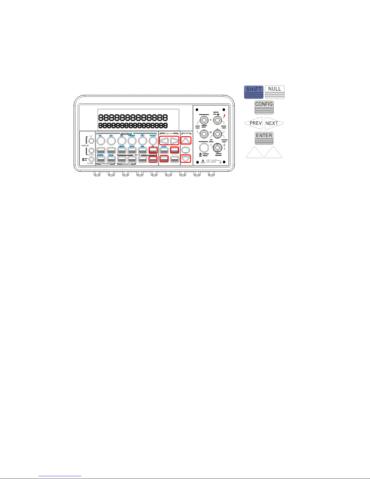
numbers to your desired value. Press ENTER to set the value. The
locations of the buttons are shown with red rectangle frames in Figure
4-21.
Figure 4-21
How to make a dB measurement
Select the measurement function by pressing one of DCV and ACV
buttons.
Enable the dB operation by pressing SHIFT + NULL buttons.
After enabling the dB operation, you can set or alter the dB relative
value as mentioned above.
Observe the displayed reading.
Figure 4-22 shows the locations of these buttons with red rectangle
frames
.
※
Note: Press SHIFT+NULL again to disable this feature. The “MATH”
anunnciator on the display indicates the state of a mathematical
feature.
93
Page 94
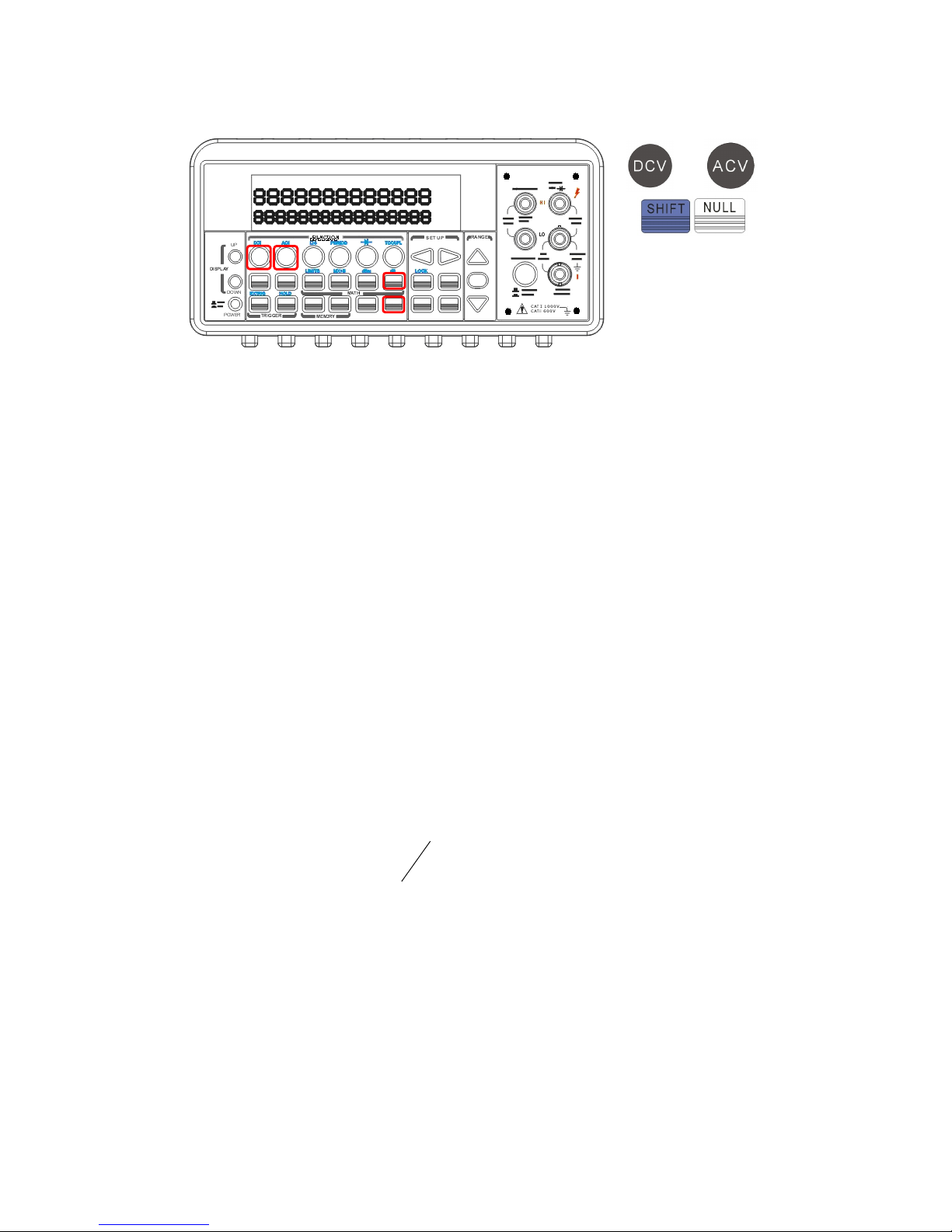
Figure 4-22
Remote Interface Operation
Use the following commands from your PC terminal to make the dB
measurement:
CALCulate:FUNCtion DB
CALCulate:STATe {OFF|ON}
CALCulate:STATe?
CALCulate:DB:REFerence {<value>|MINimum|MAXimum}
B. dBm
Definition
With dBm selected, a voltage measurement is displayed as the level of
power, relative to 1 milliwatt, dissipated through a reference
resistance. The reference resistance is adjustable in ATM3500A. The
calculation of dBm is defined as below:
mW
Z
V
dB
ref
in
m
1/log10
2
×=
Note:※
in
V
is the input signal voltage.
ref
Z
is the reference resistance.
Note:※ Change of reference resistance will not affect the stored
relative reference value.
The Zref is adjustable with a range from 50Ω to 8000 Ω. The
default value is 600 Ω.
94
or
Page 95
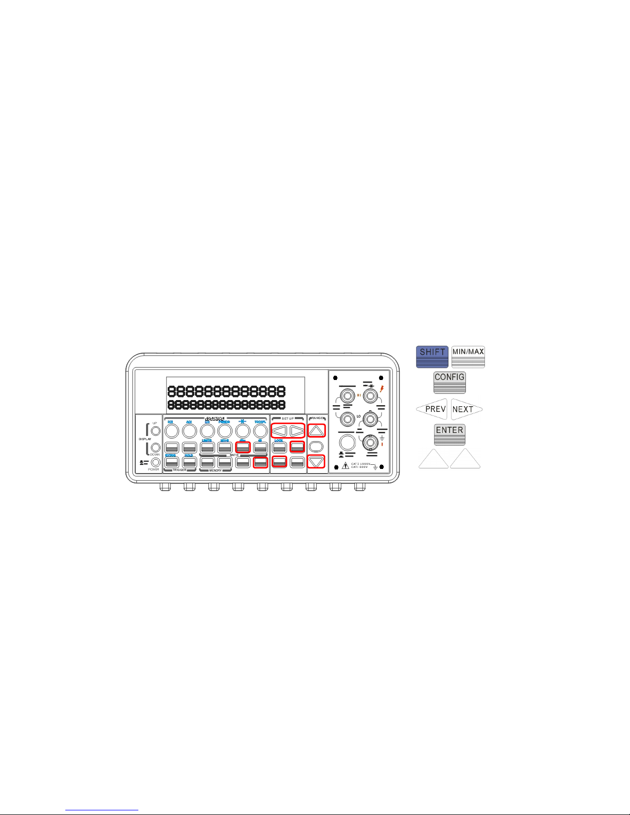
The selected reference value by you is stored in a volatile memory
and will be cleared after the multimeter has been power-off.
This feature is available for DCV and ACV only.
How to set the reference resistance
You can set the reference resistance either through the front panel
operation or the remote interface operation.
Front Panel Operation
Press CONFIG + SHIFT + MIN/MAX, then use ◁ and ▷ to move
through the digits and
△
and ▽ to increase or decrease the numbers
to a desired value. Press ENTER to set the value. The locations of the
buttons are shown with red rectangle frames in Figure 4-23.
Figure 4-23
How to make a dBm measurement
Select a measurement function by pressing DCV or ACV button. The
dBm feature is only available for DCV and ACV only.
To enable dBm, press SHIFT + MIN/MAX buttons.
After enabling the dBm operation, you can select the reference
resistance as mentioned above. The default for the reference
resistance is 600 Ω.
95
Page 96
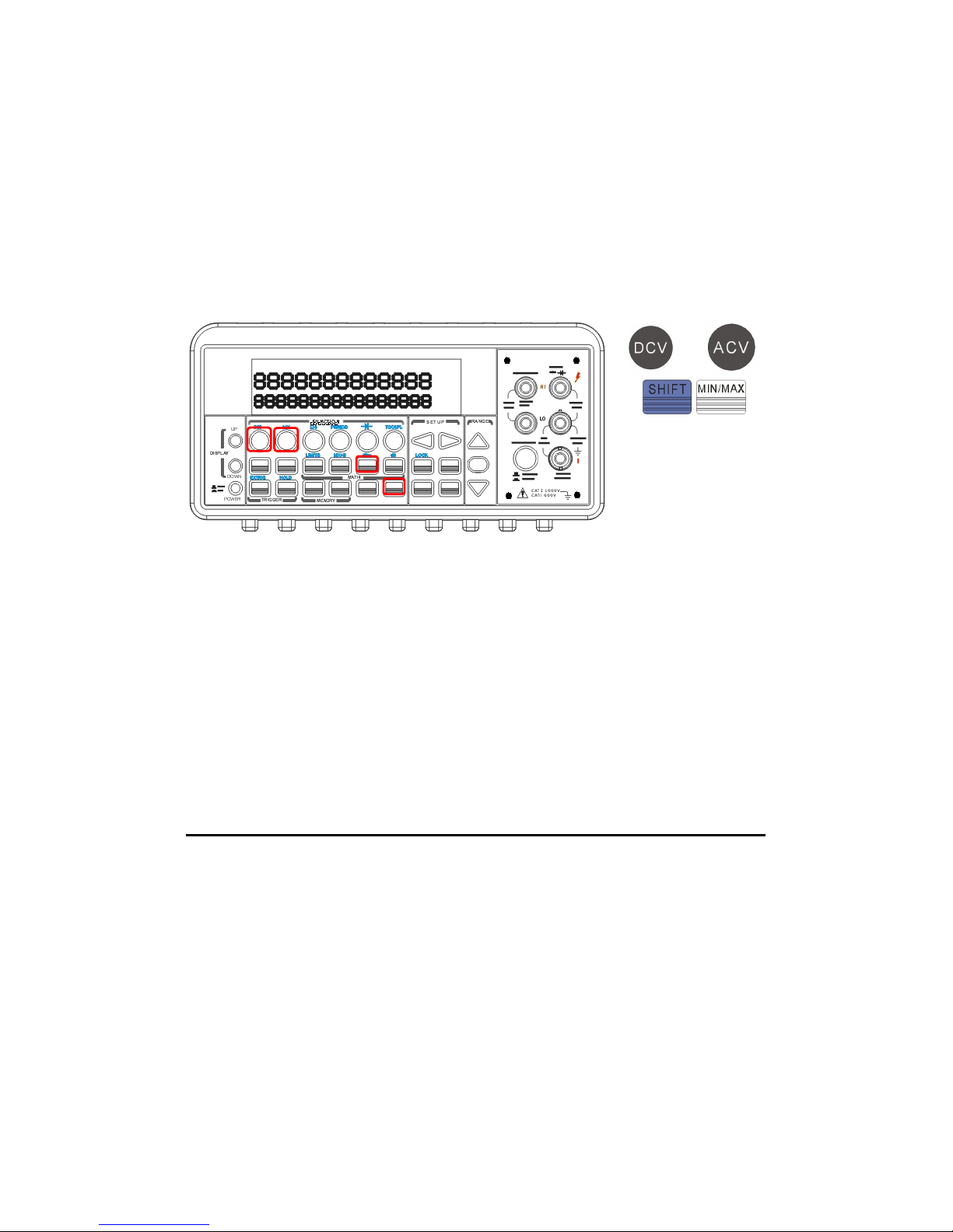
The locations of the buttons are shown with red rectangle frames in
Figure 4-24.
※
Note: Press SHIFT+MIN/MAX again to disable this feature. The
“MATH” anunnciator on the display indicates the state of a
mathematical feature.
Figure 4-24
Remote Interface Operation
Use the following commands to enable dBm feature or to set the
reference resistance:
CALCulate:FUNCtion DBM
CALCulate:STATe {OFF|ON}
CALCulate:STATe?
CALCulate:DBM:REFerence {<value>|MINimum|MAXimum}
96
or
Page 97
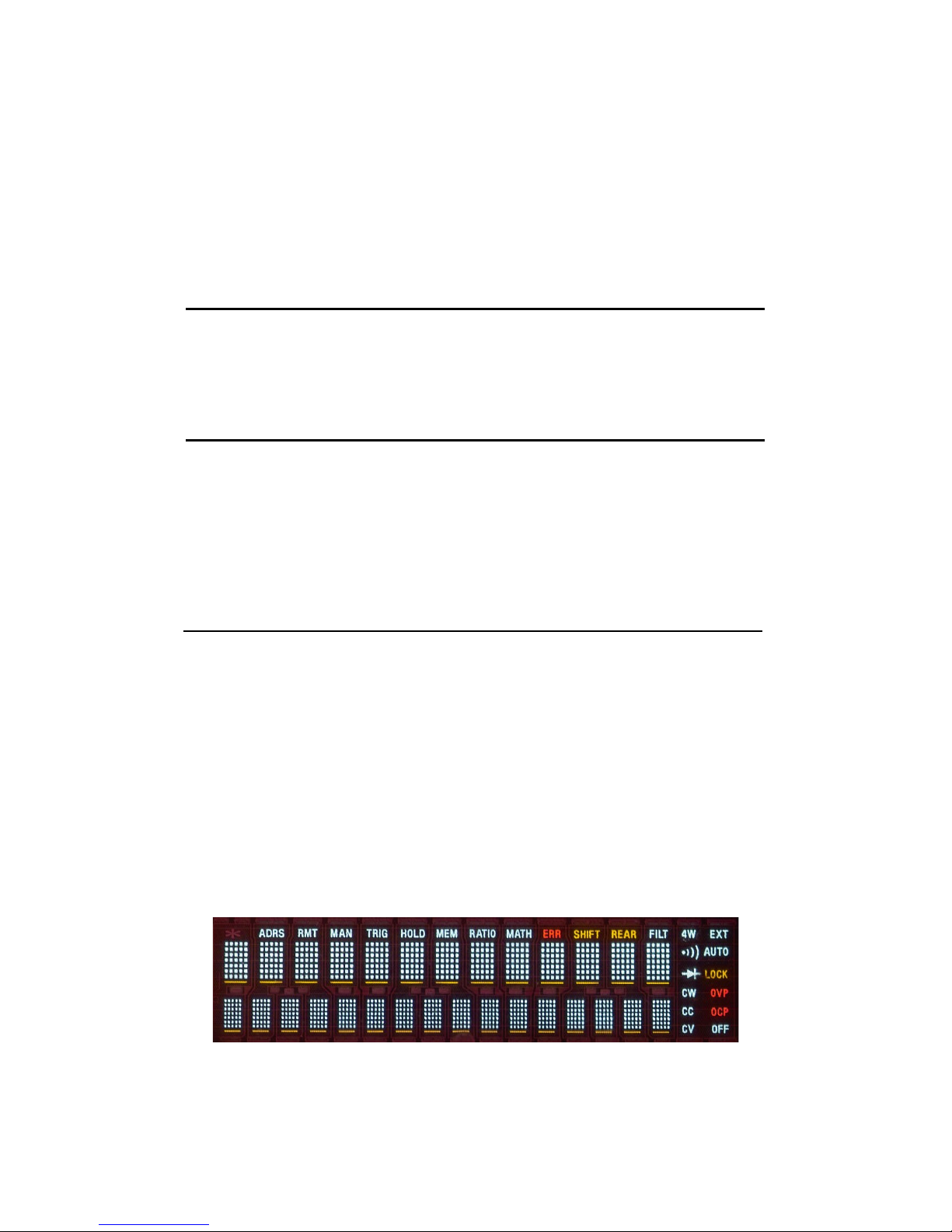
4.4 Other System Related Operations
Each system related operation performs a task that is not
measurement related but plays an important role in making your
measurements.
4.4.1 Display
ATM3500A has a 5x7 dot matrix, dual-display with three-color (White,
Red and Yellow
)
annunciators for a better view. A maximum 13
characters are allowed for upper row dot-matrix display and a
maximum 16 characters are allowed for lower row dot-matrix display
as shown on Figure 4-25.
You
have an option to turn off the display
for a faster measurement without waiting for display, or when the
measurement is done through the remote interface operations on you
PC terminal.
Figure 4-25
97
Page 98

When the display is turned off, an “OFF” will be lit at the lower right
corner of the display screen. This doesn't mean the display is POWER-
OFF, but only that the measurement readings will not be sent to the
display. This option will accelerate the measurement process because
there is no I/O delay. But turning off the display will not affect the
messages displayed from the RECALL, MENU and CONFIG operations.
You can send a message through the remote interface from your PC
terminal to the lower row display and will substitute the original
display.
Default
The display default is “ON”. The “On/Off” selected by you is stored in a
volatile memory and the default “ON” will be restored when the meter
is power-off.
How to control the display
You can control the display through the front panel operation or
through the remote interface operation. The remote interface operation
has higher priority over the front panel operation.
Front Panel Operation
Use the following steps to control the display: Press MENU button then
use ◁ and ▷ buttons to locate “SYSTEM” submenu. Press ENTER to
select it, and then again use ◁ and ▷ buttons to locate “DISPLAY”
submenu. Press ENTER to select it, and then find ON or OFF by using
◁
and ▷ buttons. Press ENTER on your selection. The locations of the
buttons are shown with red rectangle frames in Figure 4-26.
Procedures: MENU → SYSTEM → DISPLAY → {ON|OFF}
98
Page 99
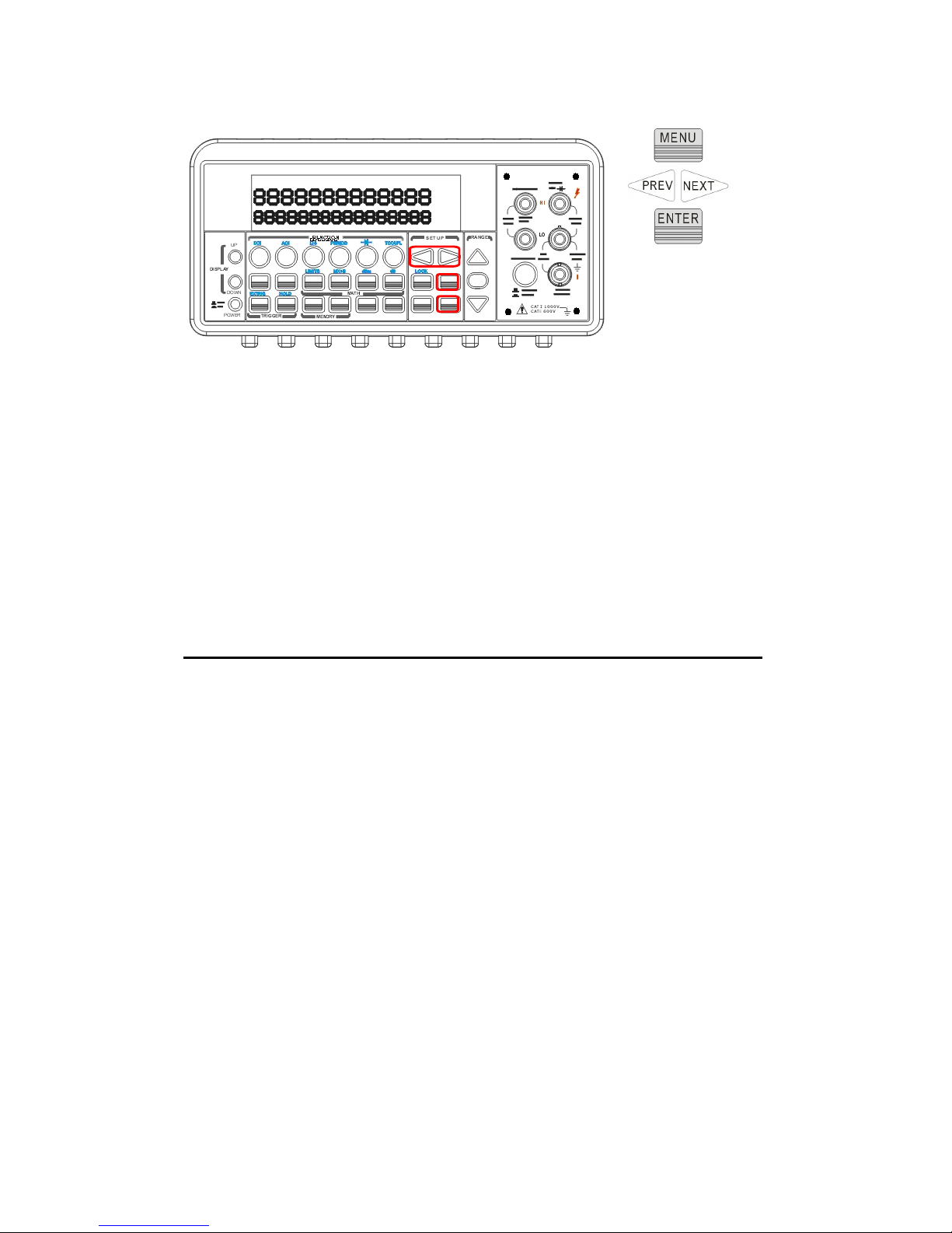
Figure 4-26
Remote Interface Operation
The following commands show how to control the display as well as
how to send a message to the display:
DISPlay {OFF|ON}
(
turns off or turns on the display
)
DISPlay:TEXT <quoted string> (displays the string you type in)
DISPlay:TEXT:CLEar (clears the message displayed)
4.4.2 Beeper
ATM3500A multimeter beeps when some certain conditions are met or
when an error occurs. But there may be time you want to disable the
beeper for some operations. Although you can turn off the beeper, the
click sound you hear when a button is pressed will not be disabled. The
beeper state is stored in a volatile memory and the default will be
restored when the meter has been turned off or after a remote
interface reset.
By disabling the beeper you will not hear the meter beeps
when
:
a new minimum or maximum is found in Min/Max operation.
a stable reading is detected and held
.
the test voltage is within the limits in diode testing.
99
Page 100
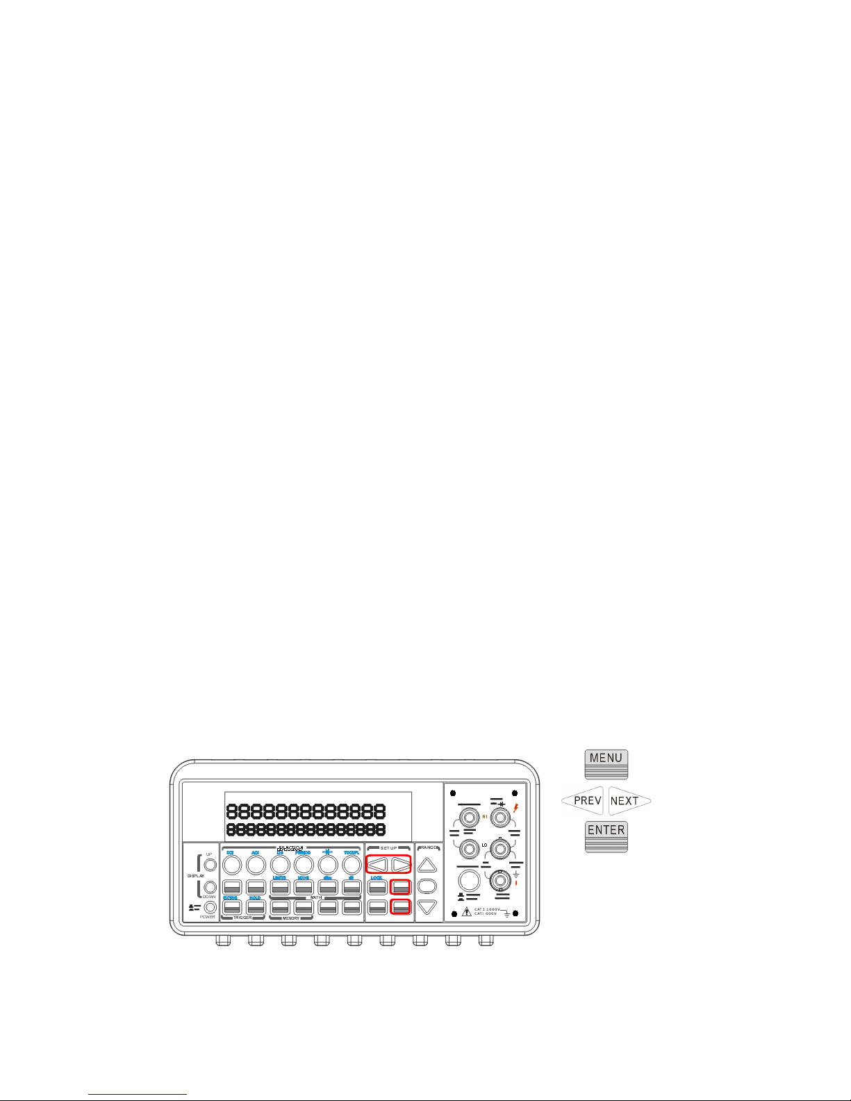
the source signal fails the limit testing.
After the beeper is disabled, the meter still emits a tone when:
an error occurs.
any button on the front panel is pressed.
the threshold value is exceeded in continuity testing.
Default
The beeper is enabled when it is shipped from the factory.
How to control the beeper
You can control the beeper from either the front panel operation or the
remote interface operation.
Front Panel Operation
Follow the procedure below to disable or enable the beeper: Press
MENU button then use ◁ and ▷ buttons to find SYSTEM menu. Press
ENTER to choose it, and then again use ◁ and ▷ buttons to find BEEP
menu. Press ENTER to choose it, and then find ON or OFF by using ◁
and ▷ buttons. Press ENTER on your selection. The locations of the
buttons are shown with red rectangle frames in Figure 4-27.
Procedures: MENU → SYSTEM → BEEP→ {ON|OFF}
Figure 4-27
100
 Loading...