

Page 1
EN 06/2019
EN
ATTACK
WOOD&PELLET
Instruction for use
www.attack.sk
Page 2

Page 3

CONTENTS
CONTENTS ...................................................................................................................................................................... 2
1GENERAL INFORMATION .................................................................................................................................. 4
INTRODUCTION ........................................................................................................................................... 4
1.1
SAFETY ............................................................................................................................................................ 4
1.2
BOILER OPERATION .................................................................................................................................. 4
1.3
SAFETY ITEMS FOR WORK WITH THE BOILER .................................................................................... 5
1.4
BOILER MODIFICATION ............................................................................................................................. 5
1.5
BASIC DESCRIPTION OF THE BOILER ................................................................................................. 5
1.6
FUEL ................................................................................................................................................................. 6
1.7
WOOD .................................................................................................................................................... 6
1.7.1
PELLETS ................................................................................................................................................. 7
1.7.2
ALTERNATIVE FUELS.......................................................................................................................... 7
1.7.3
2BOILER ASSEMBLY AND INSTALLATION ...................................................................................................... 8
HANDLING THE BOILER ............................................................................................................................. 8
2.1
GENERAL CONDITIONS OF INSTALLATION ........................................................................................ 8
2.2
BINDING NORMS FOR PROJECTING AND INSTALLATION OF THE BOILERS ................... 9
2.2.1
PLACING THE BOILER .............................................................................................................................. 10
2.3
BOILER CONNECTION TO THE HEATING SYSTEM .......................................................................... 11
2.4
PROTECTION AGAINST CORROSION ......................................................................................... 12
2.4.1
CHIMNEY ............................................................................................................................................ 13
2.4.2
FLUE GAS CONNECTION OF THE BOILER ................................................................................. 13
2.4.3
CONNECTION TO THE ELECTRICITY MAINS ............................................................................ 13
2.4.4
CONNECTION OF THE EXTERNAL PELLET TANK ................................................................... 14
2.4.5
LEFT DOOR VERSION ...................................................................................................................... 14
2.4.6
CHOICE AND WAY OF CONNECTION OF THE CONTROL AND SAFETY ELEMENTS .... 14
2.4.7
CONNECTION TO THE ACCUMULATION TANKS ................................................................... 17
2.4.8
3WARRANTY CONDITIONS .............................................................................................................................. 19
4TECHNICAL PARAMETERS ............................................................................................................................. 20
DIMENSIONS OF THE BOILER ATTACK WOOD&PELLET 25 ......................................................... 21
4.1
5REGULATION OF THE BOILER AND THE HEATING SYSTEM ................................................................ 22
IN GENERAL ................................................................................................................................................ 22
5.1
EMERGENCY ACTIONS ............................................................................................................................ 22
5.2
PREPARATION FOR THE OPERATION, FILLING THE INTEGRATED PELLET TANK ................. 23
5.3
6BOILER START-UP ............................................................................................................................................. 23
7DESCRIPTION OF THE SAFETY DEVICES .................................................................................................... 23
BASIC DESCRIPTION ................................................................................................................................ 23
7.1
TEST MODE................................................................................................................................................. 26
7.2
BOILER’S OPERATION.............................................................................................................................. 30
7.3
OPERATION WITH WOOD ............................................................................................................. 32
7.3.1
DESCRIPTION OF THE MAIN CONTROL MODES .................................................................... 51
7.3.2
COMBINED OPERATION MODE .................................................................................................. 57
7.3.3
8DISPLAYING INFORMATION ......................................................................................................................... 59
2
Page 4

9SETTING THE PARAMETERS .......................................................................................................................... 62
10SPECIAL SETTINGS ........................................................................................................................................... 65
11INTERNET CONNECTION ................................................................................................................................ 67
12TIMER SETTINGS ............................................................................................................................................... 69
13SOFTWARE UPDATES ...................................................................................................................................... 70
14FACTORY SETTINGS AND FILES LOADING ............................................................................................... 72
15FAULTS OF THE BOILER ATTACK WOOD & PELLET .............................................................................. 73
16BOILER MAINTENANCE .................................................................................................................................. 73
17BOILER CLEANING ............................................................................................................................................ 74
18ASSEMBLY AND DISSASSEMBLY OF THE REFRACTORY ITEMS ......................................................... 75
19TABLE OF RELATION OF THE RESISTANCE AND THE TEMPERATURE OF THE SENSOR PT 1000 ............. 76
20ELECTRICAL CONNECTION SCHEME .......................................................................................................... 77
21OVLÁDANIE AUTOMATICKÉHO KOTLA .................................................................................................... 80
22ACCESSORIES .................................................................................................................................................... 82
23INSTRUCTIONS FOR DISPOSAL OF THE APPLIANCE AFTER ITS LIFETIME ENDS .......................... 83
DISPOSAL OF PACKAGING .................................................................................................................... 83
23.1
24SERVICE PARAMETERS SETTINGS................................................................................................................ 83
25THE ORIGINAL ES DECLARATION OF CONFORMITY ............................................................................. 93
3
Page 5
1 GENERAL INFORMATION
INTRODUCTION
1.1
Dear customer,
thank you for your trust and purchase of our product – the combined boiler ATTACK WOOD&PELLET.
The boiler construction is based on the newest knowledge of the biomass combustion and meets all
current test criteria and EU directives.
Please read this manual carefully and keep it near the boiler for reference. This manual contains important information, including information for correct, safe and economical boiler operation.
Constant improvement of our products may mean small differences in the pictures and content and
we reserve right to make technical changes of products without previous announcement.
SAFETY
1.2
The following three warning signs are used in this manual for illustration of the threat of danger
and for important safety notifications:
DANGER! There is imminent danger and serious threat to health or property. Follow the
given instructions!
WARNING! Potentionally dangerous situation that could cause serious threat to health
or property if advised actions are not taken. Take care!
CAUTION! Take care and follow the advised actions.
BOILER OPERATION
1.3
CAUTION! No unauthorized personel to enter the boiler room, there may be serious risk
to health or property. Operator of the system must ensure that no unauthorized person,
particularly children, enter the boiler room.
4
Page 6
SAFETY ITEMS FOR WORK WITH THE BOILER
1.4
To work on the boiler please use correct personal protective equipment including heat resistant
gloves, suitable cloths and safety shoes.
BOILER MODIFICATION
1.5
CAUTION It is forbidden to make any changes to the construction of the boiler or
disable any safety and protection devices fitted to the boiler.
BASIC DESCRIPTION OF THE BOILER
1.6
The ATTACK WOOD&PELLET is a modern environmentally friendly boiler that saves environment
by efficient burning of biomass. The user gets the advantage of low operating costs from wood
combustion as well as the convenience of the heating system comparable with gas boilers when
burning the pellets. The boiler is intended for heating of dwelling houses, cottages, factories,
industrial units, etc.
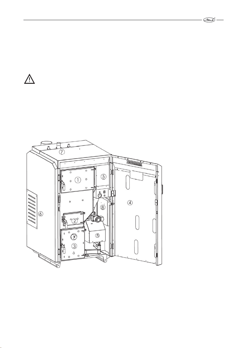
Basic description of the boiler
Pic. 1
1 –wood feeding chamber door, 2 –middle door for ignition and cleaning, 3 –combustion chamber door with a sight-hole, 4 – main door, 5 – burner for pellet combustion, 6 – secondary and
primary air inlet for gasification, 7 – boiler flow connection, 8 – boiler control electronics.
5
Page 7

MJ/kg
The boiler consists of the wood feeding and combustion chamber, pellet combustion chamber,
pellet burner, integrated pellet tank and heat exchanger. The boiler can be operated in either
wood mode or pellet mode, but not at the same time. The boiler is designed with reference to
the user comfort, i.e. to save time for heat-up, fuel cutting, cleaning and total time spent by the
boiler. The basic part of the boiler is a water cooled body, welded from boiler steel plate of 3–
6 mm to ensure long life time. The feeding chamber for gasification is equipped with a dry coat.
By elimination and moving the condensation point from the boiler body to the surface of the dry
coat is the boiler´s life extended. The dry coat can be easily exchanged, if it comes to its damage.
Turbulators in the tubular exchanger improve heat transfer into the heating water and ensure
automatic exchanger cleaning to maintain high efficiency during the operation and to extend
the boiler life. The boiler body is insulated with mineral wool. The covering is powder coated.
FUEL
1.7
WOOD
1.7.1
In the boiler ATTACK WOOD&PELLET it is possible to burn soft and hard chopped fuel wood with
the heat value 15–17 MJ/kg. Particularly suitable is beech, oak, fir, spruce, pine, poplar, alder,
willow, birch, ash, wych-hazel, locust, always within the humidity range of 12–20 %. Recommended diameter of the wood logs is in the range of 80–150 mm. The maximum length of wood
logs is 580 mm and it must not be exceeded, otherwise they would get stuck in the feeding
chamber.
The heat value of the particular wood types:
Units
Wood Kcal/kg
Spruce 3 900 16,25 4,5
Pine 3 800 15,80 4,4
Birch 3 750 15,50 4,3
Oak 3 600 15,10 4,2
Beech 3 450 14,40 4,0
CAUTION! Wrong humidity or size of the wood may cause increase or decrease of output, low or high flue gas temperature, excessive condensation, flame loss during the gasification process or uncontrollable combustion.
Recommended storing and drying the wood:
Hard wood: 2 years in dry environment
Soft wood: 1 year in dry environment
When storing (drying) the wood, it has to be protected against rain. To dry the wood more efficiently, stack to keep as large air gaps as possible. The wood will season faster with airflow over
the wood. If possible, store the wood for at least 1 day at a warm place (e.g. boiler room) before
loading it into the boiler (as it is warm, the efficiency of burning is increased).
kWh/kg
6
Page 8

PELLETS
1.7.2
The pressed wood pellets wihout any additional materials can be burned in the boiler. Parameters of the pellets should be following:
Approved pellet specification:
Measured weight: 600 – 750 kg/m3
Heat value: 4,7 – 5,0 kWh/kg
Size/diameter: 6 mm
Size/length: Caution! Max. 35 mm
Humidity – max.: 12 %
Ash content: 0,5–1 %
Content of crumble (dust:) max. 3 %
Ash melting temperature: min. 1 100°C
Norms : DIN 51 731 – HP 5, DIN Plus, or EN 14961-2 – A1
ALTERNATIVE FUELS
1.7.3
It is possible to use the wood briquettes made from pressed wood sawdust without any additional adhesives or bidning materials.The briquettes must be always mixed in the appropriate
ratio to the wood (dependent on the size and shape of the briquettes) and must not stuck in the
refractory nozzle for wood gasification.
CAUTION! Use of unsuitable fuel types causes higher cleaning requirements and accumulation of an agressive sediments and condensation that may lead to reduced functionality, damage to the boiler and invalidate the warranty. Burning the wrong fuels may
cause incorrect and uncontrollable combustion.
7
Page 9
2 BOILER ASSEMBLY AND INSTALLATION
HANDLING THE BOILER
2.1
The boiler is delivered on a pallet. Handle it always on the pallet and put it down from the pallet
only at the point of installation. This can be done by a manipulation trolley or a crane and lifting
eye that is not included into the delivery (recommended specification: lifting screw with an eye
M20 ISO 3266, or M20 DIN 580). The lifting eye can be screwed into the chassis welded on the
upper cover of the boiler to hang the boiler. Carrying capacity of the hanging eye M20 is 1 200
kg, weight of the boiler is approximately 860 kg. Remove the upper boiler cover before hanging
the boiler on the hanging eye.
Handling the boiler with the hanging screw with eye
Pic. 2
GENERAL CONDITIONS OF INSTALLATION
2.2
The boiler can only be installed by a properly certified installer with valid certification to install
and assemble the heating appliances. Before installation, there must be a project made following to the valid prescriptions. Before installation of the boiler, the worker must check accordance
of the data on the data plate with the data given in the project and documentation of the boiler.
Connection of the boiler must be done in conformity to the valid directives, norms, ordinances
and this instruction manual.
CAUTION! The producer takes no responsibility for damage caused by incorrect
connection or incorrect operation.
8
Page 10

BINDING NORMS FOR PROJECTING AND INSTALLATION OF THE
2.2.1
BOILERS
Installation of the boiler must be done in conformity with the following norms:
STN EN 303-5 Heating boilers for solid fuels
STN 73 42 10 Manufacture of chimneys
STN EN 60 335.1 +A11 Safety of the electrical appliances for household
STN EN 12828+A1 Central heating, projecting and installation
STN 06 08 30 Safety devices for central heating and D.H.W. preparation
STN 07 74 01 Water and steam for thermal energetic devices with opera-
tion pressure of steam up to 8 MPa
STN 332000 4-46 Electrical installations of buildings – part 4: Ensuring safety
STN 33 2000–1:2009-04 Electrical installations of buildings – part 3: Definition of the
basic characteristics
STN EN ISO 11202 Acoustics. Noise generated by machines and devices. Defini-
tion of the emissions levels of the acoustic pressure at
a workplace and other precisely defined places by using the
approximative corrections in environment. (ISO 11202: 2010)
STN EN ISO 12100 Safety of machines. General principles of construction of ma-
chines. Consideration and elimination of the risk (ISO 12100:
2010)
STN EN ISO 14120:2016 Safety of machines. Protection covers. General requirements
for design and construction of fixed and movable covers.
STN ISO 27574-2 Acoustics. Statistical methods for definition and verification
of the determined values of the noise emission of machines
and devices. Part 4: Methods for series of machines.
STN ISO 1819 Devices for fluent cargo transport. Safety prescriptions. Gen-
eral clauses.
STN EN ISO 15614-1 Requirements for quality of the fusion welding of metal ma-
terials
STN EN 287-1 Welding of reserved technical devices
STN 07 0240 Low pressure boilers, technical prescriptions
STN 07 0245 Warm water boiler with the output up to 50 kW. Technical
requirements, testing
STN 07 7401 Water and steam for heat energy devices with the steam op-
erating overpressure up to 8 MPa.
STN 73 4210 Manufacturing the chimneys and flue ways and connection
of devices
9
Page 11

PLACING THE BOILER
2.3
The boiler is intended for installation and operation in an area conforming to (AA5/AB5) under
the STN 33 2000-3.
The boiler room must fulfill the above mentioned and the following requirements:
• There can be no potentionally explosive environment in the boiler room, as the boiler is not
suitable for usage in such environments.
• The temperature in the boiler room must not drop below freezing
• Boiler itself does not provide any lighting. The user must ensure sufficient source of light,
according to the local norms and directives.
• If the boiler is going to be installed above an altitude of 1 800 m, the installation has to be
consulted with the manufacturer
• There must be an opening of at least 200 cm2 in the boiler room for sufficient ventilation and
supply of the required amount of the air for combustion. The external environment should
not influence the functionality of the opening (rain, snow, wind).
When installing the boiler, it is necessary to keep a safe distance of its surface from flammable materials, according to the degree of flammability:
• from materials of flammability B, C1 a C2 200 mm
• from materials of flammability C3 400 mm
• from materials with the grade of flammability not approved under the STN 73 0853 400 mm
Examples of classification of the building materials by their degree of flammability:
• degree of flammability A inflammable (bricks, blocks, ceramic tiles, mortar, parging)
• degree of flammability B partly flammable (heraklith, lignos, board from basalt felt, novodur)
• degree of flammability C1 difficult to ignite (hardwood (oak, beech), plywood, werzalit, hard-
ened paper)
• degree of flammability C2 normal combustibility (softwood (pine, spruce), chipboard, so-
lodur)
• degree of flammability C3 easily ignited (wood fibre boards, polyurethane, PVC, foam rubber,
polystyrene)
The sealing board or protection covering on the protected items must exceed the boiler edge
for at least 300 mm. Also other items from flammable materials must be protected in this way, if
they are placed near the boiler and it is not possible to keep the safe distance.
If the boiler stands on a flammable surface, it must be protected by an inflammable, heat insulating mat, which exceeds the edge on the side of the feeding door and the ash tray door for at
least 100 mm. All materials of the A flammability degree can be used as an inflammable, heat
insulating mat.
The boiler must be placed in a such way ensuring sufficient space of at least 1 m from the front
and 0,5 m from the left (right) and rear side. It is necessary to leave the space of at least 1 m
above the boiler.
10
Page 12
This space is necessary for basic operation, maintenance and eventual service of the boiler. It is
not allowed to place the boiler in dwelling premises (including corridors).
CAUTION! The items from flammable materials must not be laid on the boiler and within
the minimum distance specified for material type, the permitted (safe) one.
The boiler must be turned off, if there is a danger of fire or explosion due to flammable gases
from paints or materials in the vicinity (e.g. work with painting materials, glues, etc.).
It is not allowed to place the boiler in dwelling premises (including corridors)!
BOILER CONNECTION TO THE HEATING SYSTEM
2.4
The ATTACK WOOD&PELLET must be installed in the system that fulfils the requirements for
quality of the heating water:
Slovak republic: STN 07 7401:1991
Austria: ONORM H5195-1
Germany: VDI 2035
Switzerland: SWKI 97-1
Italy: D.P.R. no. 412
To fill or re-fill the water in the system it is possible to use only the water treated to the values
under the STN 07 7401: 1992. The water must be pure, colourless, without suspendous substances, oils, nor chemically aggressive ingredients. The water cannot be acidic (pH must be
higher than 7,2).
Callosity of the water must not exceed 1mmol/l and concentration of the Ca²Ѐ must be lower
than 0,3 mmol/l.
CAUTION! If the above mentioned conditions are not adhered to, then the warranty
provided by the manufacturer is void!
Use of antifreeze mixtures
It is not recommended to use antifreeze mixtures as their properties that are not suitable for operation of the boiler. This particularly concerns decreased heat transfer, large thermal expansion,
ageing, damage of the rubber parts. When it is necessary, it is possible to use the antifreeze mixture Alicol Termo (producer: Slovnaft Bratislava) – following experience of the producer there
will not come to the decreased safety of usage, nor to the significant influence on the boiler operation. If this way of protection against freeze is not possible under the particular conditions
and the different antifreeze mixture is used, the warranty does not relate to the wrong functionality, nor to the eventual faults of the boiler.
11
Page 13
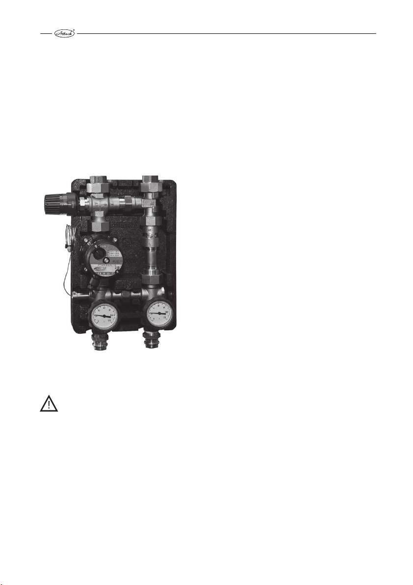
PROTECTION AGAINST CORROSION
2.4.1
The boiler must be connected with a device regulating the temperature of the boiler´s return
connection. It is suitable to use the mixing device Attack-Oventrop (Pic.3), which enables creation of the separate boiler and heating circuit. Thereby is the boiler protected against undercooling and the creation of water steam. Acids and tars in the boiler´s feeding chamber are eliminated.
The Attack-Oventrop device keeps the constant temperature of the return heating water flowing
into the boiler over 65 °C by setting the thermostatic head to the level 5–6.When the individual
thermal regulation mixing valve is used, it is possible to control the temperature of the heating
water independently on the temperature of water in the boiler by setting the flap. The temperature in the boiler has to be kept in the range of 80–90 °C.
Device ATTACK Oventrop
Pic. 3
CAUTION! If a protection device against corrosion is not intalled in the system or the device does not work properly, it may lead to creation of an aggressive condensate and
thereby boiler damage. Protection against condensation must be used during boiler
operation, otherwise the warranty is void!
12
Page 14

CHIMNEY
2.4.2
Connection of the appliance to the chimney hole must be always done with in line with local
regulations and the appropriate chimney association. The chimney must generate sufficient
draught and take the flue gas out into the atmosphere under all operating conditions.
Correct dimensions of the chimney are important for correct boiler function, because the burning, output and boiler life-time are influenced by the draught. The chimney draught directly depends on its diameter, height and surface finish of the internal wall. It is not allowed to connect
any other appliance to the chimney, where the boiler is connected. Diameter of the chimney
must not be smaller than the connection part on the boiler. The chimney draught must achieve
the precribed values, but it cannot be too high, not to decrease the boiler output and interrupt
the burning (flame). If there is too strong draught, install the throttle flap into the chimney hole
between the boiler and the chimney.
Minimum dimensions of the chimneys:
20×20cm min. height 7 m
∅
20 cm min. height 8 m
15×15 cm min. height 11 m
∅
16 cm min. height 12 m
The exact chimney dimension is defined by the STN 73 42 10. The prescribed chimney draught is
given in the Technical parameters.
FLUE GAS CONNECTION OF THE BOILER
2.4.3
The flue connection must lead into the chimney hole. If it is not possible to connect the boiler to
the chimney hole directly, then the appropriate extension should be as short as possible, of up
to 1 m length, without any additional heating area and it should ascend in direction to the
chimney. It is suitable to insulate the flue connection to achieve the sufficient flue gas temperature and to prevent the condensation in the chimney. The flue connection must be mechanically
tight (it should be mounted to the boiler and tightly fixed by screws) and tight against the flue
leakage. There must be possibility of the internal cleaning. The flue connections must to lead
through the foreign dwelling or commercial premisses. The internal diameter of the flue connection must not taper in direction to the chimney. It is not suitable to use the elbow connectors.
There must be a „T“connection of the flue outlet to the chimney, to ensure that the condensate
must leak into the appropriate tray and not into the boiler.
The flue connection must comply with local regulations and only be conducted by authorised
and trained personel.
CONNECTION TO THE ELECTRICITY MAINS
2.4.4
The boiler is connected to the electricity mains of 230V/ 50Hz/16A by an electrical cord with
plug. In the case of need, the power supply cord of the M type must be replaced with an adequate one by the service organization.
The appliance must be placed in such a way that enables the user to reach the connection plug.
The boiler must be connected to the 16A socket circuit by a circuit breaker (following the STN EN
60 335-1 + A11:1997).
13
Page 15
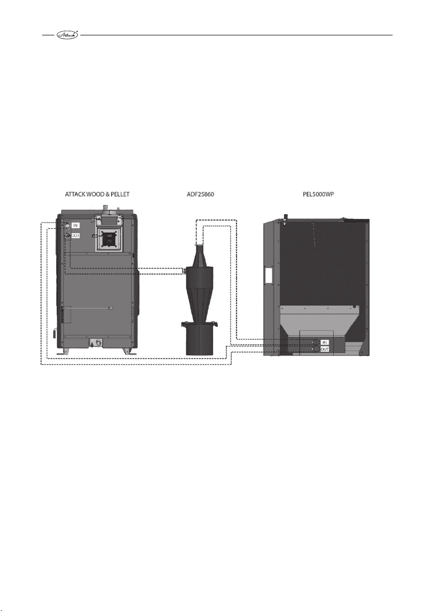
CONNECTION OF THE EXTERNAL PELLET TANK
2.4.5
The boiler is equipped by a motor for vacuum pellet feeding from an external tank. The external
tank can be placed nearby the boiler or in another room but always the max. length of the suction tube is 10 m. The tank can be in the higher position, but not in the lower position than the
boiler. There must be used the ATTACK PEL5000WP pellet vaccum tank. The suction tubes
(∅ 50 mm) and the vacuum tank is ordered as accessories together with the boiler. At the same
time there must be mounted the cyclonic separator ADF25860 which is supplied together
with the boiler.
Pripojenie nasávacej a výfukovej hadice je na kotle označené ako „PELLET IN“ a „PELLET OUT“ na
zadnej strane kotla. For correct mounting of cyclonic separator with the boiler and pellet vacuum tank see chart no. 1 below.
Chart no. 1: Boiler mounting with pellet vacuum tank and cyclonic separator
LEFT DOOR VERSION
2.4.6
There is an option of the ATTACK WOOD&PELLET boiler with the left door (door hinges on the
left side). It can be done before the boiler start-up or later, when the boiler is not in service. The
main, upper, middle and bottom door can be turned without need of the any additional tools.
Everything necessary is contained in the boiler. Use the standard tools: cross screwdriver, fork
key of 8 – 13 mm or nut, allan key of 6 mm, etc. The adjustment has to be done by a trained
worker.
CHOICE AND WAY OF CONNECTION OF THE CONTROL AND SAFETY
2.4.7
ELEMENTS
The boiler is delivered with the basic regulation and control equipment. This equipment must be
completed with other items (not delivered with the boiler) in line with local regulations, that
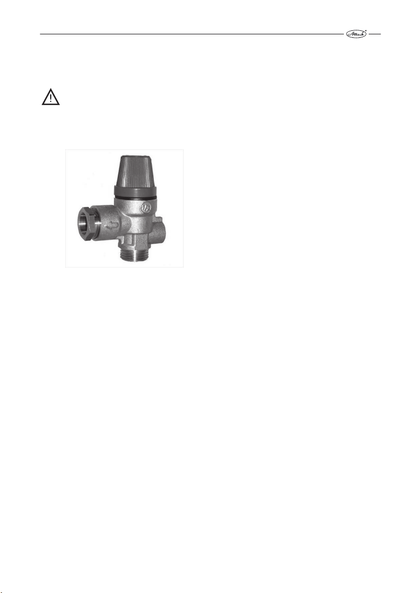
have to be installed in the heating circuit – particularly the following ones: safety valve (Pic. 4)
against exceeding the permitted pressure in the heating system (prescribed value: 2,5 bar), valve
of the boiler aftercooling loop to take the excessive heat from the boiler into the waste and deaeration valve for the correct boiler function. The volume of the expanse vessel in the system has
14
Page 16
to be defined by a designer of the heating system according to the system design and local regulations. The electrical installation related to the additional boiler equipment has to be done by
a specialist and following the valid regulations.
DANGER! The heating system must be equipped with a safety valve against exceeding
the pressure in the boiler (2,5 bar). This valve should be placed on the flow connection of
the boiler, always installed in front of the boiler closing valve (or in front of the Oventrop
– scheme 1). If the safety valve is not functional, the excessive pressure will not be
eliminated and it may cause an explosion of the boiler.
Safety valve against the overpressure
Pic. 4
15
Page 17
Boiler protection against overheating
Every wood gasifying boiler must be fitted with a functional aftercooling circuit. The appropriate
valve ensuring this function can be ordered as an accessory. On the pic. 5 you can see the correct
installation of the valve of the aftercooling circuit.
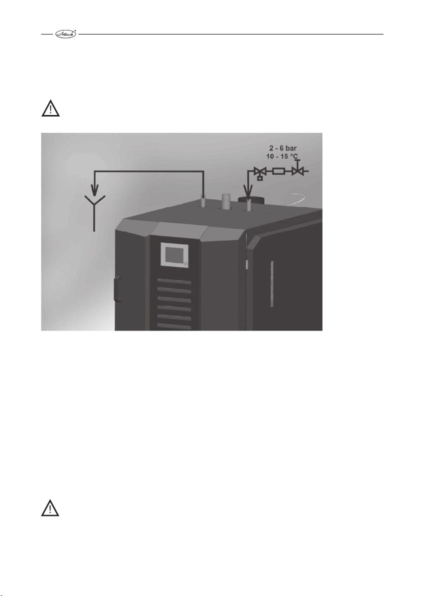
DANGER! Following the norm EN303-5, the aftercooling circuit against overhetaing
must not be used for other purpose than the boiler protection against overheating.
Connection of the thermostatic valve to the aftercooling loop
Pic. 5
The valve must be permanently opened at the cold water inlet into the boiler aftercooling circuit. The aftercooling circuit must be connected to the functional distribution of the cooling water (e.g. to the distribution of the cold water in the water supply network) with the temperature
of 10 – 15 °C and operating overpressure of 2 – 6 bar, ensuring the safe operation even by
a power failure.
The thermostatic valve at the outlet of the aftercooling circuit with the sensor placed in the rear
side of the boiler protects the boiler in the following way. If temperature of the water in the boiler exceeds 95 °C, the valve fills the aftercooling circuit with the water from the water supply
network to absorb the excessive heat. For the case that the boiler gets overheated and the
thermostatic valve is open, it is necessary to ensure the permanent outtake of the warm water
from the aftercooling circuit into the waste. Functionality of the aftercooling circuit and the
thermostatic valve can be checked manually, by the manual button of the thermostatic valve.
DANGER! If the circulation of the cooling water through the aftercooling circuit is
not ensured, when the thermostatic valve is open, there is a danger of the boiler
damage! The warranty is not valid in such a case.
16
Page 18

CONNECTION TO THE ACCUMULATION TANKS
2.4.8
The accumulation tanks are connected to be warmed and the accumulated heat is continually
used according to the requirements of the heated space. When the boiler operates at full output,
the accumulation tanks are heated to 80–90 °C. Usage of the accumulation tanks together with
the boiler ATTACK WOOD&PELLET brings several advantages. The main advantages are: prolonged life of the boiler, cleaner operation, minimal creation of acids and condensate, smaller
frequency of the fuel loading, lower probability of the boiler overheating and fuel saving.
The recommended volume of the accumulation tank for the boiler ATTACK WOOD&PELLET 25 is
2.000 l (the min. volume is 1.250 l). By full load of the hardwood (i.e. 6 hours of operation at full
output of 25 kW), the boiler produces 150 kWh of energy. This is adequate to the loading of the
2.000 l accumulation tank from 20 °C to 80 °C, if there is no other energy consumption. Thereby
it is necessary to consider the boiler usage and operation as well, when you are choosing the
accumulation tank: by the accumulation tank of 2.000 l it is necessary to load the full chamber,
by 1.000 l there is half of the chamber to be loaded (if there is no energy outtake from the tank).
Example 1:
The external temperature of environment is -5 °C and the heat loss of the building is 10 kW. The
boiler output by full operation is 25 kW. There is an accumulation tank of 1.250 l, that is discharged (its upper and bottom temperature is 20 °C). As the heating system (to cover the heat
loss) takes 10 kW from the accumulation tank and the boiler has the output of 25 kW, the accumulation tank is heated by the remaining 15 kW. The output of 15 kW, by the full load of hard
wood and during the 6 hours of operation, creates the energy of 90 kWh. This energy heats the
accumulation tank from 20 °C to 62 °C despite of the fact, that the 10 kW are being taken. This is
a safe and economical operation, when the heat is not taken into the waste (the boiler was
cooled down by the aftercooling circuit). The boiler is able to cover the heat loss for 15 hours just
by a single load of the wood.
Example 2:
The external temperature of the environment is +3 °C and the heat loss of the object by this
temperature is 5 kW. The boiler output at full operation is 25 kW. There is an accumulation tank
of 1.250 l, that is discharged (its upper and bottom temperature is 20 °C). As the heating system
(to cover the heat loss) takes 5 kW from the accumulation tank and the boiler has the output of
25 kW, the accumulation tank is heated by the remaining 20 kW. The output of 20 kW, by the full
load of hard wood and during the 6 hours of operation, creates the energy of 90 kWh. This energy heats the accumulation tank from 20 °C to 82 °C despite of the fact, that the 10 kW are being
taken. This is a safe and economical operation, when the heat is not taken into the waste, but if
the heat loss was smaller, the boiler could get overheated, because it would not be cooled
down. In such case it would come to activation of the aftercooling circuit and the excessing heat
would be taken into the waste. In case of the constant heat loss of the object (5 kW), the charged
accumulation tank would cover the heat loss approximately for the next 24 h. It means that by
a single load of wood and under the above mentioned conditions it would be possible to cover
the heat loss of the building for 30 hours.
Thereby it is very important to load just the amount of wood, adequate for heating the accumulation tank and not to overheat it, because the excessive heat would be taken into the waste
unused. Such operation would not be economical and the safety element, the aftercooling circuit would have to be activated.
The bigger volume of the accumulation tank decreases the risk of overheating and the frequency of loading the wood.
17
Page 19

Note:
TUV
300
400
600
800
000
250
500
000
The above mentioned fact is relevant by the operation with WOOD.
By the operation with PELLETS it is not relevant, as the boiler does not have to be connected to the accumulation tank, if ONLY PELLETS would be used.
Standardly delivered accumulation tanks ATTACK*
AK AS HR HRS
300 300 — —
400 400 — —
500 500 600 600 500 500 500 500
800 800 800 800
1 000 1 000 1 000 1 000
1 500 1 500 1 250 1 250 1
2 000 2 000 1 500 1 500 1
2 500 2 500 2 000 2 000 1
3 000 3 000 — — 2
4 000 4 000 — — — — — —
5 000 5 000 — — — — — —
TUVS S SS
300 — —
400 — —
600 800 800
800 1 000 1 000
1 000 1 250 1 250
1 250 1 500 1 500
1 500 2 000 2 000
2 000 — —
AK – standard accumulation tank intended for the accumulation of energy of the heating water
AS –standard accumulation tank intended for the accumulation of energy of the heating water,
equipped with a coil for connection of the solar panels
HR – combined accumulation tank for accumulation of energy of the heating water and the domestic hot water preparation
HRS – combined accumulation tank for accumulation of energy of the heating water and the
domestic hot water preparation, equipped with a coil for connection of the solar panels
* The volume necessary for the accumulation of energy can be covered by one or by several accumulation tanks. The accumulation tanks can be connected together to create the sufficient
volume of water for accumulation. Thereby, if you decide for a volume of 2.000 l, it is possible to
use one tank of 2.000 l or two tanks of 1.000 l connected together. The required way of connection is given in the chapter „Recommended hydraulic schemes of boiler connection“.
18
Page 20

3 WARRANTY CONDITIONS
The warranty for the boiler is valid only if the boiler installation was done by a person certified
under the valid norms and following the instruction manual. The company who performed the
installation must completely and clearly fill the form. If the boiler is damaged by an inexpert installation, the company who installed it has to carry the costs for repair, only use approved and
properly trained installers.
The user has to respect the instructions for operation and maintenance given in the manual. If
the instructions for operation and maintenance are not kept, the use of the boiler is unauthorised and careless or incorrect fuel is used, the warranty is not valid and the customer has to carry
the costs by damage.
The warranty is valid only in the case, that the boiler was installed and operated in the following way:
• together with device for the boiler protection against condensation ATTACK-OVENTROP
• with prescribed fuel given in the chapter „FUEL“
• with the thermostatic valve installed against the boiler overheating
• with the chimney of appropriate parameters (diameter, height) given in the chapter „CHIMNEY“
• the boiler was regularly and sufficiently cleaned as it is given in the chapter „CLEANING“
• the boiler was operated following the instructions given in this manual and not in the different way.
The warranty is valid for a complete boiler ATTACK WOOD&PELLET, except of wearing boiler
parts that are usually worn, and therefore they cannot be included into the warranty:
• glass sealing cords of the door and ash tray.
• refractory nozzle
19
Page 21

4 TECHNICAL PARAMETERS
Parameter Units AWP 25
Nominal output by wood kW 25
Nominal output by pellets kW 30
Range of the output by wood kW 12,5 ÷ 25
Range of the output by pellets kW 9 ÷ 30
Heat-exchange area m² 2,18
Volume of the feeding chamber l 160
Volume of the integrated pellet tank l 48
Dimension of the feeding door mm 230×445
Prescribed chimney draught Pa 23
Max. operation overpressure of water kPa 250
Pressure loss of water (ΔT 10 K)
Pressure loss of water (ΔT 20 K)
Boiler weight kg 860
Diameter of the flue outlet mm 150
Boiler height "A" mm 1620
Boiler width "B" mm 940
Boiler depth "C" mm 1220
Length of the feeding chamber "D" mm 580
Diameter of the flow connection " G 6/4"
Diameter of the return connection " G 6/4"
Grade of protection IP 21
El. input by a nominal output W 90
El. input by a minimal output W 32
El. input in the standby mode W < 15
Efficiency of the wood boiler % 90,5
Efficiency of the pellet boiler % 90,4
Boiler class EN 303-5:2012 — 5
Flue gas temperature by the nominal output by wood °C 156
Flue gas temperature by the min. output by wood °C 92
Flue gas temperature by the nominal output by pellets °C 130
Flue gas temperature by the min. output by pellets °C 86
Flue gas flow by nominal output kg/s 0,019
Flue gas flow by min. output kg/s 0,005
Max. noise level dB 65
Wood consumption by nominal output kg/h 7,2
Pellet consumption by nominal output kg/h 6,8
Max. length of wood logs mm 560
Time of operation by max output by wood h 6
Volume of water in the boiler l 126
Min. volume of accumulation tank l 1250
Connection voltage V/Hz/A 230/50/16
The producer, ATTACK, s.r.o. reserves right of technical changes of the products without any previous
announcement!
kPa 2,1
kPa 0,6
20
Page 22
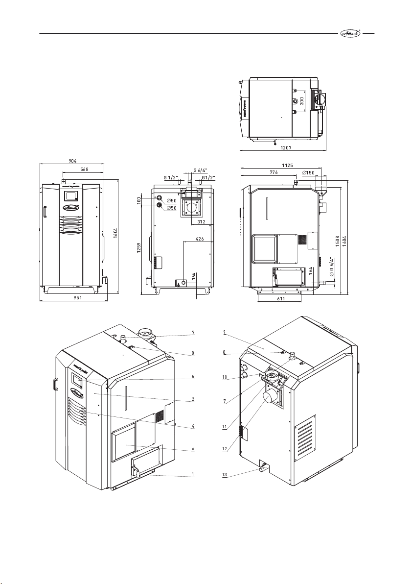
DIMENSIONS OF THE BOILER ATTACK WOOD&PELLET 25
4.1
1207
904
568
G 1/2" G1/2"
0
0
1
4
0
6
1
9
5
2
1
G 6/4"
∅
50
∅
50
312
426
4
6
1
776
1125
0
0
3
∅
150
8
4
0
0
5
6
1
1
"
4
/
6
4
G
6
1
∅
951
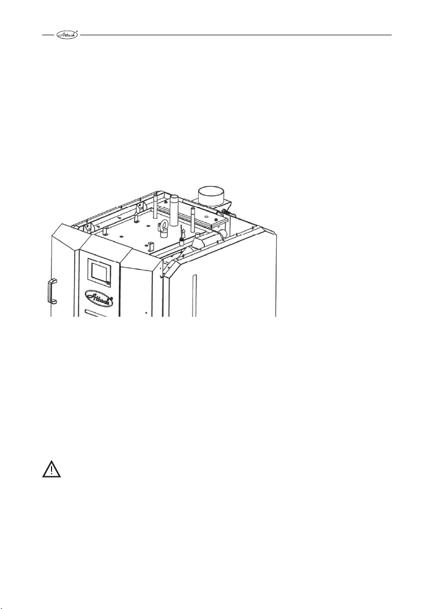
Description of particular boiler parts
Pic. 6
611
7
8
5
2
4
6
1
9
8
10
7
11
12
13
21
Page 23
1 – boiler body, 2 – main door, 3 – cover of the air inlets into the wood gasifying section, 4 – display cooling, 5 – touch display, 6 – cover of electronics, 7 – flow connection, 8 – aftercooling circuit, 9 – cover of
turbulators, 10 – lambda probe, 11 – flue connection, 12 – exhaust fan, 13 – return connection
5 REGULATION OF THE BOILER AND THE HEATING SYSTEM
IN GENERAL
5.1
DANGER! If you tun the main switch off during the boiler operation, it has no regulation.
Then, any dangerous states may cause the serious health or property damage. Always
let the fuel completely burn out and the boiler cool down before turning the main
switch off!
WARNING! Opening the upper and middle door of the feeding chamber or the bottom
door of the combustion chamber during the operation may cause accumulation of the
flammable gases and their explosion, this may cause serious damage to health or property. It is forbidden to open any door behind the main door during the operation!
EMERGENCY ACTIONS
5.2
Boiler overheating
If the boiler is in WOOD mode and it starts to overheat and the functionality of the aftercooling
loop fails from any reason, do the following:
• Do not open any door of the boiler!
• Turn the boiler off by the STOP button and confirm the red emergency message „I really
want to stop the boiler“
• Start all the pumps, heating circuits, open all the 3-way valves (attention, the max. tempera-
ture by the floor heating is 40 °C), to ensure the max. heat energy outtake from the boiler
• Leave the boiler room and close the door.
• Open the thermostatic heads on all radiators (the heating season does not make
a difference), eventually let the domestic hot water flow - run hot water tap, if the boiler is
connected for the D.H.W. preparation as well
• Contact your installer
DANGER! Never turn the main switch off, nor disconnect the boiler from the electricity mains, when the boiler gets overheated!!
22
Page 24
PREPARATION FOR THE OPERATION, FILLING THE INTEGRATED
5.3
PELLET TANK
CAUTION! Check, that the hoses of the vacuum suction are connected correctly and
airtight, before starting the pellet suction into the integrated tank.
Before starting the operation of the boiler ATTACK WOOD&PELLET for pellets, it is necessary to
suck the pellets into the integrated tank manually. Use the TEST mode, by clicking on the „vacuum suction“. Watch the level of the pellets sucked through the side control opening or in the
information menu of the PELLET SENSOR. The sufficient amount of pellets in the integrated tank
is visible through the full pellet indicator and by the green light of the PELLET SENSOR.
After this, the pellets will be sucked automatically. In the case of error you can always fill the tank
by the TEST mode.
6 BOILER START-UP
Boiler preparation for operation
The boiler must be assembled, installed and started-up only by an installer certified for the installation of the heating appliances. Before starting the boiler, it is necessary to check, if the hydraulic system is filled with water by the correct pressure, deaerated and without decreasing
pressure of the heating water. Check tightness and strength of the flue construction and functionality of the aftercooling circuit by pressing the valve manually. The boiler must be operated
in conformity with the instructions given in this manual to achieve the quality function.
CAUTION! There may come be condensation and condensate leakage by the first firing
of the boiler. This will disappear after the the first burn. It is a natural effect.
WARNING! It is necessary to be more careful, if the boiler was out of order for a longer
period (in summer or in case of failure). The pump could get blocked (and the boiler
could get overheated and the aftercooling circuit would be started), or the water could
leak out of the system. Check the correct pump function and the pressure of water in
the heating system!
See the chapter „BOILER CONTROL“about putting the boiler into operation (heating up,
loading, filling the tank with pellets, etc.).
7 DESCRIPTION OF THE SAFETY DEVICES
BASIC DESCRIPTION
7.1
Description of the main regulation of the boiler (Pic. 8):
1. Emergency thermostat with reset – boiler protection against overheating (when the temperature of 110 °C is exceeded, all the electrical devices in the boiler are disconnected, except of the circulation pump; when the temperature of the water in the boiler decreases
under 85 °C, it is necessary to demount the cover and to manually press the thermostat
button.
2. Main fuse – boiler protection against the electrical short circuit
3. Main switch – start/stop of the boiler. Unplug the whole boiler from the electrical mains.
23
Page 25

4. Combined thermo manometer. Actual information about the temperature and pressure,
independent of power supply.
Description of the main regulation of the boiler
Pic. 7
The combustion process in the boiler ATTACK WOOD&PELLET is controlled by the modern electronics, equipped with software operating on the basis of the latest knowledge in the field of the
biomass burning. There is an advanced touch screen, displaying multiple information to enable
the quick identification of the state of the boiler and its parameters. On the pic. 9 there is the
basic data display.
24
Page 26
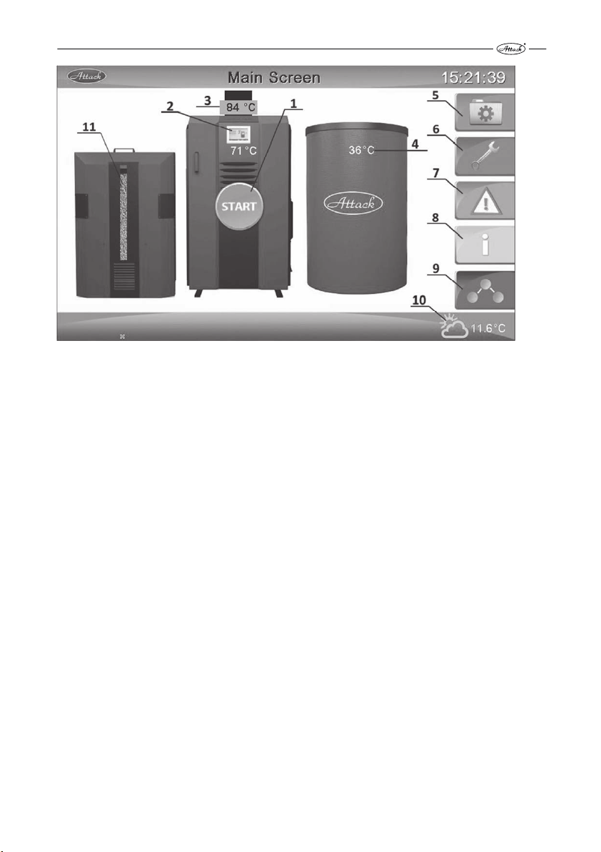
Basic display
Pic. 8
1 – Start of boiler, 2 – Boiler temperature, 3 –Flue gas temperature, 4 - Temperature of accumulation tank (optional sensor), 5 - Menu settings of parameters, 6 –General settings, 7 – Error
messages, 8 – Information menu, 9 – Heating circuit, 10 –Outside temperature (optional sensor),
11 – Pellet level in pellet tank (calculated value according to the tank’s volume)
The regulation of the WOOD burning is ensured by the Lambda probe together with the controlled rotations of the exhaust fan, controlled inlet of the primary and the secondary air, measuring the temperature of the boiler and flue gas.
The regulation of the PELLETS burning and feeding is ensured by the integrated vacuum feeder
(pellet suction from the main tank into the built-in integrated tank), sensor of the pellet presence, turnstile auger, ignition coil, photocell, fan with controlled rotations and by the automatic
cleaning.
25
Page 27
TEST MODE
7.2
Boiler ATTACK WOOD & PELLET enables to test functionality of some connected electrical
devices.
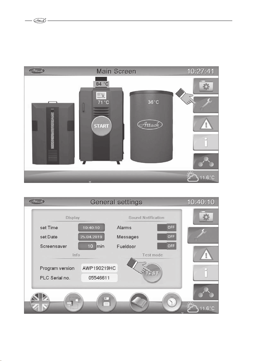
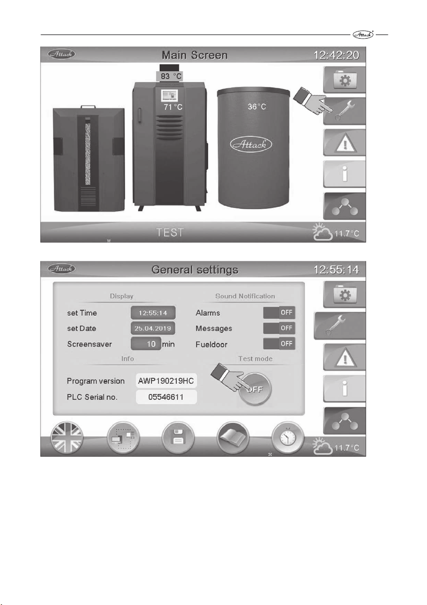
Click the button of General settings and then the button TEST for the entry into the Testmode of
the boiler (pic. 9, pic. 10).
Click on button General settings
Pic. 9
Click on displaying Test menu
Pic. 10
26
Page 28
We do the test of devices by clicking the button next to the device or by writing value in %
(pic. 11, 12, 13)
Testing activation of devices unable to be changed (modulated) and devices able to be
Pic. 11
changed (modulated)
Pic. 12
Testing activation of devices unable to be changed (modulated)
27
Page 29
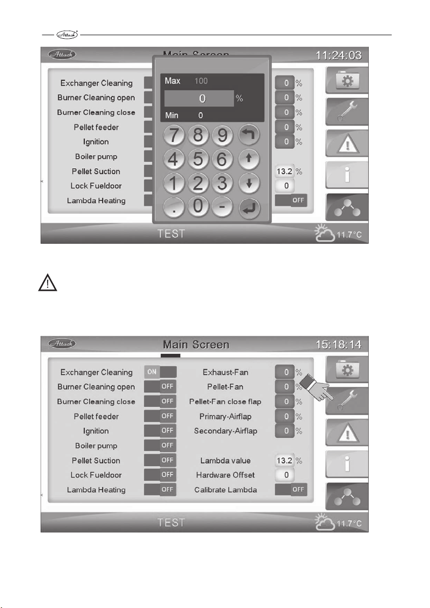
Testing activation of modulated devices
Pic. 13
CAUTION! After the end of testing of any devices it is always needed to turn off these devices.
After finishing of the testing come out from test mode with the button of service key. We get
into the Main Screen where we again click on service key and there on button OFF (see pic. 14,
15, 16)
Coming out from Test menu
Pic. 14
28
Page 30
Coming out from Test menu 2
Pic. 15
Coming out from Test menu 3
Pic. 16
29
Page 31

BOILER’S OPERATION
7.3
The boiler ATTACK WOOD&PELLET is one of combined boilers where after burning the wood out
it is not needed to make an intervention into the boiler for burning the pellets. The boiler automatically detects the burning-out of the wood and, if required for further heat production, starts
the pellet combustion in the pellet section.
The boiler works in three modes , i.e. WOOD, PELLETS and COMBI. The mode WOOD is aimed for
burning just wood and makes from the combined boiler regular wood-gasifying boiler. When
the mode is set to WOOD, the boiler controls the process of burning wood and after burning it is
shut down. With this mode it is always possible to charge the accumulation tank a day in advance and consume it gradually during the next day and night without consumption of pellets.
This type of mode is advantegous in seasons such as autumn and spring when it is possible to
cover heat losses by charged accumulation tank for several hours and days. It is not possible to
interrupt the WOOD mode at any time; it is needed to wait for burning the wood out. After burning the wood out it is possible to get into another mode.
The PELLET mode is aimed for pellet combustion, basically makes from the combined boiler pellet boiler. The boiler will operate until it reaches the set boiler temperature. The boiler is then
switched off and the burner is automatically cleaned. If the temperature in the accumulation
tank drops, the boiler is switched on again. The pellet operation mode can be switched off at any
time, but it is needed to wait until the burning the wood out in the burner and it will be cleaned
up. should be stopped and the burner cleaned up. In COMBI mode the boiler works as in WOOD
mode but after the wood burns out if there is a heat demand it automatically switches to pellets.
If the boiler is in operation for pellets, this operation can be interrupted at any time (wait for the
pellets to burn out, approx. 5 min), and start the wood operation. The reverse procedure is not
possible.
WARNING! In PELLETS mode always make sure that there is no wood or any other fuel in
the loading chamber. Otherwise you may cause uncontrolled fire and there is a risk
of serious injury or property damage.
30
Page 32

We start the boiler by pushing the button START. There will be displayed Main Screen where we
can choose among three types WOOD, PELLET, COMBI (pic. 17 and 18):
Starting the boiler
Pic. 17
Start Options
Pic. 18
Start Options:
WOOD – we choose it when we want to heat only with wood
PELLETS - we choose it when we want to heat only with pellets
COMBI – we choose in case we want the boiler to be switched into the PELLETS mode after
burning the wood out and if there will be demand for further heating
31
Page 33

OPERATION WITH WOOD
7.3.1
Use this mode, if:
You wish to operate the boiler as a WOOD gasifying boiler. When the WOOD is burned out in the
feeding chamber, the boiler is stopped (the pellet part will not be automatically started to work).
The ways to light the boiler up:
• The manual mode of lighting up the wood is used, if the boiler was heating during the day
before or if there are cinders remained in the feeding chamber.
• The automatic mode of lighting up the wood can be used after the boiler is cleaned and
there are no cinders to make it easier. The automatic mode of lighting up the wood needs
more electrical energy than the manual mode and it requires the sufficient amount of pellets
in the integrated tank.
In Start Options choose WOOD (pic. 19) andn there will be displayed options of ignition (pic. 20),
where you can choose between manual and automatic ignition.
Choosing WOOD mode
Pic. 19
32
Page 34

Choosing type of ignition
Pic. 20
7.3.1.1 MANUAL LIGHT UP OF WOOD
1. Turn the main switch on, if it has not been done yet.
2. Open the main door and the door of the feeding chamber. Check the level of ash in the
feeding chamber. If it exceeds 50 mm, clean the feeding chamber – it is not necessary to
clean the feeding chamber every day, if the ash still contains the solid cinders. The cinders
that remain in the ash contain the usable energy and they enable faster lighting up the
wood. The feeding chamber is cleaned through the middle door by the fire hook (See the
chapter 17. Cleaning).
3. Open the door of the feeding chamber and clean it. It is the best to use a fire hook and to
remove the ash ash in direction to you. Always clean the combustion chamber before
heating the boiler up!
CAUTION! If the combustion chamber is not cleaned properly, its volume is rapidly de-
creased and it may cause imperfect burning and dangerous states. Never operate the
boiler with the uncleaned combustion chamber!
33
Page 35

4. Put the paper or cardboard (the best material), rolled into tubes (Pic. 11). If there are cinders
on the bottom of the feeding chamber, put the paper or the cardboard on them.
Preparation for lighting up the wood
Pic. 21
5. Put the wood of a smaller diameter (chips of 20×20 mm) on the cardboard (pic. 12) to make
the process of lighting up faster and more stable. Put the casual wood on the fine wood in
the way enabling the free air flow. Try to use the feeding chamber in the best way to load as
much wood as possible. Load the full chamber (Pic. 13).
34
Page 36

The way to prepare the wood for lighting up
Pic. 22
Loading the full chamber
Pic. 23
6. Close the upper and the bottom door, manually light up through the middle door only.
7. Click on button START (pic. 24)
35
Page 37

Starting the boiler
Pic. 24
8. There will be displayed Start Options where you choose the option WOOD (pic. 25)
Choosing WOOD mode
Pic. 25
36
Page 38

9. After choosing WOOD mode there are displayed Start Options where we choose manual ig-
nition (pic. 26). The exhaust fan will start to work and the wood will be prepared for lighting
up.
Lighting up the wood in the wood gasification part:
Pic. 26
1 - manual starting (ignition), 2 - automatic starting, 3 – time of glowing the heating coil (by automatic ignition) , 4 – delay timeof ignition (by automatic ignition), 5 – output coils works on (by
automatic ignition)
10. Light the pellets on the bottom through the middle door by a lighter. Keep themiddle door
partly open, until the cardboard and the wood chips light up (approximately for 5 min) and
the chimney gets the draught. Afterwards, close the door. This way of heating is very quick
and it enables to heat the boiler up without any smoke. Through the pivot control opening
on the bottom door you can watch the flame created by the process of gasification. Close the
main door after verifying, that the flame was created and the boiler correctly gasifies.
37
Page 39

Displaying WOOD operation
Pic. 27
All operational information are displayed in information menu. You get into information menu
by clicking on button "i".
Entry into information menu
Pic. 28
Immediately after firing up the boiler is in Ignition phase (pic. 29).
38
Page 40

Ignition phase
Pic. 29
When the temperature rises, the boiler comes into the Pre-Heating phase (pic. 30).
CAUTION! Pre-Heating phase - phase coming when the flue gas temperature rises during the set time in parameters. If the flue gas temperature rises during another time set in
parameters the boiler crosses into Control phase.
Pre-Heating phase
Pic. 30
If the rising of flue gas temperature continues the boiler will cross into the phase of Regulation
(Pic. 31).
39
Page 41

Regulation phase
Pic. 31
Once the boiler reaches set temperature and exceeds it, then there comes Glow (Ember) Protection phase pic. 32)
Glow (Ember) Protection phase
Pic. 32
CAUTION! If the flue gas temperaturewill not rise in 30 minutes, there is written the lack of
fuel
In case you decide to turn off the boiler it is needed to wait until the fuel will burn out.
Click on button „WOOD“ (pic. 33)
40
Page 42

Mode selection
Pic. 33
There will be displayed message that the burning has already started if you really want to stop.
Then confirm that you really want to turn the boiler off (pic. 34).
Turning the WOOD mode off
Pic. 34
41
Page 43

7.3.1.2 AUTOMATIC LIGHT-UP OF WOOD
The wood can be automatically ignited by pellets, with no need to prepare the lighting-up with
paper, nor cardboard. However, it is necessary to use the wood of small diameter (wood chips of
20×20 mm).
CAUTION! The automatic light-up of the wood is a complicated process and the first trial
requires the attention of the customer. It is necessary to select the parameters of the automatic light-up carefully, to avoid the uncontrolled wood burning in the feeding chamber of the boiler. Do not use the automatic light-up of wood, if the parameters of
your chimney do not achieve the values given in this manual. The problems with the
automatic wood ignition may occur due to the cold chimney or in summer, when there is
a chimney draught naturally decreased. Thereby it is necessary to consider the automatic
wood ignition carefully in summer and by the cold chimney.
Procedure of starting up the automatic wood ignition:
1. Repeat the procedure according to 7.3.1.1, points 1 - 3.
2. Put the wood of small diameter (wood chips of 20×20 mm) on the bottom of the chamber to
make the process of heating-up faster and more stable. Put the ordinary wood on the fine
wood in the way enabling the free air flow. In the ¼ of height should be the wood laid crosswise to make a tunel to light the wood up from the pellet part (Pic. 36). Try to use the loading
chamber in the best way to feed as much wood as possible. Load the full chamber.
Preparation for wood ignition
Pic. 35
42
Page 44

Loading the wood into the chamber by the automatic light-up
Pic. 36
Loading the full chamber
Pic. 37
3. Close all door (upper, middle, bottom, main ones).
4. Click on button START (pic.38).
43
Page 45

Boiler starting
Pic. 38
5. There will be displayed Start Options where you choose the option WOOD (pic. 39)
Choosing WOOD mode
Pic. 39
6. After choosing WOOD mode there are displayed Start Options where we choose automatic
ignition (pic. 40). Before the automatic ignition choose its parameters. The exhaust fan will
start to work and the wood will be prepared for lighting up.
44
Page 46

Choosing the automatic ignition
Pic. 40
1 - manual starting (ignition), 2 - automatic starting, 3 – time of glowing the heating coil (by automatic ignition) , 4 – delay timeof ignition (by automatic ignition), 5 – output the ignition coil
works on (by automatic ignition)
The amount of power with which will be ignited the wood by the pellet section should be well
considered. By too high power there can occur excessive release of gaseous substances from the
wood and the smoke from the loading chamber into the primary air of the boiler. Therefore, we
recommend you try the automatic wood ignition with a lower power setting (approximately
30%).
After clicking on automatic ignitation there is automatically started the pellet section which will
ignite the part for wood. For displaying status information click on „i“ (pic.41).
45
Page 47

Display after activation of automatic ignition of wood
Pic. 41
Immediately after starting of the boiler it is in the Pre-Flushing phase (pic. 42).
Pre-Flushing of the burner
Pic. 42
After Pre-Flushing of the burner there comes the phase of Filling the pellets into the burner (pic.
43).
46
Page 48

Phase of Filling the pellets into the burner
Pic. 43
After Filling the pellets into the burner there comes the phase of Ignition (pic. 44)
Phase of Pellet Ignition
Pic. 44
CAUTION! In case of unsuccessful ignition there comes Ignition no. 2. It is possible to set
the number of repeated ignitions in parameters.
After successful ignition there comes the phase of Pre-Heating of pellets (pic. 45).
47
Page 49

Pre-Heating phase
Pic. 45
After Pre-Heating of pellets there comes the phase of Regulation of pellets (pic. 46).
Regulation of pellets phase
Pic. 46
After the phase of Regulation of pellets the burner shuts down and there comes Pre-Heating of
wood (pic. 47)
48
Page 50

Pre-Heating of wood
Pic. 47
Once the flue gas temperature rises the Regulation mode comes (pic. 48).
Regulation mode
Pic. 48
CAUTION! If the flue gas temperature does not rise above 90 ° C during 5 minutes during the
regulation, the boiler will report a fuel shortage (pic. 49). If the flue gas temperature does not
rise above 90 ° C for another 10 minutes, the boiler will burn out (pic. 50) and stay in standby
mode.
49
Page 51

Message Missing Fuel
Pic. 49
Burn Out mode
Pic. 50
50
Page 52

DESCRIPTION OF THE MAIN CONTROL MODES
7.3.2
The pellet operating mode is a fully automatic mode capable of burning PELLETS.
Use this mode when:
• You want to operate the boiler only with pellets
CAUTION! For functionality of operation with PELLETS it is needed to have activated
timer for the days you want to heat with pellets. The timer is activated from production.
More information you can find in article no. 12 TIMER SETTINGS.
Boiler Ignition procedure:
1. Click on button START and choose operation mode PELLETS (pic. 51 a pic. 52)
Starting the boiler
Pic. 51
51
Page 53

Choosing operation mode PELLETS
Pic. 52
After choosing the PELLET mode the boiler is automatically switched on.
Click on Information menu, there you can see all operational information (pic. 53).
Displaying operational information
Pic. 53
2. Then the mode of Pre-flushing of the burner comes (pic. 54) where the electronics checks if
the pellet tank sucked pellets. If the there are no pellets in boiler, the mode of filling starts
before starting of mode of Pre-Flushing.
52
Page 54

Mode of Pre-flushing
Pic. 54
3. After Pre-flushing there is the mode of pellet filling into the burner (pic. 55) and pellet’s ignition (pic. 56).
Mode of Filling of pellets into the burner
Pic. 55
53
Page 55

Mode of pellets’s ignition
Pic. 56
CAUTION! In case of unseccusseful ignition there comes Ignition no. 2. It is possible to set
the number of repeated ignition in advanced boiler’s parameters.
4. After pellet ignition there comes Pre-Heating phase (pic. 57)
Pre-Heating Phase
Pic. 57
5. After Pre-Heating mode there comes the Regulation mode (pic. 58) which lasts until heating
is switched off.
54
Page 56

Regulation mode
Pic. 58
Boiler shutdown options are:
1. When the boiler temperature is reached or exceeded
2. When the accumulation tank temperature is reached (if there are installed sensors in accumu-
lation tank)
3. By boiler’s timer
4. By room thermostat
5. When there is mode failure
6. After the maximum burner operating time has elapsed
Boiler shutdown from the reason boiler temperature is reached
Pic. 59
55
Page 57

Boiler shutdown from the reason the accumulation tank temperature is reached - 1
Pic. 60
Boiler shutdown from the reason the accumulation tank temperature is reached - 2
Pic. 61
6. After burning the burner will be cleaned and shut down, the boiler remains in standby mode
and waits for further switching on according to temperatures.
56
Page 58

COMBINED OPERATION MODE
7.3.3
The combined operation mode is a fully automatic mode that is able to operate the WOOD
burning or the PELLET burning, but not both at the same time
CAUTION! For automatic switching the operation from wood to pellets in COMBI mode
it is needed to have activated timer for the days you want to heat with pellets. The timer
is activated from production. More information you can find in article no. 12 TIMER
SETTINGS.
DANGER! The combined mode serves for operation with either of the fuel types – the
WOOD or the PELLETS. Never try to burn WOOD and PELLETS at once, because it may
cause uncontrolled burning, a health hazard or property damage.
Use this mode, if:
1. You are going to load the full loading chamber with wood and you wish to cover the requirement for heat with the pellet burning, after the wood burns out.
Push the button START and choose from menu mode COMBI (pic. 63).
Starting the boiler
Pic. 62
57
Page 59

Choosing COMBI mode
Pic. 63
The combined mode can start with burning the wood or burning the pellets. It is not possible to
burn both fuels (i.e. the wood and the pellets) at the same time.
After choosing COMBI mode it is needed to choose the ignition between manual and automatic
(pic. 64).
Selection of wood ignition in COMBI mode
Pic. 64
If the boiler was started with wood, pellets can be used after it burns out. The operation with
wood cannot be interrupted by the operation with pellets. The boiler struggles to burn all wood
58
Page 60

before it starts to burn pellets. The operation with pellets can be anytime interrupted (the pellets
must automatically burn down in the burner) and the wood can be loaded and burned.
CAUTION! ATTENTION! It is not allowed to put any flammable materials or objects
into the loading chamber of the boiler during the operation with pellets. The pellet
operation is stopped in 15 seconds, if the feeding door is opened.
8 DISPLAYING INFORMATION
During and also out of the boiler operation it is possible to read the information from the touch
display about the state of the boiler and particular devices (ventilators, heating coils, flaps, etc.).
By pressing the “i” button you get into the menu (Pic. 65). There are three pages in the information menu.
Display with the basic information, page 1
Pic. 65
59
Page 61

Window 1, Information
Pic. 66
The first page – the “Information 1” – gives the basic information about the boiler state: boiler,
temperature, flue gas temperature, actual value of the oxygen in the flue gas, presence of the
flame in the combustion chamber – the photocell, cycle of the pellet feeding and duration of the
feeding in one cycle)
Pic. 67
Window 2, Information
60
Page 62

The second page – the “Information 2” – displays the actual output of the exhaust ventilator and
the burner ventilator, actual rotations of the burner ventilator, position of the primary and secondary flap serving to control the wood gasification process (Pic. 23).
Window 3, Information
Pic. 68
The third page – the “Information 3” – displays the state of start or stop of the particular outputs
(if they work or not) and of the particular inputs (if they are connected or disconnected).
61
Page 63

9 SETTING THE PARAMETERS
The boiler ATTACK WOOD & PELLET enables to set general settings for correct boiler’s operation
like boiler’s temperature, flue gas temperature, temperature of heat pump’s starting etc. (pic.
69).
Entry to parameter’s settings
Pic. 69
Displaying user’s parameters
Pic. 70
62
Page 64

Parameters description:
Boiler temperature – set temperature which should be reached
Start boiler pump – the temperature when the pump is switched on
Pump delay – the time of pump delay how long the pump will be running after boiler’s shut
down
Maximum Power – output of heat pump’s in operation (in %)
Exhaust temperature Stop – the temperature below which, when the flue gas temperature
drops, the boiler will report a lack of fuel
Tank capacity - approximate time after which the external pellet tank gets empty
Set night from (hour) - if the heating circuit is connected we determine the hour of night start
when the heating circuit can reduce the temperature
Set night to (hour)- if the heating circuit control is connected we determine the hour of night
termination
After connecting the temperature sensors to the accumulation tank, the boiler can control its
operation according to the temperatures in the accumulation tank. To set the temperature in the
accumulation tank, enter the heating circuit (Pic. 71) and click on the accumulation tank (Pic. 72)
Entry to Heating Circuit
Pic. 71
63
Page 65

Displaying setting of sensors’s in accumulation tank temperature
Pic. 72
There will be displayed table with the settings of accumulation tank’s control (pic. 73).
Setting of accumulation tank
Pic. 73
64
Page 66

Connected - button to activate the control function of the accumulation tank
Upper sensor Limit - ON - the temperature below which, when the tank temperature drops, the
boiler is switched for PELLET mode
Middle sensor Limit - OFF- the temperature above which the temperature of the middle sensor
rises in the accumulation tank, the boiler switches off
10 SPECIAL SETTINGS
Boiler ATTACK WOOD & PELLET enables to set General settings. For displaying General settings
click on Service key (pic. 74).
Click for displaying General settings
Pic. 74
65
Page 67

Displaying General Settings
Pic. 75
1 – language selection, 2 – internet connection, 3 - saving and loading settings, 4 – service settings (accessible only after entering the code), 5 – timer settings, 6 – TEST MODE
Set the time / date– it is possible to set the exact time and date. If the boiler will disconnect. If
the boiler is disconnected from the power supply or the electrical supply of the boiler falls out
for some reason, it can keep the time and date for about 3 days.
Screensaver – time when the screen saver will be activated
Program version – displays information about the current boiler program version
PLC Serial no. –electronic’s serial number
Defects – after activation the boiler will do the sounds in case of system defects, failures
Alarms - after activation the boiler will do the sounds in case of alarms
Fueldoor – after activation the boiler will do the sound when the fueldoor is not closed properly
66
Page 68

11 INTERNET CONNECTION
The boiler can be connected to the internet by the LAN and it can be regulated through the remote control. The control is available via the local network and via internet as well. It is necessary
to have the IP address from the internet provider to have an access from internet.
For displaying General Internet connection settings click on Service key and button Internet
connection Pic. 76 a Pic. 77.
Click for displaying General Settings
Pic. 76
Click on button Internet connection
Pic. 77
67
Page 69

1. Connect the Ethernet cable to the connector on the back of the power cable
2. Set the correct network connection parameters via the DHCP button, where your router
assigns the IP address to the boiler (enter it manually if you have a static IP address)
IP address settings
Pic. 78
The boiler can also be controlled and accessed via a smartphone, namely:
Android: Desktop 169
iOS: Mocha VNC Lite
Destination port: 5900
Password: attack
The boiler can also be controlled and accessed via a computer, via program:
VNC Viewer (napr. UltraVNC)
WARNING! If you have set up automatic IP address assignment via DHCP in the router,
the IP address may change.
68
Page 70

12 TIMER SETTINGS
Timer enables to set exact times in days of heating with mode PELLETS or COMBI in operation
for pellets.
For displaying boiler’s timer click on service key and then on symbol of timer (pic. 80).
If the timer is not activated in PELLET mode the boiler will not start up. The timer is activated
from the factory.
Click for displaying General Settings
Pic. 79
Click for timer displaying
Pic. 80
69
Page 71

Timer for exact days activate by clicking on exact day (Pic. 81).
Timer Settings
Pic. 81
CAUTION! In case you do not have activated timer for som day the heating with pellets
will be not possible.
The other timer pages only work when external heating circuit modules are connected.
13 SOFTWARE UPDATES
Software applied in electronics can be updated. The latest software can be requested directly from ATTACK. To update:
- new software is available in ZIP file, there is another folder
- copy all files from the folder to a blank USB max. 2 GB (USB must be formatted to FAT32)
- switch off the boiler with the switch
- insert the USB stick with the software into the boiler display
- switch on the boiler with the main switch and wait
- the ATTACK logo appears on the display, followed by a black screen with white commands
- at the end of the installation, "Please select USB (Boot reboots)" in English (Please remove
USB media) (pic. 82)
- new software will be installed after boiler restart
WARNING! Never install new software while the boiler is operating.
70
Page 72

New Software Update
Pic. 82
71
Page 73

14 FACTORY SETTINGS AND FILES LOADING
If the boiler malfunction has occurred and the boiler is in a state where it is not possible to remove the malfunction or to select the desired boiler mode, the boiler must be restartedť. We
enter into General settings and click on floppy disk of the boiler (pic. 84). The boiler will reset
into factory settings.
Click for displaying General Settings
Pic. 83
Click on floppy disk for reset of settings
Pic. 84
72
Page 74

The boiler enables to download on USB key files from operation. Simply insert a blank USB into
the boiler display during operation or shortly after operation and wait for 10 seconds. The files
are stored on the USB stick. In case of any problem, send us files from the boiler operation (Pa-
rameters.txt, Boiler_log.xls and Boiler_log_old.xls). We can then analyze the operation of the
boiler from the day and the day before you have used the boiler.
15 FAULTS OF THE BOILER ATTACK WOOD & PELLET
Damage of lambda probe
The boiler must heat the lambda probe after starting of heating and the probe must show 21%
oxygen within 3 minutes. If it does not happen it is necessary to test the lambda probe in the
Test mode of the boiler, where it must reach 21% oxygen after 1 minute of heating up. If it does
not reach the desired value then it is probably damaged.
Emergency thermostat out of order
If the emergency thermostat is out of order there is the message on display. It is needed to check
it and possibly push it back However, this message is also displayed if fuse F10 on the main con-
trol board of the boiler is damaged. Fuse types are written on the transformer on the board.
The pump is not running but it indicates operation on the display
With such an error, fuse F6 on the main control board of the boiler may be damaged. Fuse types
are written on the transformer on the board.
16 BOILER MAINTENANCE
To ensure the correct boiler function during its life, it is necessary to do the maintenance. The
frequency of the maintenance depends on the frequency of operation and usage of the boiler.
The maintenance of the heating system and the boiler
The level of the water in the system has to be checked and eventually filled at least once in 14
days.
If the boiler is out of order during the winter period, the water could freeze in the system. Thereby it is better to empty the system or to fill the antifreeze mixture. Otherwise should be the water removed from the system just in the necessary cases and for the shortest time possible.
After the end of the heating season it is necessary to clean the boiler and to replace the damaged parts. Undo the ventilator two times a year and clean the radial impeller and the air chamber of the ventilator.
Tightening the hinges and exchange of the sealing cord of the door
The cords of the door are losing their elasticity by the ordinary operation and thereby they decrease their tightness. To increase the tightness when doing the maintenance, it is possible to
change the position of the cord in direction into the boiler and to make it more pressed. When
the cord totally loses its elasticity, or when the hinges cannot be shifted further into the boiler, it
is necessary to exchange the cord. Remove the old sealing cord by a screw driver and clean the
groove, where it was placed. Take the new cord and place its ending into the horizontal parts of
the groove. Use your hand or the hammer to press the cord into the groove around the door.
Release the hinges and find the appropriate position of the hinges according to the door.
73
Page 75

17 BOILER CLEANING
To ensure the correct boiler operation and the appropriate comfort and life, it is necessary to
clean it regularly.
CAUTION! Always clean the boiler regularly and properly, otherwise it my cause decreased boiler life or wrong burning. If the boiler is not cleaned regularly and sufficiently, the warranty is not valid.
The boiler must be cleaned regularly and properly, every 3–5 days, because the ash accumulated
in the feeding chamber or the combustion chamber together with the condensate and tar significantly decrease the lifetime, output and efficiency of the boiler.When there is more ash, there is
not enough space for fuel burn-out and the holder of the ceramic nozzle could get damaged
and thereby the whole boiler would be damaged. Remove the ash and soot through the bottom
opening. Open the bottom door and clean the bottom space form dirts. The frequency of cleaning depends on the quality (humidity) of wood and the intensity of heating, chimney draught
and other conditions. We recommend to clean the boiler 1× a week. Do not take the refractory
piece out, when the boiler is being cleaned.
It is necessary to clean the following places in the below mentioned intervals:
• feeding chamber of the gasification part (every 3 days)
• combustion chamber of the gasification part (everytime before loading)
• space under the combustion chamber of the gasification part (everytime before loading)
• removable ash tray of the pellet part (depends on a boiler usage, but at least every 2 weeks).
• burner grate (2× a year)
• pellet chamber (1× a year)
• radial impeller of the ventilator (2× a year)
• air chamber of the vetilator (2× a year)
• pipes of exchanger (1× a year, it is necessary to undo the turbulators)
• integrated pellet tank from the residual pellet powder (depends on the operation, at least 1×
a year)
• filter of the integrated tank (1× a year)
Feeding chamber and combustion chamber cleaning
Pic. 85
74
Page 76

18 ASSEMBLY AND DISSASSEMBLY OF THE REFRACTORY
ITEMS
The estimated lifetime of the refractory pieces is the same as the lifetime of the boiler. Thereby it
is not necessary to disassembly them for exchange, if they are not damaged.
Pic. 86
Assembly and disassembly of the refractory pieces
On the pic. 86 you can see how to assembl the refractory pieces.
Assembly of the refractory items:
Assembly the refractory items in the correct order. As the first, insert the item marked as the nr. 1
through the bottom door on the water rib and shift it totally rearwards.Then, insert the item
number 2 (through the bottom door as well), put it on the water rib and shift it snugly to the
item number 1. Prepare the sealing cord, put the 300 mm part on the rear side of the item nr. 1.
Fit 2 pcs. of 75 mm vertically to ensure, that secondary air will not flow into the item nr. 3.
Put the item nr. 3 on the item nr. 1 and shift it rearwards. Insert the item nr. 4 with the arrow in
direction to the internal part of the boiler. Insert the refractory nozzle marked as the nr. 5. Then,
tighten the upper sides of the refractory pieces nr. 3 and 4. Tighten the nozzle nr. 5 by a special
INCONEL cord, which is more resistant against temperature.
75
Page 77

19 TABLE OF RELATION OF THE RESISTANCE AND THE TEM-
PERATURE OF THE SENSOR PT 1000
The characteristics relates to the boiler temperature sensor and to the flue gas temperature sensor as well:
Temperature [C] Resistance [Ω]
-20 921
-10 960
0 1 000
10 1 039
20 1 077
30 1 116
40 1 155
50 1 193
60 1 232
70 1 270
80 1 308
90 1 347
100 1 385
110 1 422
120 1 460
130 1 498
140 1 535
150 1 573
160 1 610
170 1 647
180 1 684
190 1 721
200 1 758
210 1 795
220 1 831
230 1 868
240 1 904
250 1 940
By measuring the resistance of the sensor and the temperature using the energy meter you can
easily check, if the sensor is broken and is achieving the correct characteristics. If the sensor indicates the values that are significantly different from the above given characteristics or if it does
not indicate anything, it could be faulty and it should be replaced.
CAUTION! The sensors of the boiler temperature and the flue gas temperature have the
same characteristic, but the different temperature resistance. Thereby they are not in-
terchangeable!
76
Page 78

20 ELECTRICAL CONNECTION SCHEME
Description of the electrical scheme:
CL – motor of the burner cleaning
FL – flap of the air inlet into the burner
HS – ignition coil
F – female
M – male
FAN – ventilator of the burner
HALL – sensor of rotations of the burner´s ventilator
PH – photocell
GND – grounding
P – servogear of the primary air of the gasification part
S – servogear of the secondary air of the gasification part
M1 – motor of the vacuum pellet supply
M2 – motor of the gear for turbulator cleaning
M3 – exhaust fan
EL – electrical lock
MD – end-switch of the main door
FD – end-switch of the door of the feeding chamber
CARD – place for a memory card with software
LAN – place of the internet connection
STB – emergency thermostat
Tex – flue gas temperature sensor
Tb – boiler temperature sensor
LS – lambda probe
PS – sensor of the pellet presence
BR – burner
EMC – filter
L – phase
N – neutral
PE – grounding
S – signal
Colours of conductors:
A – black
B – blue
C – green-yellow
D – red
E – white
F – brown
G – yellow
H – green
J – grey
77
Page 79

D
B
A
P
S
E
D
A
E
D
BR
B
F
HALL
FAN
B
A
FL
EAD
~
+
-
B
A
B
A
E
A
B
C
F
3
9
PE
6
+24
2
8
7
N
N
5
L
4
L
1
F
3
6
5
2
L
N
1
4
S
+10V
F
1
2
PE
~
3
+22V
H
4
F
M
3
+24
9
6
PE
N
L
S
~
N
5
2
8
+
L
-
4
1
7
M
6
3
N
2
L
5
+10V
4
1
M
1
2
PE
H
+22V
F
~
E
3
4
CL
GND
C
PH
C
M4
A
E
D
A
E
D
E
X34
H
X33
F
X32
X31
F
B
X35
R
L
L
L
X13
NO
N
C
PE
NC
A
A
B
X11X12
C
N
N
PE
PE
A
B
X10
F
F
1
L
A
2
N
B
3
D
PE
4
C
C
78
Page 80

M1
F
M
1
E
D
E
1
32
D
Tex
LS
Tb
PS
E
H
A
D
EL
MD
J
E
A
X24 X23
L_O
L_C
N
PE
E
CO
A
J
E
F
A
E
X17
X16 X15
X22
X21
L
N
PE
A
A
X4
X3
L
L
X20 X19
L
N
PE
PE
X14
X18
A
B
C
X1X2
AEA
B
D
A
X27 X26
X29
X30
X28
L
N
PE
A
A
B
B
X9
X8
X25
L
L
N
N
PE
PE
A
B
X7
X5
X6
D
D
FD
D
D
B
X36
F
X37
E
H
L
N
PE
PE
CARD
G
LAN
EMC
MF
MS
STB
LAN
ES
M
M
1
L
A
2
B
N
3
PE
4
M3
D
C
M2
N
B
L
A
FM
1
1
N
2
L
33
B
A
79
Page 81

21 OVLÁDANIE AUTOMATICKÉHO KOTLA
The boiler enables to control switching on of the automatic boiler after burning all fuel out without the installation of additional modules. The condition of automatic boiler start function is
the temperature sensors in the accumulation tank are correctly installed.
For activation of starting function of the boiler click on symbol of heating circuit (pic. 87).
Click for displaying Heating circuit
Pic. 87
You will see a complete diagram of the entire heating circuit (pic. 88). This is the complete
scheme of heating circuit which can be controlled by boiler after installation of external modules
and elements of heating circuit.
80
Page 82

Basic description of Heating circuit
Pic. 88
To enable the automatic boiler start function, click the boiler symbol (Pic. 49 where you can see
the parameter table (Pic. 90).
Click for activation of automatic boiler’s function
Pic. 89
81
Page 83

Automatic boiler’s parameters
Pic. 90
Connected - when this function is activated, the automatic boiler switches to standby mode
Switch-off temperature - if the temperature of the upper accumulation tank sensor reaches this
setpoint, the automatic boiler switches off
Switch-on temperature - if the temperature of the upper sensor in the accumulation tank falls
below this value, the automatic boiler is switched on
Room thermostat - this function must always be activated if you want the boiler to be con-
trolled according to the storage tank temperatures. Room thermostat can be connected to the
boiler.
22 ACCESSORIES
The ATTACK WOOD&PELLET boiler is delivered functionally tested, packed and placed on
a wooden pallet.
The following accessory items are delivered:
• Instruction manual
• Warranty letter
• USB key with software
• Firehook
The following items can be optionally ordered:
• The REGUMAX regulator to control the other devices in the heating system
• Vacuum pellet tank
• Supply hoses for the vacuum pellet tank
• Ashtray suitable for the boiler cleaning
82
Page 84

23 INSTRUCTIONS FOR DISPOSAL OF THE APPLIANCE AFTER
ITS LIFETIME ENDS
Ensure the disposal of the appliance (boiler) by the waste disposal service, eventually use the
regulated waste dump, controlled by the municipal authority.
DISPOSAL OF PACKAGING
23.1
Dispose the packaging by the waste disposal service, eventually use the regulated waste dump.
24 SERVICE PARAMETERS SETTINGS
A service code is required to set service parameters. Click on General Settings (pic. 91)
WARNING! Do not modify the boiler service parameters unless you have the privilege to do so. Incorrect parameter setting may result in incorrect boiler operation, too
low boiler temperature and tar formation or too high boiler temperature. In both cases
there is a risk of fire.
Click for the entry for General Settings
Pic. 91
Then click on symbol of book (pic. 92), there will be displayed the keypad where we will enter
the service code "7319" (pic. 93).
83
Page 85

Entry into Service parameters
Pic. 92
Access to Service parameters
Pic. 93
After entering the service technician's access code, the advanced boiler parameters are made
available.
84
Page 86

Service parameters, page 1
Pic. 94
85
Page 87

Boiler temperature – the boiler should reach this temperature.
Start boiler pump - the pump will be switched on after reaching this temperature
Pump delay – pump off time after boiler shutdown
Maximum power of burner - determines the output of the burner
Exhaust-fan maximum power - determines the maximum output of the exhaust fan
Exhaust-fan minimum power - determines the minimum output of the exhaust fan
Exchanger cleaning worktime - is tme that the exchanger will be cleaned by turbulators
Exchanger cleaning interval - determines how often the exchanger has to be automatically
cleaned by turbulators
Pic. 95
Service parameters, page 2
Ignition retry numbers - if the first ignition is unsuccessful, further ignition attempts are made.
The number of ignition attempts is entered here
Maximum Power - the maximum power the burner should achieve
Maximum Ignition time– indicates the maximum acceptable time during which the heating
spiral will be turned on and the fan to ignite the pellets. If the pellets are not ignited during this
time, a repeated ignition process or failure is reported
Starting Feeding time 1 – is the time that the pellet feeder pours a certain amount of pellets
down into the burner for the first time
Starting Feeding time 2 – is the time that the pellet feeder fills a certain amount of pellets into
the burner if the pellets are not ignited during the Maximum Ignition time
Burner Cleaning worktime - duration of the automatic burner cleaning
Photocell Fire on – when the boiler exceeds this value it evaluates that the pellets have already
been ignited in the burner
86
Page 88

Service parameters, page 3
Pic. 96
Photocell Fier off – if the value of the flame intensity in the burner drops below this value, the
boiler evaluates that the flame has been lost in the burner, i.e. the process of burning is stopped.
The boiler evaluates this as an error
Difference boiler temperature Start - determines how many degrees the boiler temperature
must fall below the set temperature so that the boiler is switched on again (only in PELLET
mode)
Burn-On time after ignition - is the time it takes for forming of a stable layer of pellets in the
burner, followed by an increase in performance
Max. Combustion time- the maximum continuous burning time of the pellet burner after which
time the burner is automatically cleaned
Exhaust fan Regulation max. Power - determines the maximum output of the boiler exhaust
fan in PELLET mode
Exhaust fan Regulation min. Power - determines the minimum output of the boiler exhaust
fan in PELLET mode
Burn-Off time – is the maximum time after which, even if the pellets have not burnt in the
burner, the burner will be cleaned
Feeding cycle at 100% power - is the pellet feeding cycle to the burner
87
Page 89

Service parameters, page 4
Pic. 97
Feeding time at 100% power - is the part of the cycle during which pellets will be delivered to
the burner
Protection of burner fan - when this function is activated the boiler checks the functionality of
the pellet fan, shuts it down in the event of a malfunction or clogging and shows an error
Pellet-Fan during ignition - it can only be set by the manufacturer or the service organization it
is the burner fan power that will be during the burning time after ignition
Pellet-Fan during burnout - the fan performance during the burnout phase
Pellet-Fan max. power - only the manufacturer or service organization can set up, the maxi-
mum power of the burner fan
Pellet-Fan min. power - only the manufacturer or service organization can set up, the minimum
power of the burner fan
Size of pellet tank – indicates the size of pellet tank in seconds (during this time the turnstile
feeder will empty the volume of the intermediate pellet tank)
Automatic pellets suction – here you can turn on/turn off automatic pellet suction
88
Page 90

Service parameters, page 5
Pic. 98
Number of suction retries – the number of suction repeats in failed attempts
Turbine max runtime - determines how long a vacuum fan will suck in pellets without a break
Turbine rest time- determines how long the turbine will have a pause in suction after which it
will be switched on again
Power regulator worktime – control time PID control model (set from factory)
Power regulator P – Part– proportional part of PID control model (set from factory)
Power regulator D – Part - differential part of PID control model (set from factory)
Power regulator I – Part – integral part of PID control model (set factory setting)
Buffer uninstalled - after activation of this function the boiler will be controlled according to
the temperature of the accumulation tank
89
Page 91

Service parameters, page 6
Pic. 99
Upper sensor Limit - ON - is the temperature below which the upper sensor temperature of the
accumulation tank must decrease to switch the automatic boiler on
Middle sensor Limit - OFF - is the temperature which when the middle sensor of the accumulation tank reaches the automatic boiler switches off
Difference boiler temp. Power Regulation- is the temperature of the boiler by which the actual boiler temperature has to decrease compared to the set temperature in order to restart the
exhaust fan
Exhaust temperature start heating - is the flue gas temperature according to which the boiler
evaluates that the wood has been successfully ignited
Exhaust temperature start regulation - is the flue gas temperature, according to which the
boiler evaluates that the boiler has entered the regulation state
Primary-Airflap Max. Open - only the manufacturer or service organization can set up, is the
maximum opening of the primary flap
Secondary-Airflap Max. Open - the maximum opening of the secondary flap
90
Page 92

Service parameters, page 7
Pic. 100
Secondary- Airflap Min. Open - the minimum opening of the secondary flap
Secondary- Airflap Ignition - the flap position that will be set when the wood is ignited
Secondary- Airflap Pre-Heating - the position of the secondary flap that will be set when the
boiler is in Pre-Heating phase
Ignition max. Time - the time during which the flue gas temperature must reach the flue gas
temperature of the wood igniter. If this temperature is not reached, the boiler will be shut down
and the boiler report a fuel shortage
Exhaust temperature max. power - the flue gas temperature that the boiler will achieve at
maximum wood power
Exhaust temperature min. power - the flue gas temperature that the boiler will achieve at minimum wood power
Exhaust temperature Stop - is the flue gas temperature below which, when the flue gas temperature drops, the boiler will report a fuel shortage
Exhaust-Fan Autom. Ignition – fan output during automatic wood ignition with pellets
91
Page 93

Service parameters, page 8
Pic. 101
Primary-Airflap Autom. Ignition – can only be set by the manufacturer or service organization,
the primary flap position that will be set during automatic wood ignition with pellets
Secondary-Airflap Autom. Ignition – can only be set by the manufacturer or service organization, the secondary flap position that will be set during automatic wood ignition with pellets
Oxygen setpoint max. power - the oxygen value by which the boiler will control the combustion process at maximum power
Oxygen setpoint min. power - the oxygen value by which the boiler will control the combustion process at minimum power
Difference boiler temperature Start - after the boiler temperature drops below this set value,
the boiler is switched on
Difference boiler temperature Stop - after exceeding the set boiler temperature by this set
value, the boiler is switched off
Set night from (hour) - if the heating circuit is connected we determine the hour of night start
when the heating circuit can reduce the temperature
Set night to (hour) - if the heating circuit control is connected we determine the hour of night
termination
92
Page 94

25 THE ORIGINAL ES DECLARATION OF CONFORMITY
POZ-027/041017
I, Rudolf Bakala, the corporate representative of the ATTACK, s.r.o. company, declare, that the products mentioned
below fulfil requirements of the technical prescriptions, under conditions specified for using they are safe, they are
produced in conformity with technical documentation and with the norms and regulations given in this document.
Manufacturer: ATTACK, s.r.o., Dielenská Kružná 5020, 03861 Vrútky, Slovak Republic
Place of manufacture: ATTACK, s.r.o., Dielenská Kružná 5020, 03861 Vrútky, Slovak Republic
Product: Warm-water combined boiler for solid fuel and pellets
Type: ATTACK WOOD&PELLET 25
Description: Warm-water combined boiler for wood logs and pellets combustion. It is intended to be a heat source
for dwelling houses and similar objects. The boiler is constructed to work on principle of wood gasification by utilization of the exhaust fan, which sucks the flue into the chimney. The boiler is equipped with automatic burner for
the combustion of the prescribed fuel. The burner contains automatic electric ignition, optical control of combustion and compressed air intake fan. The pellets are automatically delivered to the burner grate by means of a turnstile feeder.
The following European Directives are related to the products:
-
Directive of the European Parliament and of the Council of Europe 2014/35/ES
-
Directive of the European Parliament and of the Council of Europe 2014/30/ES
-
Directive of the European Parliament and of the Council of Europe 2006/42/ES
List of the Harmonized Norms, used by consideration of conformity:
-
CSN EN 303-5:2013 – Central heating boilers – Part 5: Central heating boilers for solid fuels, with manual and
automatic delivery, with a rated thermal output not exceeding 500 kW - Terminology, requirements, testing
and marking
-
CSN 06 1008:1997 - Fire safety of thermal equipment
-
STN EN 60335-1 ed.2:2013 – Electrical appliances for households and the like - Safety- Part 1: General require-
ments
-
STN EN 60335-2-102:2007 - Electrical appliances for households and the like - Safety- Part 2-102: Specific requi-
rements for appliances burning gaseous, petroleum and solid fuels containing electrical connections
-
STN EN 62233:2008 - Methods of measuring electromagnetic fields of appliances for households and similar
devices with regard to exposure of persons
-
STN EN 55014-1 ed.3:2007 - Electromagnetic compatibility - Requirements for appliances for households, power
tools and similar appliances - Part 1: Radiation
-
STN EN 61000-3-2 ed.3:2006 - Electromagnetic compatibility (EMC) - Part 3-2: Limits – Limits of radiation of
harmonic parts of current (devices with input phase current <= 16 A)
-
STN EN 61000-3-3 ed.2:2009 - Electromagnetic compatibility (EMC) - Part 3-3: Limits - Limiting changes, voltage
fluctuations and flicker in low voltage public grids for equipment with rated current <= 16 A, which is not subject to a conditional connection
-
STN EN 61000-6-2 ed.3:2006 - Electromagnetic compatibility (EMC) - Part 6-2: Generic standards - Resistance to
the Industrial Environment
-
STN EN 61000-6-3 ed.2:2007 - Electromagnetic compatibility (EMC) - Part 6-3: Generic Standards - Emissions to
the residential, commercial and light industry
Notified body, who performed tests and judgement of conformity:
STROJÍRENSKÝ ZKUŠEBNÍ ÚSTAV, s.p., Hudcova 56b, 621 00 BRNO, Czech Republic, Notified body 1015
Notified body, performing inspections and control of the quality system:
STROJÍRENSKÝ ZKUŠEBNÍ ÚSTAV, s.p., Hudcova 56b, 621 00 BRNO, Czech Republic, Notified body 1015
Last double figure of the year, when the CE marking was placed on the product: 17
In Vrútky: 4. October 2017 ..............................................................................................
Rudolf Bakala, Executive manager ATTACK, s.r.o. Vrútky
93
Page 95

Information about processing of personal data
Dear Customer,
You provide us your personal information by completing and sending the Boiler start-up recordand our company becomes your personal data manager in relation to you.
We hereby would like to inform you why and how we process your personal information, how
we collect your personal information, for what purpose we handle it and the legal basis of such
processing, how we handle personal data and what your rights are in relation to processing your
personal data.
Please read the following information carefully before providing us your personal details.
In case of any questions related to the processing of your personal data, please do not hesitate
to contact us at tel. no. 00421 43 400 3131 or support@attack.sk.
Privacy Manager:
ATTACK, s. r. o., with its registered office at Dielenská Kružná 5020, 038 61 Vrútky, Slovak Re-
public
Tel .: +421 43 4003 101
Fax .: +421 43 3241 129
E-mail: export@attack.sk
Web: http://www.attack.sk
Processing of personal data
We will only process the personal information you provide to us in the Boiler start-up record, i.e.:
- Name
- Surname
- Address
- Phone
- Type and serial number of the product
Purpose and legal basis for the processing of your personal data
We will process your personal data for the following purposes and on the basis of the
following legal bases.
1) For the purposes of direct marketing, which is a legitimate interest of our company. The
legal basis here is Art. Article 6 1. Letter. (f) Regulation (EU) 2016/679 of the European Parliament and of the Council of 27 April 2016 on the protection of natural persons with regard to the processing of personal data and on the free movement of such data, and repealing Directive 95/46/EC (General Data Protection Regulation).
The proccesing based on our legitimate interest, i.e. direct marketing, is following:
Your personal data will be stored in our electronic database which is managed directly
and only by us. This electronic database is stored and secured on the property of our
company. Your personal data will be used by our legitimate interest only in order to be
able to send you an offer of our new products, especially in the event of the end of the
expected life of product which you enter your personal data in the Boiler start-up record
in if our company develops a newer and more technologically superior and better product that could replace the product in which you enter your personal data into the in the
Boiler start-up record.
Direct marketingis our legitimate interest and the one of two purposes of processing of
Page 96

your personal data, i. e. direct offer of our products sent to you.
2) The legal basis for fulfilling the extended warranty agreement on the product in which
you enter the Boiler Startup Record whereare your personal data is Art. Article 6 1. Letter.
(f) Regulation (EU) 2016/679 of the European Parliament and of the Council of 27 April
2016 on the protection of natural persons with regard to the processing of personal data
and on the free movement of such data, and repealing Directive 95/46/EC (General Data
Protection Regulation).
This processing that is required to meet the extended warranty agreement for a product
you are one of the parties will be following:
Our company provides you with an extended contractual warranty (beyond the statutory
warranty) in such situation that you comply with the warranty conditions (see the warranty conditions in the Instruction for use, in whichthere is the Boiler start-up record with
your personal data ). In order to provide you with this extended contractual warranty we
need to know who is the other party and whether you are performing your obligations
under this agreement especially the mandatory annual service inspections. Therefore we
need you to send us a record of this inspection after each annual inspection (max. 5 inspections) and we will declare in our database that you fulfill the terms of the contractual
guarantee.
Since each contract has at least two contracting parties we need your personal data to
identify you as a party and identify a specific product for the purposes of fulfilling the extended warranty agreement. We would not be able to fulfill our obligations under the extended warranty agreementproperly without these data.
Our legitimate interest and one of the two purposes of processing your personal data is
therefore the fulfillment of the contract, that is, the fulfillment of the contract for extension of the contractual guarantee.
Processing of personal data for both purposes is done manually and also in electronic information systems. However these systems are subject to rigorous and constant physical and technical
control. All persons who, on the basis of our instructions and our credentials, come in contact
with personal data in the framework of their work or contractual obligations are bound by confidentiality.
Category of recipients of personal data
We process your personal data primarily by ourselves. However it may happen that we
will have to use the services of another entity to process personal data for any of the
above mentioned purposes. In this case the relationship between us and the third party
will be the relationship between the administrator andthe processor and we will make an agreement with this processor about the processing the personal data in order to guarantee the
security and legality of processing your personal data.
Your personal data may therefore be sold to the recipient of the following categories:
a) A company that distributes our products in the territory of a member state of the Europe-
an Union in which you have purchased a product which you enter your personal data in
the Boiler start-up record in or in which such a product is put into service on your request
b) A company providing bulk mailing services
Page 97

The length of time the personal data will be stored
We will process your personal data for at least the duration of the contractual warranty (i.e. for 5
years) for the purposes of fulfilling the warranty agreement and at most for thetime of assumed
lifetime of the products for which the Boiler start-uprecord for the purposes of direct marketing.
Raising objections toprocessing of personal data
Whenever you have the right to object to our processing of your data for direct marketing purposes (see Purpose and legal basis for processing your personal data, item 1) above). If you have
an objection to our processing of your direct marketing data, by the date of your objection will
cease our processing your personal data for direct marketing purposes.
The objection to the processing of your personal data for direct marketing purposes can be sent
to us by post to:
ATTACK, s. r. o., Dielenská Kružná 5020, 038 61 Vrútky, Slovak Republic. In the objection, it is sufficient to provide the name, address and the text "I hereby raise an objection to the processing
of my personal data for the purposes of direct marketing" and your signature. We always inform
you about the accepting your requestwithout delay.
Please note that the right to object can not be invoked against our processing of your personal
data necessary for the purpose of fulfilling the extended warranty agreement.
Your other rights related to the processing of personal data
Please note that you also have the following rights in relation to our processing of your personal
information:
• to ask for information about what personal data is processed by us,
• to request access to these data and let them update or fix,
• to require the deletion of these personal data, or the limitation of their processing,
• to raise objection to the processing of your personal data,
• the right to the portability of your personal data,
• in case of doubt regarding compliance with the obligations related to the processing of
your personal data, contact the Administrator or the Office for Personal Data Protection.
You may enforce these rights to our company by the same procedure as the right to raise objections to the processing of personal data.
Page 98

Page 99

Page 100

ATTACK, s.r.o. • Dielenská Kružná 5020, 038 61 Vrútky • Slovakia
Tel: +421 43 4003 101 • E-mail: kotle@attack.sk
Export – tel: +421 43 4003 115 • E-mail: export@attack.sk
All provid ed information is temp orary, subj ect to chang e without no tice and for in formatio nal purposes only. Variati ons in
produc t visual display are possi ble and may not match the offe r and range of e quipmen t for differe nt markets . ATTACK s.r.o.
reserves t he right to make change s to specifications an d content without prio r notice. Pictures and p roduct specifica tions are
only info rmative. Price an d offer change s are reserved .
ATTACK, s.r.o. – 06/ 2019
 Loading...