

Page 1
SQ-1
Universal Hobby
Lighting Controller
Installation Instructions
for FW3.1-16
Please read instructions completely before attaching LEDs to RC.
Product of
Page 2

Contents
LED INSTALLATION ....................................................................................3
FEATURES & FUNCTIONS .........................................................................4
POWER CONNECTIONS & SETTINGS ...................................................... 4
LEDs LEGEND .............................................................................................4
BLINK MODES .............................................................................................5
MODE 0 ALL OFF...................................................................................5
MODE 1 ALL ON ....................................................................................6
MODE 2 DIM HEADLIGHT w/ DUAL DIM TAIL/BRAKE LIGHT ............ 7
MODE 3 DIM HEADLIGHT w/ Tail/Brake, Reverse, and Backre .......... 8
MODE 4 FULL BRIGHT w/ Tail/Brake, Reverse, and Backre ............... 9
MODE 5 RANDOM FLASH ..................................................................10
MODE 6 STROBE HEADLIGHTS ........................................................ 11
Page 3
Squirrel Rev C3
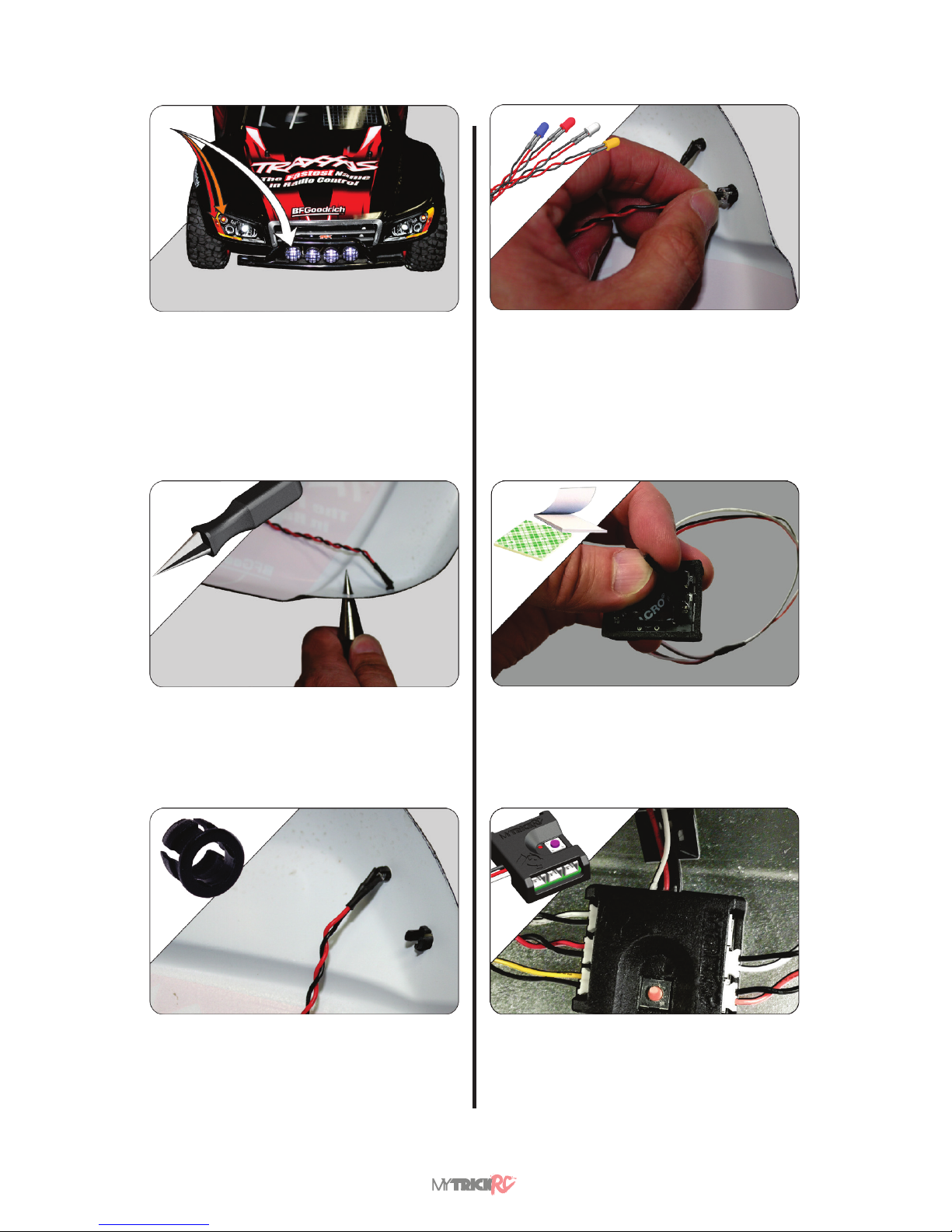
1. Choose where to install, what size, and
what color LEDs are to be used. Next, choose
the desired SQ-1 blink MODE (See Blink Mode
Section page 5).
NOTE – The blink MODE indicates
where to plug each LED into the SQ-1
controller.
2. Drill Holes for LED Holders. Be careful
to not drill the hole too large. NOTE - You can
purchase a hand drill from your local RC hobby
store. Follow carefully all safety instructions
provided with the drill.
3. Snap LED Holders into Holes.
4. Insert LEDs into LED Holders. It is
recommended to apply a pliable glue, such as
Zap Goo or Shoe Goo, liberally making sure the
glue contacts the body, the LED and LED wires.
The glue should strengthen the wires and help
the LEDs last longer.
NOTE - The proper glue may be
purchased from an RC hobby store.
LED INSTALLATION
5. Attach SQ-1 Controller to vehicle using it’s
double back adhesive or using the breakaway
mounting tabs.
6. Connect LEDs to the SQ-1 Controller
NOTE: Connect each LED depending on the
desired blink MODE. See Blink Mode Section on
page 5.
Page 4
www.MyTrickRC.com 4
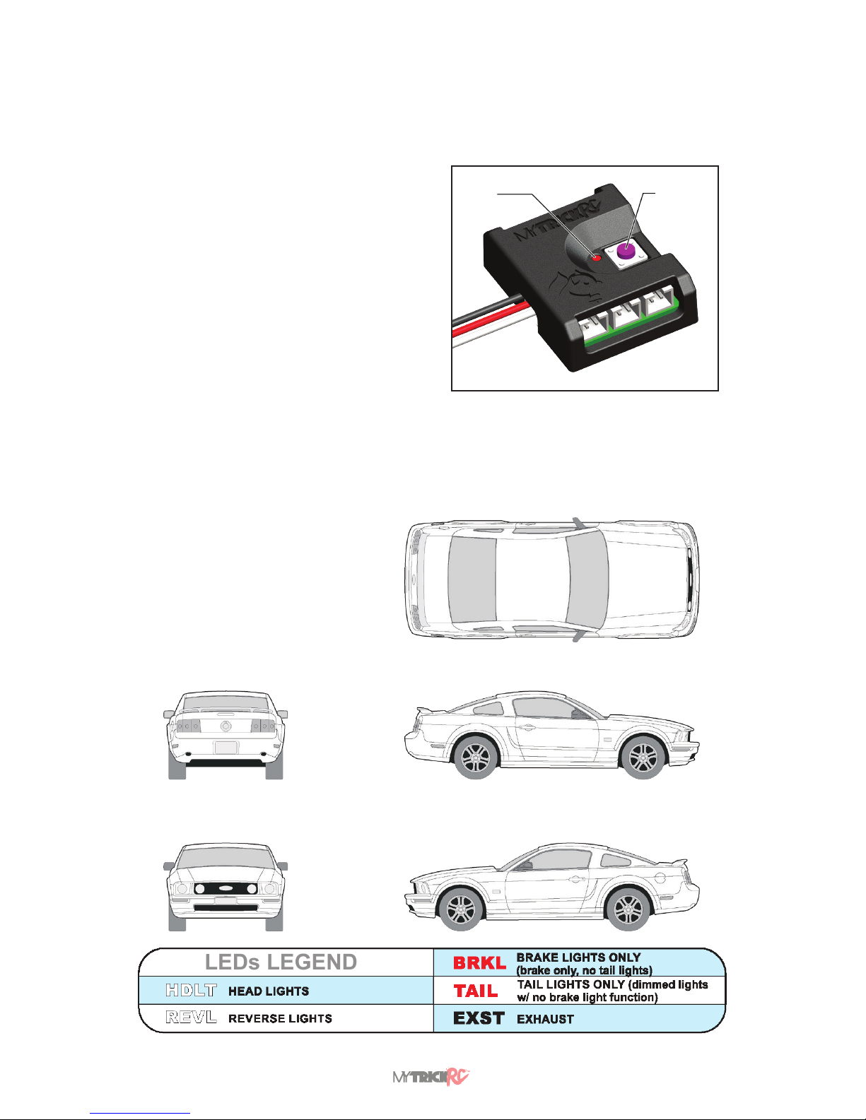
FEATURES & FUNCTIONS
POWER CONNECTIONS & SETTINGS
LEDs LEGEND
USE THIS DIAGRAM TO
ASSIST IN THE LAYOUT
OF YOUR LIGHTING AND
FOR ANY NOTES.
MODE LED
When power is applied to the SQ-1, the Power LED will
blink. The number of LED blinks indicates the mode that
the controller is set to. If you’re in MODE 1 the LED will blink
one time then stay on steady. In MODE 2, the LED will blink
twice, MODE 3, three times, and so on.
MODE Button
To change the MODE, simply press the MODE Button.
NOTES:
• If there is no Power LED, then the controller may be set
to MODE 0 ALL OFF and you should switch to a dierent
mode.
• When SQ-1’s power is restarted, it will remember the
MODE it was last set to.
• If you plug the SQ-1’s power cable backwards into the
receiver or 9V Battery, no damage will occur but the
controller won’t behave correctly. To x, just plug in
correctly.
• You can splice (cut and solder) up to four LEDs into one
SQ-1 output port. Splicing does void the warranty of the
LEDs, but this feature oers more options for your RC
vehicle.
• If you wish to do this then follow these simple guidelines:
• Solder all LEDs in parallel.
• All LEDs in the cable must be the same color.
• Don’t splice more than four LEDs into a single port.
POWER & MODE
LED
MODE
BUTTON
Page 5

Squirrel Rev C5
BLINK MODES
Connections for All LEDs OFF
MODE 0 ALL OFF
CONNECTIONS FOR VEHICLE RECEIVER POWER
Connect to
Motor
NORMAL BRAKE REVERSE BACKFIRE HAZARD
HEADLIGHT A OFF OFF OFF OFF OFF
HEADLIGHT B OFF OFF OFF OFF OFF
RUNNING C OFF OFF OFF OFF OFF
REVERSE D OFF OFF OFF OFF OFF
TAIL/BRAKE E OFF OFF OFF OFF OFF
BACKFIRE F OFF OFF OFF OFF OFF
MODE 0
PORT
NORMAL BRAKE REVERSE BACKFIRE HAZARD
HEADLIGHT A OFF OFF OFF OFF OFF
HEADLIGHT B OFF OFF OFF OFF OFF
RUNNING C OFF OFF OFF OFF OFF
REVERSE D OFF OFF OFF OFF OFF
TAIL/BRAKE E OFF OFF OFF OFF OFF
BACKFIRE F OFF OFF OFF OFF OFF
MODE 0
PORT
CONNECTIONS FOR 9V BATTERY POWER
A B C
D E F
A B C
D E F
Page 6

www.MyTrickRC.com 6
Connections for All LEDs ON
(LEDs on steady at full brightness)
NOTE
If the SQ-1 is powered o the receiver and MODE 1 is not turning on, then toggle the 3rd channel on transmitter.
MODE 1 ALL ON
Default Mode ON/OFF Switchable
NORMAL BRAKE REVERSE BACKFIRE HAZARD
HEADLIGHT A OFF OFF OFF OFF OFF
HEADLIGHT B OFF OFF OFF OFF OFF
RUNNING C OFF OFF OFF OFF OFF
REVERSE D OFF OFF OFF OFF OFF
TAIL/BRAKE E OFF OFF OFF OFF OFF
BACKFIRE F OFF OFF OFF OFF OFF
NORMAL BRAKE REVERSE BACKFIRE HAZARD
HEADLIGHT A BRIGHT BRIGHT BRIGHT BRIGHT BRIGHT
HEADLIGHT B BRIGHT BRIGHT BRIGHT BRIGHT BRIGHT
RUNNING C BRIGHT BRIGHT BRIGHT BRIGHT BRIGHT
REVERSE D BRIGHT BRIGHT BRIGHT BRIGHT BRIGHT
TAIL/BRAKE E BRIGHT BRIGHT BRIGHT BRIGHT BRIGHT
BACKFIRE F BRIGHT BRIGHT BRIGHT BRIGHT BRIGHT
MODE 0
PORT
MODE 1
PORT
ALL LIGHTS SWITCHABLE FROM 3RD CHANNEL ON RECEIVER
CONNECTIONS FOR 9V BATTERY POWER
A B C
D E F
CONNECTIONS FOR VEHICLE RECEIVER POWER
For remote ON/OFF
control connect to
switchable channel on
receiver (AUX channel)
NO CONNECT
A B C
D E F
NORMAL BRAKE REVERSE BACKFIRE HAZARD
HEADLIGHT A OFF OFF OFF OFF OFF
HEADLIGHT B OFF OFF OFF OFF OFF
RUNNING C OFF OFF OFF OFF OFF
REVERSE D OFF OFF OFF OFF OFF
TAIL/BRAKE E OFF OFF OFF OFF OFF
BACKFIRE F OFF OFF OFF OFF OFF
NORMAL BRAKE REVERSE BACKFIRE HAZARD
HEADLIGHT A BRIGHT BRIGHT BRIGHT BRIGHT BRIGHT
HEADLIGHT B BRIGHT BRIGHT BRIGHT BRIGHT BRIGHT
RUNNING C BRIGHT BRIGHT BRIGHT BRIGHT BRIGHT
REVERSE D BRIGHT BRIGHT BRIGHT BRIGHT BRIGHT
TAIL/BRAKE E BRIGHT BRIGHT BRIGHT BRIGHT BRIGHT
BACKFIRE F BRIGHT BRIGHT BRIGHT BRIGHT BRIGHT
MODE 0
PORT
MODE 1
PORT
Page 7

Squirrel Rev C7
MODE 2 DIM HEADLIGHT w/ DUAL DIM TAIL/BRAKE LIGHT
With Backre
After 15 secs of inactivity
• ports B, C, and D switch to HAZARD LIGHTS,
• ports E and F OFF until you start driving again.
NORMAL BRAKE REVERSE BACKFIRE HAZARD
HEADLIGHT A OFF OFF OFF OFF OFF
HEADLIGHT B OFF OFF OFF OFF OFF
RUNNING C OFF OFF OFF OFF OFF
REVERSE D OFF OFF OFF OFF OFF
TAIL/BRAKE E OFF OFF OFF OFF OFF
BACKFIRE F OFF OFF OFF OFF OFF
NORMAL BRAKE REVERSE BACKFIRE HAZARD
HEADLIGHT A BRIGHT BRIGHT BRIGHT BRIGHT BRIGHT
HEADLIGHT B BRIGHT BRIGHT BRIGHT BRIGHT BRIGHT
RUNNING C BRIGHT BRIGHT BRIGHT BRIGHT BRIGHT
REVERSE D BRIGHT BRIGHT BRIGHT BRIGHT BRIGHT
TAIL/BRAKE E BRIGHT BRIGHT BRIGHT BRIGHT BRIGHT
BACKFIRE F BRIGHT BRIGHT BRIGHT BRIGHT BRIGHT
NORMAL BRAKE REVERSE BACKFIRE HAZARD
HEADLIGHT A DIM DIM DIM DIM OFF
HEADLIGHT B DIM DIM DIM DIM OFF
RUNNING C DIM DIM DIM DIM FLASH
TAIL/BRAKE D DIM BRIGHT DIM DIM FLASH
TAIL/BRAKE E DIM BRIGHT DIM DIM FLASH
BACKFIRE F OFF OFF OFF FLASH OFF
MODE 0
PORT
MODE 1
PORT
MODE 2
ALL LIGHTS SWITCHABLE FROM 3RD CHANNEL ON RECEIVER
PORT
CONNECTIONS FOR VEHICLE RECEIVER POWER
Connect to
vehicle radio
(Motor channel)
Connect to
Motor
A B C
D E F
CONNECTIONS FOR 9V BATTERY POWER
A B C
D E F
NORMAL BRAKE REVERSE BACKFIRE HAZARD
HEADLIGHT A OFF OFF OFF OFF OFF
HEADLIGHT B OFF OFF OFF OFF OFF
RUNNING C OFF OFF OFF OFF OFF
REVERSE D OFF OFF OFF OFF OFF
TAIL/BRAKE E OFF OFF OFF OFF OFF
BACKFIRE F OFF OFF OFF OFF OFF
NORMAL BRAKE REVERSE BACKFIRE HAZARD
HEADLIGHT A BRIGHT BRIGHT BRIGHT BRIGHT BRIGHT
HEADLIGHT B BRIGHT BRIGHT BRIGHT BRIGHT BRIGHT
RUNNING C BRIGHT BRIGHT BRIGHT BRIGHT BRIGHT
REVERSE D BRIGHT BRIGHT BRIGHT BRIGHT BRIGHT
TAIL/BRAKE E BRIGHT BRIGHT BRIGHT BRIGHT BRIGHT
BACKFIRE F BRIGHT BRIGHT BRIGHT BRIGHT BRIGHT
NORMAL BRAKE REVERSE BACKFIRE HAZARD
HEADLIGHT A DIM DIM DIM DIM DIM
HEADLIGHT B DIM DIM DIM DIM DIM
RUNNING C DIM DIM DIM DIM DIM
TAIL/BRAKE D DIM DIM DIM DIM DIM
TAIL/BRAKE E DIM DIM DIM DIM DIM
BACKFIRE F OFF OFF OFF OFF OFF
PORT
MODE 0
PORT
MODE 1
PORT
MODE 2
Page 8

www.MyTrickRC.com 8
MODE 3 DIM HEADLIGHT w/ Tail/Brake, Reverse, and Backre
After 15 secs of inactivity
• ports B, C, and D switch to HAZARD LIGHTS,
• ports E and F OFF until you start driving again.
NORMAL BRAKE REVERSE BACKFIRE HAZARD
HEADLIGHT A OFF OFF OFF OFF OFF
HEADLIGHT B OFF OFF OFF OFF OFF
RUNNING C OFF OFF OFF OFF OFF
REVERSE D OFF OFF OFF OFF OFF
TAIL/BRAKE E OFF OFF OFF OFF OFF
BACKFIRE F OFF OFF OFF OFF OFF
NORMAL BRAKE REVERSE BACKFIRE HAZARD
HEADLIGHT A BRIGHT BRIGHT BRIGHT BRIGHT BRIGHT
HEADLIGHT B BRIGHT BRIGHT BRIGHT BRIGHT BRIGHT
RUNNING C BRIGHT BRIGHT BRIGHT BRIGHT BRIGHT
REVERSE D BRIGHT BRIGHT BRIGHT BRIGHT BRIGHT
TAIL/BRAKE E BRIGHT BRIGHT BRIGHT BRIGHT BRIGHT
BACKFIRE F BRIGHT BRIGHT BRIGHT BRIGHT BRIGHT
NORMAL BRAKE REVERSE BACKFIRE HAZARD
HEADLIGHT A DIM DIM DIM DIM OFF
HEADLIGHT B DIM DIM DIM DIM OFF
RUNNING C DIM DIM DIM DIM FLASH
TAIL/BRAKE D DIM BRIGHT DIM DIM FLASH
TAIL/BRAKE E DIM BRIGHT DIM DIM FLASH
BACKFIRE F OFF OFF OFF FLASH OFF
NORMAL BRAKE REVERSE BACKFIRE HAZARD
HEADLIGHT A DIM DIM DIM DIM OFF
HEADLIGHT B DIM DIM DIM DIM OFF
RUNNING C DIM DIM DIM DIM FLASH
REVERSE D OFF OFF BRIGHT OFF OFF
TAIL/BRAKE E DIM BRIGHT DIM DIM FLASH
BACKFIRE F OFF OFF OFF FLASH OFF
MODE 0
PORT
MODE 1
PORT
MODE 2
ALL LIGHTS SWITCHABLE FROM 3RD CHANNEL ON RECEIVER
MODE 3
PORT
PORT
CONNECTIONS FOR 9V BATTERY POWER
A B C
D E F
CONNECTIONS FOR VEHICLE RECEIVER POWER
Connect to
vehicle radio
(Motor channel)
Connect to
Motor
A B C
D E F
NORMAL BRAKE REVERSE BACKFIRE HAZARD
HEADLIGHT A OFF OFF OFF OFF OFF
HEADLIGHT B OFF OFF OFF OFF OFF
RUNNING C OFF OFF OFF OFF OFF
REVERSE D OFF OFF OFF OFF OFF
TAIL/BRAKE E OFF OFF OFF OFF OFF
BACKFIRE F OFF OFF OFF OFF OFF
NORMAL BRAKE REVERSE BACKFIRE HAZARD
HEADLIGHT A BRIGHT BRIGHT BRIGHT BRIGHT BRIGHT
HEADLIGHT B BRIGHT BRIGHT BRIGHT BRIGHT BRIGHT
RUNNING C BRIGHT BRIGHT BRIGHT BRIGHT BRIGHT
REVERSE D BRIGHT BRIGHT BRIGHT BRIGHT BRIGHT
TAIL/BRAKE E BRIGHT BRIGHT BRIGHT BRIGHT BRIGHT
BACKFIRE F BRIGHT BRIGHT BRIGHT BRIGHT BRIGHT
NORMAL BRAKE REVERSE BACKFIRE HAZARD
HEADLIGHT A DIM DIM DIM DIM DIM
HEADLIGHT B DIM DIM DIM DIM DIM
RUNNING C DIM DIM DIM DIM DIM
TAIL/BRAKE D DIM DIM DIM DIM DIM
TAIL/BRAKE E DIM DIM DIM DIM DIM
BACKFIRE F OFF OFF OFF OFF OFF
NORMAL BRAKE REVERSE BACKFIRE HAZARD
HEADLIGHT A DIM DIM DIM DIM DIM
HEADLIGHT B DIM DIM DIM DIM DIM
RUNNING C DIM DIM DIM DIM DIM
REVERSE D OFF OFF OFF OFF OFF
TAIL/BRAKE E DIM DIM DIM DIM DIM
BACKFIRE F OFF OFF OFF OFF OFF
MODE 3
PORT
PORT
MODE 0
PORT
MODE 1
PORT
MODE 2
Page 9

Squirrel Rev C9
MODE 4 FULL BRIGHT w/ Tail/Brake, Reverse, and Backre
After 15 secs of inactivity
• ports B, C, and D switch to HAZARD LIGHTS,
• ports E and F OFF until you start driving again.
NORMAL BRAKE REVERSE BACKFIRE HAZARD
HEADLIGHT A OFF OFF OFF OFF OFF
HEADLIGHT B OFF OFF OFF OFF OFF
RUNNING C OFF OFF OFF OFF OFF
REVERSE D OFF OFF OFF OFF OFF
TAIL/BRAKE E OFF OFF OFF OFF OFF
BACKFIRE F OFF OFF OFF OFF OFF
NORMAL BRAKE REVERSE BACKFIRE HAZARD
HEADLIGHT A BRIGHT BRIGHT BRIGHT BRIGHT BRIGHT
HEADLIGHT B BRIGHT BRIGHT BRIGHT BRIGHT BRIGHT
RUNNING C BRIGHT BRIGHT BRIGHT BRIGHT BRIGHT
REVERSE D BRIGHT BRIGHT BRIGHT BRIGHT BRIGHT
TAIL/BRAKE E BRIGHT BRIGHT BRIGHT BRIGHT BRIGHT
BACKFIRE F BRIGHT BRIGHT BRIGHT BRIGHT BRIGHT
NORMAL BRAKE REVERSE BACKFIRE HAZARD
HEADLIGHT A DIM DIM DIM DIM OFF
HEADLIGHT B DIM DIM DIM DIM OFF
RUNNING C DIM DIM DIM DIM FLASH
TAIL/BRAKE D DIM BRIGHT DIM DIM FLASH
TAIL/BRAKE E DIM BRIGHT DIM DIM FLASH
BACKFIRE F OFF OFF OFF FLASH OFF
NORMAL BRAKE REVERSE BACKFIRE HAZARD
HEADLIGHT A DIM DIM DIM DIM OFF
HEADLIGHT B DIM DIM DIM DIM OFF
RUNNING C DIM DIM DIM DIM FLASH
REVERSE D OFF OFF BRIGHT OFF OFF
TAIL/BRAKE E DIM BRIGHT DIM DIM FLASH
BACKFIRE F OFF OFF OFF FLASH OFF
NORMAL BRAKE REVERSE BACKFIRE HAZARD
HEADLIGHT A BRIGHT BRIGHT BRIGHT BRIGHT OFF
HEADLIGHT B BRIGHT BRIGHT BRIGHT BRIGHT OFF
RUNNING C DIM DIM DIM DIM FLASH
REVERSE D OFF OFF BRIGHT OFF OFF
TAIL/BRAKE E DIM BRIGHT DIM DIM FLASH
BACKFIRE F OFF OFF OFF FLASH OFF
MODE 0
PORT
MODE 1
PORT
MODE 2
ALL LIGHTS SWITCHABLE FROM 3RD CHANNEL ON RECEIVER
MODE 3
PORT
MODE 4
PORT
PORT
CONNECTIONS FOR VEHICLE RECEIVER POWER
Connect to
vehicle radio
(Motor channel)
Connect to
Motor
A B C
D E F
NORMAL BRAKE REVERSE BACKFIRE HAZARD
HEADLIGHT A OFF OFF OFF OFF OFF
HEADLIGHT B OFF OFF OFF OFF OFF
RUNNING C OFF OFF OFF OFF OFF
REVERSE D OFF OFF OFF OFF OFF
TAIL/BRAKE E OFF OFF OFF OFF OFF
BACKFIRE F OFF OFF OFF OFF OFF
NORMAL BRAKE REVERSE BACKFIRE HAZARD
HEADLIGHT A BRIGHT BRIGHT BRIGHT BRIGHT BRIGHT
HEADLIGHT B BRIGHT BRIGHT BRIGHT BRIGHT BRIGHT
RUNNING C BRIGHT BRIGHT BRIGHT BRIGHT BRIGHT
REVERSE D BRIGHT BRIGHT BRIGHT BRIGHT BRIGHT
TAIL/BRAKE E BRIGHT BRIGHT BRIGHT BRIGHT BRIGHT
BACKFIRE F BRIGHT BRIGHT BRIGHT BRIGHT BRIGHT
NORMAL BRAKE REVERSE BACKFIRE HAZARD
HEADLIGHT A DIM DIM DIM DIM DIM
HEADLIGHT B DIM DIM DIM DIM DIM
RUNNING C DIM DIM DIM DIM DIM
TAIL/BRAKE D DIM DIM DIM DIM DIM
TAIL/BRAKE E DIM DIM DIM DIM DIM
BACKFIRE F OFF OFF OFF OFF OFF
NORMAL BRAKE REVERSE BACKFIRE HAZARD
HEADLIGHT A DIM DIM DIM DIM DIM
HEADLIGHT B DIM DIM DIM DIM DIM
RUNNING C DIM DIM DIM DIM DIM
REVERSE D OFF OFF OFF OFF OFF
TAIL/BRAKE E DIM DIM DIM DIM DIM
BACKFIRE F OFF OFF OFF OFF OFF
NORMAL BRAKE REVERSE BACKFIRE HAZARD
HEADLIGHT A BRIGHT BRIGHT BRIGHT BRIGHT BRIGHT
HEADLIGHT B BRIGHT BRIGHT BRIGHT BRIGHT BRIGHT
RUNNING C DIM DIM DIM DIM DIM
REVERSE D OFF OFF OFF OFF OFF
TAIL/BRAKE E DIM DIM DIM DIM DIM
BACKFIRE F OFF OFF OFF OFF OFF
MODE 3
PORT
MODE 4
PORT
PORT
MODE 0
PORT
MODE 1
PORT
MODE 2
CONNECTIONS FOR 9V BATTERY POWER
A B C
D E F
Page 10

www.MyTrickRC.com 10
MODE 5 RANDOM FLASH
With Backre
After 15 secs of inactivity
• ports B, C, and D switch to HAZARD LIGHTS,
• ports E and F OFF until you start driving again.
NORMAL BRAKE REVERSE BACKFIRE HAZARD
HEADLIGHT A RANDOM RANDOM RANDOM RANDOM RANDOM
HEADLIGHT B RANDOM RANDOM RANDOM RANDOM RANDOM
RUNNING C RANDOM RANDOM RANDOM RANDOM RANDOM
REVERSE D RANDOM RANDOM RANDOM RANDOM RANDOM
TAIL/BRAKE E RANDOM RANDOM RANDOM RANDOM RANDOM
BACKFIRE F OFF OFF OFF OFF OFF
MODE 5
PORT
CONNECTIONS FOR 9V BATTERY POWER
A B C
D E F
NORMAL BRAKE REVERSE BACKFIRE HAZARD
HEADLIGHT A RANDOM RANDOM RANDOM RANDOM RANDOM
HEADLIGHT B RANDOM RANDOM RANDOM RANDOM RANDOM
RUNNING C RANDOM RANDOM RANDOM RANDOM RANDOM
REVERSE D RANDOM RANDOM RANDOM RANDOM RANDOM
TAIL/BRAKE E RANDOM RANDOM RANDOM RANDOM RANDOM
BACKFIRE F OFF OFF OFF OFF OFF
MODE 5
PORT
CONNECTIONS FOR VEHICLE RECEIVER POWER
Connect to
vehicle radio
(Motor channel)
Connect to
Motor
A B C
D E F
Page 11

Squirrel Rev C11
MODE 6 STROBE HEADLIGHTS
With Backre
After 15 secs of inactivity
• ports B, C, and D switch to HAZARD LIGHTS,
• ports E and F OFF until you start driving again.
A B C
D E F
CONNECTIONS FOR 9V BATTERY POWER
NORMAL BRAKE REVERSE BACKFIRE HAZARD
HEADLIGHT A RANDOM RANDOM RANDOM RANDOM RANDOM
HEADLIGHT B RANDOM RANDOM RANDOM RANDOM RANDOM
RUNNING C RANDOM RANDOM RANDOM RANDOM RANDOM
REVERSE D RANDOM RANDOM RANDOM RANDOM RANDOM
TAIL/BRAKE E RANDOM RANDOM RANDOM RANDOM RANDOM
BACKFIRE F OFF OFF OFF OFF OFF
NORMAL BRAKE REVERSE BACKFIRE HAZARD
HEADLIGHT A STROBE STROBE STROBE STROBE OFF
HEADLIGHT B STROBE STROBE STROBE STROBE OFF
RUNNING C DIM DIM DIM DIM FLASH
REVERSE D OFF OFF BRIGHT OFF OFF
TAIL/BRAKE E DIM BRIGHT DIM DIM FLASH
BACKFIRE F OFF OFF OFF FLASH OFF
MODE 6
PORT
MODE 5
PORT
NORMAL BRAKE REVERSE BACKFIRE HAZARD
HEADLIGHT A RANDOM RANDOM RANDOM RANDOM RANDOM
HEADLIGHT B RANDOM RANDOM RANDOM RANDOM RANDOM
RUNNING C RANDOM RANDOM RANDOM RANDOM RANDOM
REVERSE D RANDOM RANDOM RANDOM RANDOM RANDOM
TAIL/BRAKE E RANDOM RANDOM RANDOM RANDOM RANDOM
BACKFIRE F OFF OFF OFF OFF OFF
NORMAL BRAKE REVERSE BACKFIRE HAZARD
HEADLIGHT A STROBE STROBE STROBE STROBE STROBE
HEADLIGHT B STROBE STROBE STROBE STROBE STROBE
RUNNING C DIM DIM DIM DIM DIM
REVERSE D OFF OFF OFF OFF OFF
TAIL/BRAKE E DIM DIM DIM DIM DIM
BACKFIRE F OFF OFF OFF OFF OFF
MODE 6
PORT
MODE 5
PORT
CONNECTIONS FOR VEHICLE RECEIVER POWER
Connect to
vehicle radio
(Motor channel)
Connect to
Motor
A B C
D E F
Page 12

 Loading...