

Page 1
W W W . A T T A C K . S K
THE WOOD GASIFYING BOILER
ATTACK® SLX
PROFI / LAMBDA TOUCH
INSTRUCTIONS FOR USE
Page 2

Page 3

3
CONTENT
1INTRODUCTION ................................................................................................................................................... 5
1.1GENERAL DESCRIPTION ............................................................................................................................ 5
1.2DESCRIPTION OF MARKINGS OF THE ATTACK SLX BOILERS ........................................................ 6
1.3SAFETY ............................................................................................................................................................ 6
1.4IMPORTANT INFORMATION .................................................................................................................... 6
1.5TECHNICAL DESCRIPTION ........................................................................................................................ 7
1.6FUEL ................................................................................................................................................................. 8
1.6.1WOOD .................................................................................................................................................... 8
1.6.2ALTERNATIVE FUELS.......................................................................................................................... 8
2TECHNICAL PARAMETERS OF ATTACK SLX BOILERS ............................................................................... 9
3DIMENSIONS AND MAIN PARTS OF THE ATTACK® SLX BOILERS ................................................................ 10
4PURPOSE OF USE ............................................................................................................................................. 11
5ASSEMBLY AND INSTALLATION OF THE BOILER ................................................................................... 12
5.1MANIPULATION WITH BOILER ............................................................................................................. 12
5.2GENERAL CONDITIONS OF INSTALLATION ..................................................................................... 12
5.3BOILER PLACING ....................................................................................................................................... 12
5.4CONNECTION OF THE BOILER TO THE HEATING SYSTEM .......................................................... 14
5.4.1USE OF ANTIFREEZE MIXTURE .................................................................................................... 14
5.4.2PROTECTION AGAINST CORROSION ......................................................................................... 14
5.4.3OUTFALL OF THE FLUE OUT OF THE BOILER .......................................................................... 15
5.4.4CONNECTION OF THE BOILER TO THE CHIMNEY.................................................................. 15
5.4.5CONNECTION TO THE ELECTRICITY MAINS ............................................................................ 16
5.4.6OPTION AND THE WAY OF CONNECTION OF THE CONTROL AND SAFETY ELEMENTS ......... 16
5.4.7PROTECTION OF THE BOILER AGAINST OVERHEATING ...................................................... 17
5.4.8CONNECTION TO THE ACCUMULATION TANKS ................................................................... 18
5.4.9SCHEMES OF BOILER CONNECTION TO THE ACCUMULATION TANKS ......................... 19
5.4.10STANDARDLY DELIVERED ACCUMULATION TANKS ATTACK* ......................................... 22
5.5BINDING NORMS FOR DESIGNING AND ASSEMBLY OF THE BOILERS .................................... 23
6BOILER OPERATION ......................................................................................................................................... 24
6.1OPERATING PRESCRIPTIONS ................................................................................................................ 24
6.2HEATING UP, OPERATION AND FUEL REFILLING ........................................................................... 25
6.2.1PROTECTIVE TOOLS FOR WORK WITH THE BOILER .............................................................. 30
6.3CONTROL OF THE ATTACK SLX PROFI BOILER ............................................................................... 30
6.3.1ADVANTAGES OF REGULATOR ................................................................................................... 30
6.3.2BASIC DESCRIPTION OF THE REGULATOR .............................................................................. 31
6.3.3CONNECTION OF THE PROFI PID REGULATOR BY HYDRAULIC SCHEMES ................... 32
6.3.4REGULATOR CONTROL AND OPERATING MODES ............................................................... 37
6.3.5SETTING THE USER PARAMETERS .............................................................................................. 37
6.3.6SETTING THE SERVICE PARAMETERS ........................................................................................ 39
6.3.7DESCRIPTION OF PARAMETERS .................................................................................................. 40
6.3.8ERROR MESSAGES ........................................................................................................................... 43
6.3.9DISASSEMBLY OF THE REGULATOR .......................................................................................... 44
6.3.10TECHNICAL SPECIFICATION OF THE REGULATOR ................................................................ 44
6.3.11SETTING THE AIR FLAPS AND FLUE GAS TEMPERATURE ................................................... 44
6.4ATTACK SLX LAMBDA TOUCH BOILER CONTROL ......................................................................... 46
6.4.1BASIC CONTROL ELEMENTS ........................................................................................................ 46
6.4.2THE REGULATOR WAY OF WORK: .............................................................................................. 47
6.4.3DESCRIPTION OF MAIN CONTROL MODES: ............................................................................ 48
6.4.4STARTING UP THE REGULATOR .................................................................................................. 50
6.5DISPLAYING THE INFORMATION ........................................................................................................ 53
6.5.1SETTING THE PARAMETERS.......................................................................................................... 54
Page 4

4
6.5.2LEVEL OF SETTING THE BASIC PARAMETERS ......................................................................... 55
6.5.3LEVEL OF SETTING THE ADVANCED PARAMETERS .............................................................. 56
6.5.4SPECIFIC SETTINGS ......................................................................................................................... 60
6.5.5CONNECTION TO THE INTERNET ................................................................................................ 61
6.5.6SOFTWARE UPDATE ....................................................................................................................... 62
6.5.7FACTORY SETTINGS AND RESET ................................................................................................. 62
7RISK ANALYSIS .................................................................................................................................................. 63
8BOILER MAINTENANCE .................................................................................................................................. 65
8.1BOILER CLEANING .................................................................................................................................... 66
8.2INSTALLATION AND REPLACING OF FIREPROOF PARTS ............................................................. 67
9TRANSPORT, MANIPULATION AND STORING ......................................................................................... 68
9.1INSTRUCTIONS TO PRODUCT DISPOSAL AFTER TERMINATION OF ITS LIFE-TIME ............. 68
9.2WRAPPING DISPOSAL ............................................................................................................................. 68
9.3ACCESSORIES ............................................................................................................................................ 69
10POSSIBLE FAILURES AND THE WAY OF ITS REMOVAL ......................................................................... 69
11CHARACTERISTIC OF TEMPERATURE SENSORS ..................................................................................... 70
12ELECTRICAL SCHEMES .................................................................................................................................... 71
12.1ATTACK SLX PROFI .................................................................................................................................. 71
12.2ATTACK SLX LAMBDA TOUCH ............................................................................................................. 72
NOTES ............................................................................................................................................................................ 73
Page 5

5
1 INTRODUCTION
Dear customer,
thank you for your trust and purchase of our product – wood gasifying boiler ATTACK SLX. We wish it
serves you reliably for a long time. The reliable and correct function of device is related to its operation and therefore it is necessary to read this user manual. The manual is written with respect to the
correct function of the boiler.
The correct function of the boiler particularly depends on the following:
choice of the correct boiler output and type
perfect commissioning
correct operation
regular professional maintenance
reliable service
1.1 GENERAL DESCRIPTION
Name: Wood gasifying boiler ATTACK SLX 20, 25, 30, 35, 40, 45, 50, 55
In version „PROFI“, „LAMBDA Touch“
Type: ATTACK SLX 20, 25, 30, 35, 40, 45, 50, 55
Max. operation pressure: 250 kPa
Electr. power supply: 230 V/50 Hz/10 A
Elektr. input: 20, 25, 30, 35 SLX – 42 W
40, 45, 50, 55 SLX – 78 W
Fuel: Dry wood with calorific value 15 up to 17 MJ/kg, moisture 12 up to
20 %, diameter 80 up to 150 mm
Nominal output: 20, 25, 30, 35, 40, 45, 50, 55 kW
Gasifying boiler ATTACK SLX is intended for economical and ecological heating of the family
houses, cottages, small plants, workshops and similar objects.
Prescribed fuel for ATTACK SLX is dry wood logs or chopped pieces with length according to the
type of the boiler.
Water temperature in cooling circuit has to be 8–12 °C. Water pressure is fixed: 0,25 MPa min.
and 0,6 MPa max.
ATTACK SLX boilers work in non-condensation operation. Behind the chimney connection work
in overpressure operation.
Level of the acoustic pressure A does not exceed 70 dB (A).
Immediate peak value of the acoustic pressure C does not exceed 63 Pa.
Producer ATTACK, s.r.o. reserves the right of technical changes of products without previous notification.
Page 6
6
1.2 DESCRIPTION OF MARKINGS OF THE ATTACK SLX BOILERS
ATTACK SLX 20
Profi
25
LAMBDA
Touch
30
35
40
45
50
55
Wood gasifying boiler
Boiler output
Version type
1.3 SAFETY
In this manual are used following warning symbols for ilustration of the danger importance and
important safety notifications:
CAUTION!: Immediate danger situation and it could lead to the serious health or property damage if the right steps are not taken. Take the action according to the instruc-
tions!
WARNING: Dangerous situation might occur. It could lead to the serious health or property damage if the right steps are not taken. Work with extreme caution!
NOTICE: Dangerous situation might occur. It could lead to the serious health or property
damage if the right steps are not taken.
1.4 IMPORTANT INFORMATION
Boiler is delivered with documents and components in the feeding chamber, because of that,
please ensure before first heat up, that the feeding chamber is empty.
Assembly, checking heat up and training of the operation is performed by the assembly
technician who is trained by the producer and s(he) also fill protocol about the boiler installation.
During the gasification, tar and condensates (acids) are created in the fuel tray. That is why
the mixing device has to be installed behind the boiler, to ensure the minimum temperature
of the backflow water to the boiler 65 °C. Operation temperature of the water in the boiler
has to be in range of 80–90 °C.
Boiler must not be operated constantly in the output range lower than 50 %.
Ecological operation of the boiler is by the nominal output.
That is why we recommend to install the boiler with accumulation tanks and mixing device,
what ensures 20–30 % fuel saving and longer lifetime of the boiler and chimney with more
comfortable operation.
Page 7
7
We recommend to connect the boiler with accumulation tank with minimum volume of 70 l
to 1 kW boiler output.
Use only dry fuel with 12–20 % moisture (with higher fuel moisture is decreased boiler out-
put and increases its consumption)
Right choice of the boiler size, i.e. its heat output, is very important condition for economical
operation and correct function of the boiler. Boiler has to be chosen according to its nominal
output, which must meet the heat losses of the heated object.
WARNING: Boiler might be used only for intended purpose and only in the way described in this manual.
CAUTION!: After the boiler disconnection from electricity mains during the operation,
burning continues in the sustain mode. Do not open the boiler door until the tempera-
ture drops below 40 °C.
The boiler warranty is not valid, if:
Is not operated with prescribed fuel
In the system is not installed the mixing device ATTACK – OVENTROP, which ensures the
backflow water temperature to the boiler at least 65 °C during the operation
Functional thermostatic valve wont be installed at the aftercooling circuit of the boiler (e.g.
WATTS STS20) and then connected to the source of the cooling water.
Boiler is not installed according to the requirements stated in this manual, e.g. correct di-
mensions of the chimney etc.
Is not sufficiently cleaned according to the instructions given in this manual
This appliance is not intended for use by persons (including children) with physical, sensual or
mental disability or insufficient experience due to which they are not able to use the device in a
safe way without being supervised or instructed about the boiler operation by the person responsible for their safety. Do not to allow children to play with this appliance.
If the power supply cable is damaged, it must be replaced with the correct type of
the cable, which is available by producer or by a service technician!
Be careful during the work with this appliance! Lambda probe works by high temperatures (300 °C) and you might get burned during careless manipulation!
1.5 TECHNICAL DESCRIPTION
Boiler is constructed for wood combustion, based on the gasifying with use of exhaust fan,
which makes forced flow in the boiler and sucks the flue gas out of the boiler. Boiler body is
made as the weld from steel plates of 6 mm thickness. In the upper part of the boiler is feeding
chamber with above-standard volume, equipped with dry sheath technology, which lowers the
condensate creation and prolong lifetime of the boiler. In the bottom part of the feeding chamber is fireproof nozzle with longitudinal hole for crossing the wood gas to the combustion
chamber. Secondary air is brought by the nozzle and after mixing with wood gas creates burning in the combustion chamber. Combustion chamber is also the ashtray, where are collected
wastes after combustion (ash). In the rear part of the boiler body is tubular exchanger equipped
with turbulators, which serves for cleaning the exchanger and increasing the boiler efficiency.
Turbulators might be controlled manually or automatically (using engine) according to the
boiler version PROFI or LAMBDA Touch. In the upper part of the boiler is situated boiler regulation, which controls the wood gasification process and offers all important information about
Page 8
8
the boiler operation. Flue gas suction by the feeding is solved by the exhaust canal in the upper
part of the combustion chamber and leads directly to the chimney – go around the exchanger.
Boiler is designed for long period of combustion (4 up to 8 hrs, depending on the output) and
that is why it needs to be equipped with accumulation tank.
1.6 FUEL
1.6.1 WOOD
In the ATTACK SLX boiler is possible to use soft and hard chopped fuelwood with calorific value
in range of 15 to 17 MJ/kg. Ideal are especially beech, oak, fir, spruce, pine, popolar tree, alder,
willow, birch, ash tree, hornbeam, locust tree, always with moisture in range of 12 up to 20 %.
Suitable diameter of logs is in range of 80 up to 150 mm. Maximal lenght of the logs must not
exceed 680 mm for 20, 25, 30, 35 SLX boilers and 780 mm for 40, 45, 50, 55 SLX boilers to prevent
wood jam in the feeding chamber.
Calorific value of particular types of wood:
Units
Wood Kcal/kg
MJ/kg
kWh/kg
Spruce 3 900 16,25 4,5
Pine 3 800 15,80 4,4
Birch 3 750 15,50 4,3
Oak 3 600 15,10 4,2
Beech 3 450 14,40 4,0
WARNING: Unsuitable moisture or size of the wood might cause lowering or increasing
the output, low or high temperature of the flue gas, excessive condensation, flame loss
of the gasifying process or uncontrollable combustion.
Recommended wood storing and drying:
Hard wood: stored in dry environment for 2 years
Soft wood: stored in dry environment for 1 year
Wood must be secured against rain during storage (drying). You can help to the wood drying
effectiveness by storing the wood with as large as possible spaces between each piece of wood
to let the air flow between them. It is good to store the wood in the environment with air
draught, what ensures faster drying. If possible, store the wood at least 1 day in the warm place
(e.g. boiler room – wood will be preheated and it will lead to the combustion effectiveness) before feeding in the boiler.
1.6.2 ALTERNATIVE FUELS
It is possible to use also wood briquettes with hole, pressed from wood sawdusts without any
additional connective materials. It is necessary to mix wood briquettes with wood in particular
ratio (ratio depends on the size and shape of the briquettes), to prevent clogging of the nozzle
for wood gasifying.
WARNING: Fuels, which are not allowed increase demands on cleaning and lead to the
accumulation of aggressive sedimentation and condensation. In the end, it might lead to
lowered functionality, boiler damage and invalid warranty. Use of unallowed fuels might
lead to incorrect and uncontrollable combustion.
Page 9
9
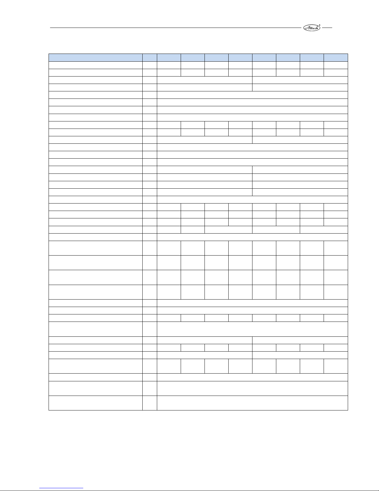
2 TECHNICAL PARAMETERS OF ATTACK SLX BOILERS
Parameter / Boiler type SLX20 SLX25 SLX30 SLX35 SLX40 SLX45 SLX50 SLX55
Nominal output of the boiler kW 20 25 30 35 40 45 50 55
Output range kW 10–20 12,5
–
25
15–30 17,5–35 20–40 22,5–45 25–50 27,5–55
Area of the exchanger m² 2,95 3,32
Volume of the feeding chamber dm³ 200 230
Dimensions of the feeding hole mm 235 × 445
Prescribed chimney draught Pa 23
Prescribed chimney draught mbar 0,23
Max. working overpressure of the water kPa 250
Pressure loss of the water (ΔT 10K) kPa 1,9 2,1 2,4 2,7 3,9 4,5 5,2 6,1
Pressure loss of the water (ΔT 20K) kPa 0,8 0,9 1,2 1,6 1,9 2,1 2,4 3,2
Weight of the boiler kg 570 650
Diameter of the flue gas outlet mm 150
Height of the boiler mm 1 472
Width of the boiler mm 703
Depth of the boiler mm
1 337
1 506
Depth of the feeding chamber mm 690 790
Diameter of the riser pipe "E" "
G 6/4"
G 2"
Diameter of the reverse "F" "
G 6/4"
G 2"
Protection class IP 21
Electrical input at the nominal output W 42 42 42 42 78 78 78 78
Electrical input at the minimal output W 31 31 31 31 52 52 52 52
Electrical input at the standby mode W < 15 < 15 < 15 < 15 < 15 < 15 < 15 < 15
Boiler efficiency % 91,8 91,6 90,3 90,4 90,3
Boiler class — 5
Temperature of the flue gas by the nominal
output
°C 165 170 175 180 165 170 170 180
Temperature of the flue gas by the minimal
output
°C 130 135 140 145 135 140 140 145
Mass flow of the flue gas by the nominal
output
kg/s 0,018 0,02 0,021 0,023 0,027 0,029 0,031 0,033
Mass flow of the flue gas by the minimal
output
kg/s 0,008 0,011 0,014 0,016 0,017 0,021 0,022 0,023
Max. noise level dB 65
Class and type of the fuel — A, Wood pieces with relative moisture of 12 % – max. 20 %, Ø 50–150 mm
Average wood consumption kg/h 5,2 6,5 7,8 9,1 10,4 11,7 13 14,3
Indicative consumption of the wood per
season
— 1 kW = 1 m
3
Max. length of logs mm 650 750
Time of burning by nominal output * h 8 7,2 6,5 5,8 6 5,1 4,6 4
Volume of the water in the boiler l 117 136
Recommended volume of the accumulation
tank
l 1500 2000 2200 2500 3 000 3 200 3 500 4 000
Voltage V/Hz ~230/50
Range of the setting the temperature of the
heating water
°C 65 ÷ 85
Capacity of the contacts of the boiler regulator (PROFI version)
— 2 A/~230 V
*depending on the type of fuel and perfection of the feeding the chamber with wood
Producer ATTACK, s.r.o. reserves the right of technical changes of products without previous notification.
Page 10
10
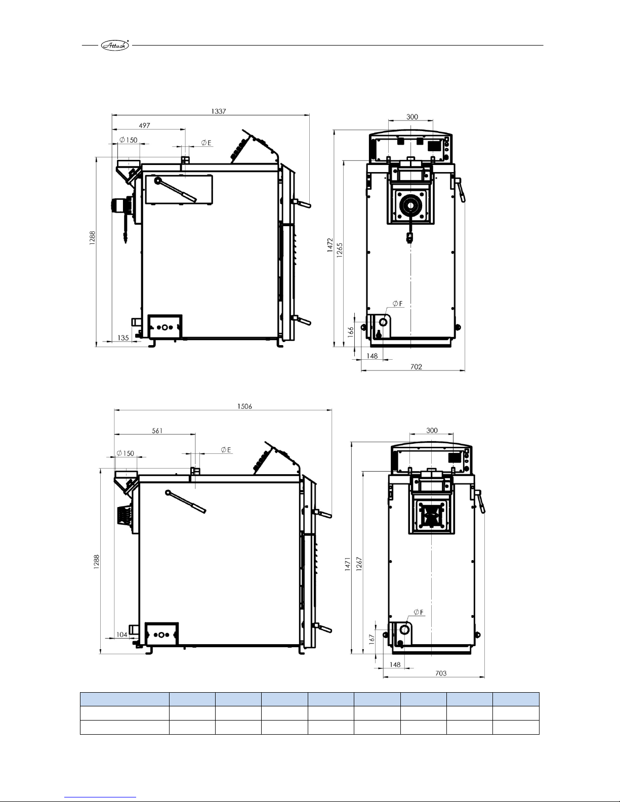
3 DIMENSIONS AND MAIN PARTS OF THE ATTACK® SLX BOILERS
Dimensions of the boilers with output of 20–35 SLX:
Dimensions of the boilers with output of 40–55 SLX:
SLX20 SLX25 SLX30 SLX35 SLX40 SLX45 SLX50 SLX55
Riser pipe – „E“ G 6/4" G 6/4" G 6/4" G 6/4" G2" G2" G2" G2"
Reverse – „F“ G 6/4" G 6/4" G 6/4" G 6/4" G2" G2" G2" G2"
Page 11
11
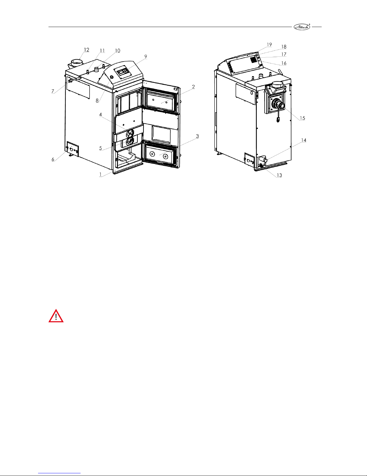
CAPTION:
1. Body of the boiler 6. Cleaning covering 11. Aftercooling circuit 16. Lambda fuse
2. Door of the feeding chamber 7. Lever of turbulators 12. Rotary chimney 17. Emergency thermostat
3. Door of the combustion chamber 8. Manometer 13. Release valve 18. Main switch Lambda
4. Primary air 9. Regulator of the boiler 14. Reverse 19. Control case
5. Secondary air 10. Riser pipe 15. Fan
4 PURPOSE OF USE
Ecological warm water boiler Attack SLX is intended for heating family houses and other similar
objects. Boiler is constructed for combusting wood pieces. It is possible to use any dry wood,
especially wood logs for combustion. Boiler is not intended for combustion of the sawdusts and
small wood wastes. It is possible to combust it only in small quantity (max. 10 %) together with
wood pieces. Massive fuel feeder replaces and removes hardest operation during the wood
preparation and its chopping to smaller pieces.
Placing boilers in dwelling premises (including corridors) is inpermissible!
Page 12

12
5 ASSEMBLY AND INSTALLATION OF THE BOILER
5.1 MANIPULATION WITH BOILER
Boiler is delivered on the pallet. Perform manipulation
with boiler only at the pallet. Put down the boiler form
the pallet immediately at the place of installation. It is
possible to perform this by use of manipulation cart or
by crane and handles, which are welded at the exchanger of the boiler.
Figure 1 Manipulation with boiler with use of the
welded handles
5.2 GENERAL CONDITIONS OF INSTALLATION
Only a person with valid authorization for installation and assembly of the heating technology
devices can install the boiler. The installation requires an appropriate project that is in line with
valid prescriptions. Technician must check the boiler before installing, if data given on the production label are in conformity with data in the project and the documentation attached to the
boiler. The boiler connection must be in line with the valid prescriptions, norms, regulations and
this instruction manual.
WARNING: Producer takes no responsibility for damages caused by wrong connection
or operation!
5.3 BOILER PLACING
Boiler serves for installation and operation in the space with the basic environment (AA5/AB5)
according to STN 33 2000-3.
Boiler room must meet the following requirements:
Boiler is not suitable for use in the potentially explosive environment.
The temperature in the boiler room must not drop below the freezing point.
Boiler does not provide any lighting. Customer must ensure sufficient light source according
to the local norms and regulations.
It is necessary to consult the installation with the producer, if the boiler will be installed at
height above sea level exceeding 1 800 m.
Boiler room must have sufficient ventilation and inlet of the required burning air (minimally
10 cm
2
/kW of the boiler output). Hole for the ventilation should be designed to not let the
outside weather influence its function. (rain, snow, wind)
Page 13

13
During the installation of the boiler must be ensured a safe distance of its surface from the
flammable materials depending on their flammability level:
Materials of flammability level B, C1 a C2 200 mm
Materials of flammability level C3 400 mm
Level of flammability was not proved according to STN 73 0853 400 mm
Examples of building materials division according to the level of flammability:
Level of flammability A not flammable (bricks, breez blocks, ceramic tile, mortar, plaster)
Level of flammability B partly flammable (heraclit, lignos, board made out of basaltic felt, novodur)
Level of flammability C1 hard flammable (broadleaf wood (beech, oak), plywood, werzali, hardened
paper)
Level of flammability C2 intermediate flammable (coniferous wood (pine, spruce), chipboard, so-
lodur)
Level of flammability C3 easily flammable (wood-fibre, polyurethan, PVC, soft foam, polystyrene)
The sealing board or protection covering (on the protected object) must exceed the boiler edge
at least for 300 mm. Also other items from flammable materials must be protected in this way, if
they are placed near the boiler and it is not possible to keep the safe distance.
If the boiler stands on the flammable surface, it must be protected by an inflammable, heat insulating mat, which exceeds the ground plan on the side of the feeding door and ash tray door for
at least 100 mm. All materials of the flammability level A might be used as an inflammable, heat
insulating mat.
Boiler must be placed in a such way, ensuring sufficient space of at least 1 m from the front and
0,5 m from the left (right) and rear side. It is necessary to leave the space of at least 1 m above
the boiler.
This space is necessary for basic operation, maintenance and eventual service of the boiler. It is
not allowed to place the boiler in dwelling premises (including corridors).
WARNING: Items from flammable materials must not be laid on the boiler and in the
distance shorter than the permitted (safe) one. The boiler must be put out of operation,
if there is a danger of fire or explosion during the work (e.g. work with painting materials, glues, etc.).
Page 14
14
5.4 CONNECTION OF THE BOILER TO THE HEATING SYSTEM
Boiler ATTACK® SLX has to be installed in the system, which meets the requirements of the heating water quality as follows:
Country Number of standards Country Number of standards
Slovak republic STN 07 7401:1991 Switzerland SWKI 97-1
Austria ONORM H5195-1 Italy D.P.R. no. 412
Germany VDI 2035
For filling or refilling the water in the system might be used only water which is adapted for values according to STN 07 7401: 1992. Water has to be clear, colourless, without any suspended
substances, oils and chemical agressive additives and cannot be acidic (pH has to be higher than
7,2). Water hardness cannot exceed 1 mmol/l and concentration of Ca²Ѐ 0,3 mmol/l.
NOTICE: The warranty of the boiler is not valid in case of infringement of these conditions!
5.4.1 USE OF ANTIFREEZE MIXTURE
It is not recommended to use antifreeze mixture with not suitable quality for the boiler operation. It is related especially to lowering the heat penetration, big volume expandability, aging,
rubber parts damage. If necessary, use the Alycol Termo (manufacturer Slovnaft Bratislava) antifreezing mixture – according to experiences of producer, there is no risk of lowering the safety of
use and noticeable influencing of the boiler work. If this type of protection against freezing is not
achievable in particular conditions, parameters are not fulfiled or there are some boiler failures
caused by use of other antifreezing mixtures, there is no possibility of warranty.
5.4.2 PROTECTION AGAINST CORROSION
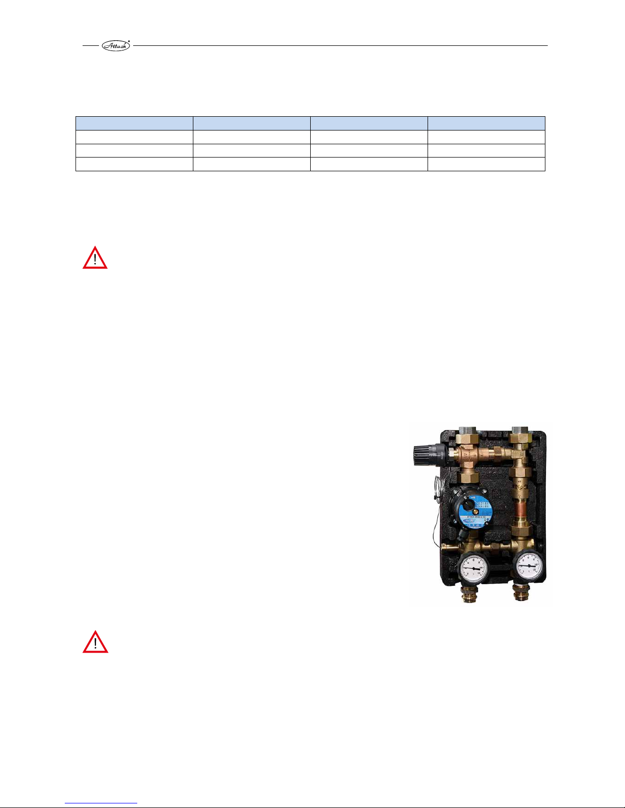
Boiler must be connected with device for controlling the temperature of the boiler reverse. Suitable solution is use of mixing device
ATTACK-OVENTROP (Figure 2), which makes the temperature rise
of the return connection to acceptable level. In this way is boiler
protected against supercooling below 65 °C and creation of the
water steams, acids and tars in the feeding chamber is lowered.
Mixing device ATTACK-OVENTROP allows to set temperature of
return-water in range of ca. 50–70 °C thanks to the thermostatic
head.
Figure 2 Device for protection of the reverse temperature AT-
TACK OVENTROP
NOTICE: If the device against corrosion is not installed in the system or this device does
not work properly, there is a possibility of creation of agressive condensate, which might
lead to the boiler damage. Protection against condensation must be in use during the
boiler operation, otherwise is warranty provided by producer not valid!
Use of the size of ATTACK OVENTROP devices depending on the boiler output:
ATTACK OVENTROP DN25: SLX 20–35 kW
ATTACK OVENTROP DN32: SLX 40–55 kW
Page 15
15
5.4.3 OUTFALL OF THE FLUE OUT OF THE BOILER
Flue has to have outfall to the chimney hole. If it is not possible to connect the boiler to the
chimney hole directly, then the appropriate extension should be as short as possible, of up to 1
m length, without any additional heating area and it must ascend to the chimney. It is good to
insulate the flue, to achieve sufficient flue gas temperature and prevent the chimney condensation. Flues must be mechanically firm (it is recommended to attach the flue to the boiler and bolt
them together) and tight against the flue leakage and cleanable inside. Flues must not lead
through the somebody else's dwelling or commercial premises. The internal diameter of the flue
must not taper in direction to the chimney. It is not eligible to use the elbow connectors. There
must be an „T-shaped“ connection between flue and chimney to let the condensate flow down
to the intended container and not in the boiler.
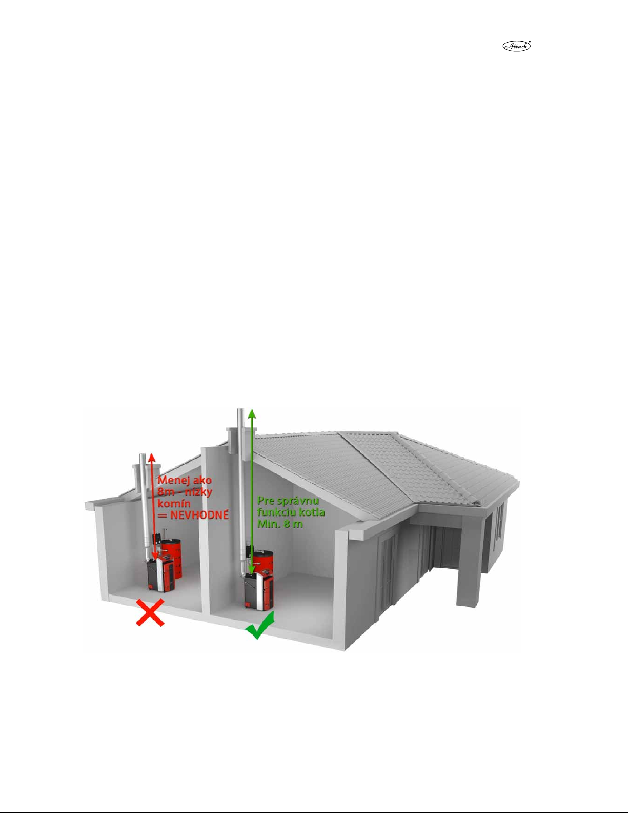
5.4.4 CONNECTION OF THE BOILER TO THE CHIMNEY
Connection of the appliance to the chimney hole must be always done with permission of the
appropriate chimney sweep association. The chimney hole must always generate sufficient
draught and take the flue gas out into the atmosphere under the all operating conditions.
Correct dimensions of the chimney hole are important for correct boiler function, because burning, output and boiler life-time are influenced by the draught. The chimney draught directly depends on its diameter, height and roughness of the internal wall. It is not allowed to connect any
other appliance to the chimney, where is the boiler connected. Diameter of the chimney must
not be smaller than the outlet part of the boiler. Chimney draught must achieve prescribed values. It cannot be too high to not decrease the boiler output and interrupt the burning (flame). If
there is too strong draught, install the throttle flap into the chimney hole between the boiler and
the chimney.
Figure 3 Correct and incorrect parameters of the chimney for connection the SLX boiler
Prescribed values of the chimney diameter and height:
20 × 20 cm min. height 7 m
20 cm min. height 8 m
15 × 15 cm min. height 11 m
16 cm min. height 12 m
Page 16
16
Exact dimensions of the chimney determines STN 73 42 10. Prescribed chimney draught is stated
in Technical parameters. Chimney draught is measured by the devices intended for this operation, minimally 40 cm behind the outfall of the chimney. Draught is measured during the boiler
operation at full output, by the same temperature of flue gas as the set one.
In case, that your chimney does not achieve prescribed parameters of the chimney, it is possible
to install additional fan ATTACK PV150 behind the boiler, which is able to make required parameters of the chimney.
It is necessary to keep in mind by choosing the type of the chimney or during the boiler operation, that stainless insulated chimney (most of the time placed externaly at the sheathing of the
building) has the best qualities of the chimney draught beginning after heat up, because it is
quickly warmed in a whole lenght. Chimney with stainless insertions has worse qualities of the
chimney draugh beginning, because it is warmed slower than insulated chimney. Worst qualities
of the chimney draught beginning has chimney without insertions (e.g. brick or ceramic), because its accumulation to operation temperature takes much longer. So, if the heat up or boiler
start up is problematic, consider recontruction of the chimney and equipping the chimney with
stainless insertions.
5.4.5 CONNECTION TO THE ELECTRICITY MAINS
The boiler is connected to the electricity mains of 230 V/50 Hz/10 A by an electrical cord with
plug. The mains input is type M and by replacing, it must by replaced with the same type by the
service organisation. Appliance must be placed with easy reach of the plug. The boiler must be
connected to the plug circuit with 10 A electrical circuit-breaker (following the STN EN 60 335-1
+ A11:1997).
5.4.6 OPTION AND THE WAY OF CONNECTION OF THE CONTROL AND SAFETY
ELEMENTS
Boiler is delivered with basic equipment, regulation and control elements. It is necessary to purchase other elements, which are not a part of delivery, but have to be installed in the heating
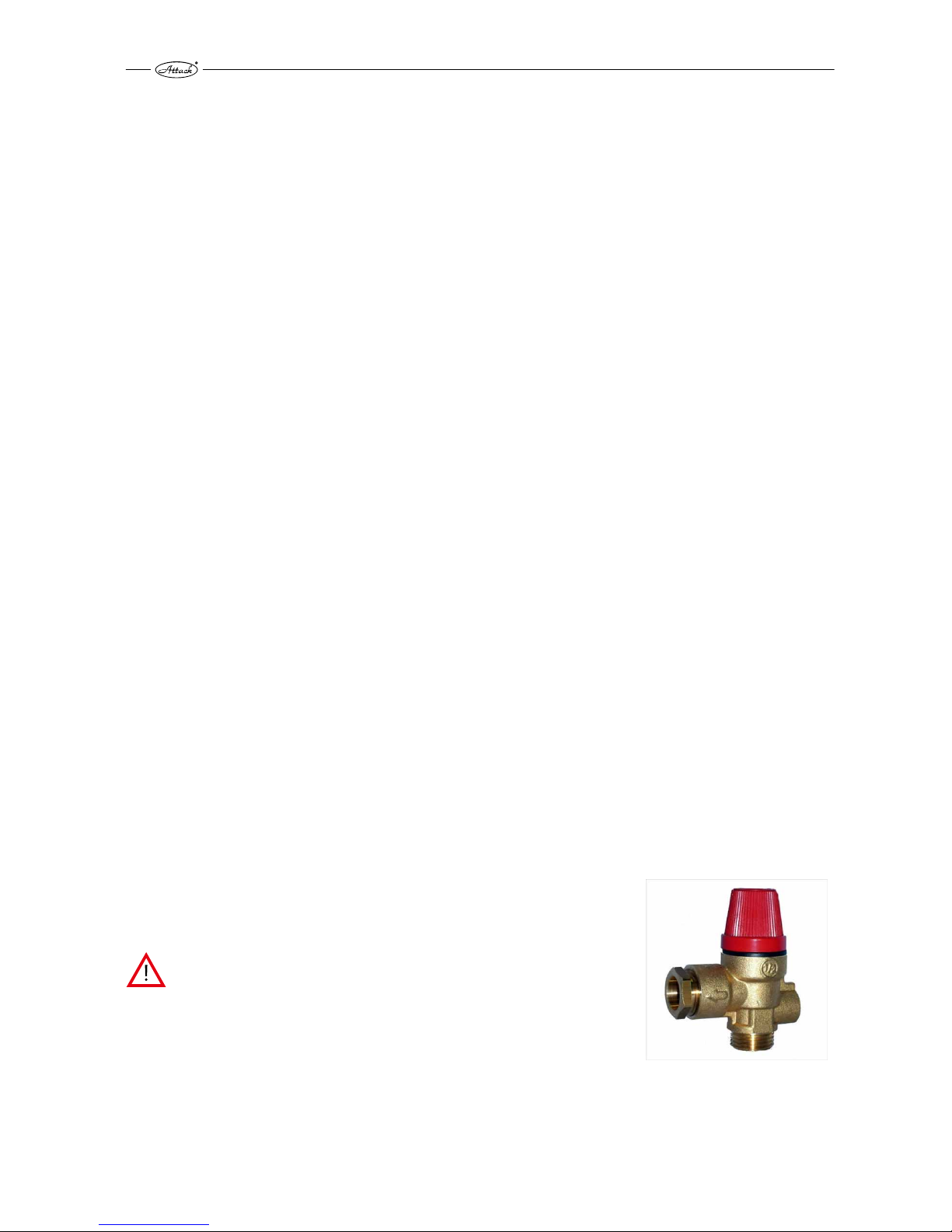
system. It is especially, valve against exceeding permitted pressure (figure 4) in the heating system (we prescribe 2,5 bar), valve of the aftercooling loop of the boiler for draining excess
warmth out of the boiler to the waste and bleeding valve for correct function of the boiler. Expansion tank in the system must have sufficient volume, which is set by the project architect of
the heating system according to valid prescriptions. Electrical installation with sufficient equipment of the boiler has to be performed by the specialist according to valid norms.
CAUTION! Heating system has to be equipped with safety
valve against exceeding pressure in the boiler (2,5 bar). We
recommand to place this valve on the riser pipe of the boiler,
always infront of the closing valve of the boiler (or infornt of
the OVENTROP). If the safety valve would not be func-
tional, excessive pressure would not be able to leak and
boiler might explode!
Figure 4 Safety valve against overpressure
Page 17
17
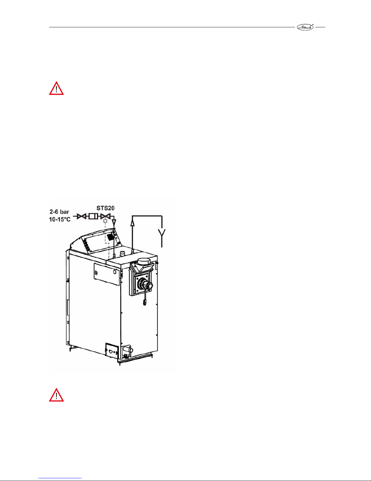
5.4.7 PROTECTION OF THE BOILER AGAINST OVERHEATING
Every gasifying boiler has to be equipped with functional aftercooling circuit. It is possible to
order correct valve for ensuring this function, as accessory. In the figure 5 you can see correct
installation of the aftercooling circuit valve.
CAUTION! Cooling circuit against boiler overheating can not be used according to the
EN 303-5 norm for other purposes as is the boiler protection against overheating.
Valve at the inlet of cooling water to the cooling circuit of the boiler has to be permanently
opened and cooling circuit of the boiler has to be connected to functional distribution of cold
water (e.g. to distribution of cold water of the water network) of 10–15 °C temperature and operating overpressure 2–6 bar, which ensures safety operation even by electricity failure.
Thermostatic valve at the inlet of aftercooling circuit, which has sensor placed at the rear part of
the boiler, protects the boiler against overheating. If the water temperature in the boiler rises
above 95 °C, valve releases water from the water network in the cooling circuit which takes away
excessive warmth. In case of boiler overheating and opening a thermostatic valve, permanent
drain of warmed water from the cooling circuit of the boiler to the waste, has to be ensured.
Functionality of the aftercooling circuit and thermostatic valve might be also checked manually,
with the manual button of the thermostatic valve.
Figure 5 The way of cooling circuit connection
CAUTION! If the circulation of cooling water through the aftercooling circuit would not
be ensured during the opening of thermostatic valve, there is a danger of boiler damage.
In this case is warranty not valid!
Page 18

18
5.4.8 CONNECTION TO THE ACCUMULATION TANKS
System of the connection is based on warming the accumulation tanks, where is the accumulated warmth from accumulation tanks gradually drained according to the requirements of
heated space. During the bioler operation at full output are accumulation tanks warmed at 80–
90 °C. Heating with accumulation tanks in connection with ATTACK SLX boiler brings several
advantages. Main advantages are higher efficiency, lower fuel consumption, prolonged lifetime
of the boiler, more frequent operation, minimal creation of acids and condensates, higher comfort, lower risk of boiler overheating and fuel saving.
Recommended volume of the accumulation tank for ATTACK SLX 25 boiler is 2000 l (for other
outputs see technical parameters). Boiler is able to produce 180 kWh of energy at one loading of
the hard wood to the feeding chamber (it is ca. 7 hours of operation at full 25 kW output). It correspond to charge of 2 000 l accumulation tank from 20 °C to 90 °C if there is no energy offtake
(that is why is necessary to keep in mind by choosing the size of accumulation tank, that boiler
must be operated according to the size of accumulation tank. It means that, if you have 2000 l
tank, load the wood chamber fully. If you have 1000 l tank, load the chamber halfway – if there is
no energy offtake from the accumulation tank). If the accumulation tank is charged (bottom
temperature of the accumulation tank achieves 70 °C) and boiler achieved set boiler temperature, do not load the wood to the boiler. If you would load the wood to the boiler in this state,
wood would not be combusted (boiler has already achieved set temperature and fan has turned
off). It would get dry and condensates would create in the feeding chamber, what lowers boiler
lifetime. It is necessary to fill the wood at the time when the accumulation tank is almost discharged.
Example 1:
Outside temperature of the environment is −5 °C and heat loss of the object is 10 kW by this
temperature. Boiler has 25 kW at the full output operation. Accumulation tank with volume
2000 l is discharged (its upper and bottom temperature is 20 °C). The heating system (to cover
heat loss) drains 10 kW output from accumulation tank and boiler has 25 kW output, accumulation tank will be heated by the output of 15 kW – difference between them. 15 kW output makes
energy of 105 kWh by full loading of the chamber with hard wood and time of the operation ca.
7 hours. Energy of 105 kWh warms accumulation tank from 20 °C to 65 °C. It means, that this is
the safe economic operation without putting the boiler out of operation or draining excessive
warmth to the waste (boiler was cooled by the aftercooling circuit). Boiler is able to cover the
heat loss for up to 15 hours at one wood loading.
Example 2:
Outside temperature of the environment is +3 °C and heat loss of the object is 5 kW by this temperature. Boiler has 25 kW at the full output operation. Accumulation tank with volume 2000 l is
discharged (its upper and bottom temperature is 20 °C). The heating system (to cover heat loss)
drains 5 kW output from accumulation tank and boiler has 25 kW output, accumulation tank will
be heated by the output of 20 kW – difference between them. 20 kW output makes energy of
140 kWh by full loading of the chamber with hard wood and time of the operation ca. 7 hours.
Energy of 140 kWh warms accumulation tank from 20 °C to 80 °C. It means, that this is the safe
economic operation without putting the boiler out of operation or draining excessive warmth to
the waste. If the heat loss of the object would be constant all the time – 5 kW, charged accumulation tank would be able to cover heat loss for about 28 h, what is together with operation time
up to 35 hours without need of wood loading.
That is why it is necessary to keep in mind, that boiler should be loaded only with amount of
wood necessary for charging the accumulation tank, because pointless overheating might lead
to putting the boiler out of the operation or removing excessive warmth to the waste. This is
uneconomical and requires activation of the safety element – aftercooling loop.
Page 19
19
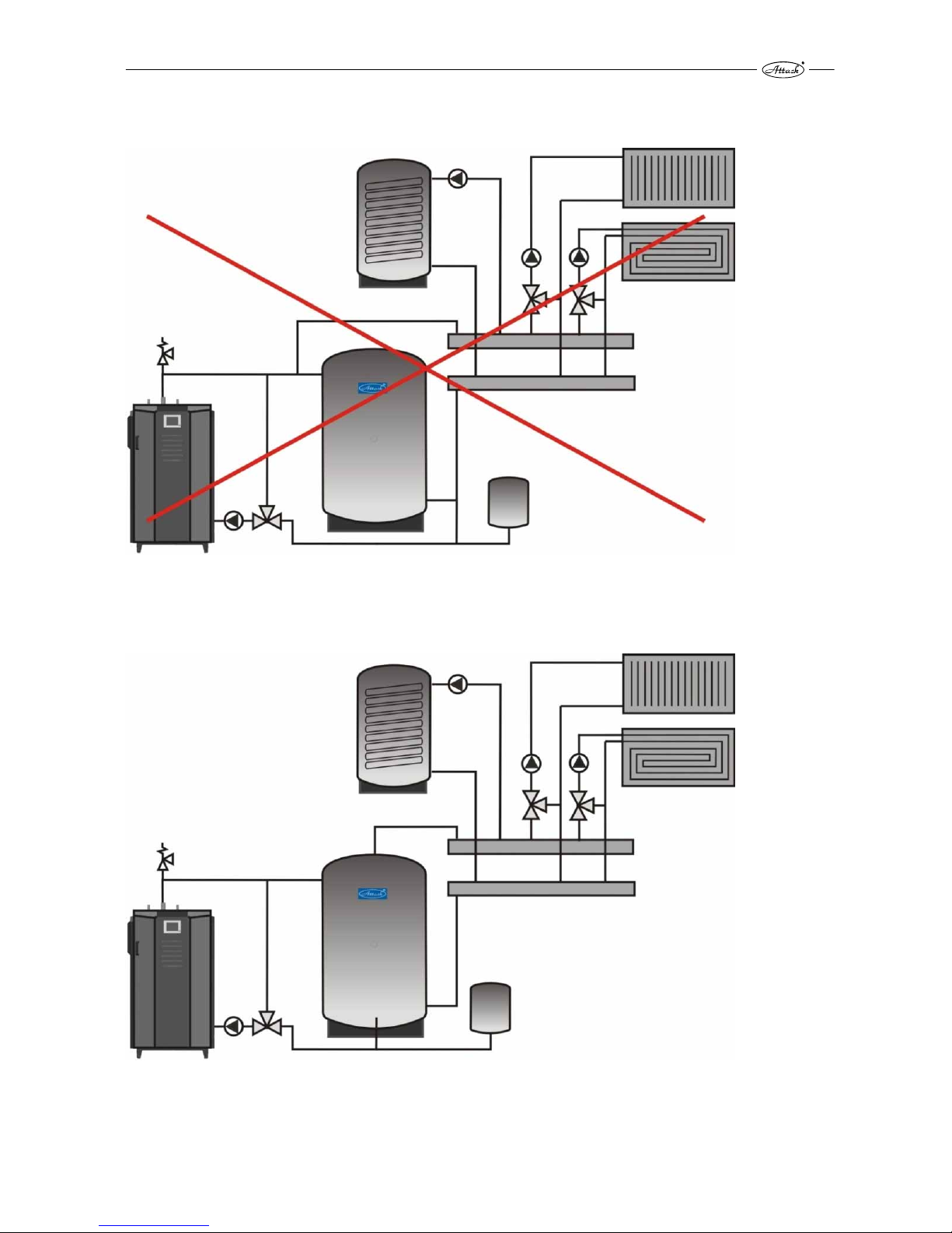
5.4.9 SCHEMES OF BOILER CONNECTION TO THE ACCUMULATION TANKS
Scheme č. 1. – Incorrect connection, where is the heating circuit connected by the T connector
infront of the accumulation tank
Scheme č. 2 – Correct connection of the gasifying boiler with accumulation tank, D.H.W. tank
and mixing heating circuits (radiator and flooring)
Page 20
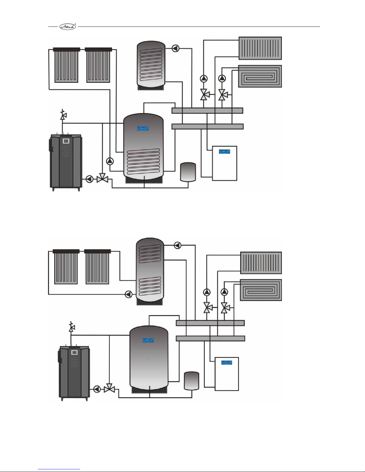
20
Scheme č. 3 – Connection of the gasifying boiler with accumulation tank with spiral for solar
heating, D.H.W. tank, solar panels, mixing heating circuits (radiator and flooring) and automatic
boiler (e.g. gas)
Scheme č. 4 – Connection of the gasifying boiler with accumulation tank, D.H.W. tank with spiral
for solar heating, solar panels, mixing heating circuits (radiator and flooring) and automatic
boiler (e.g. gas)
Page 21
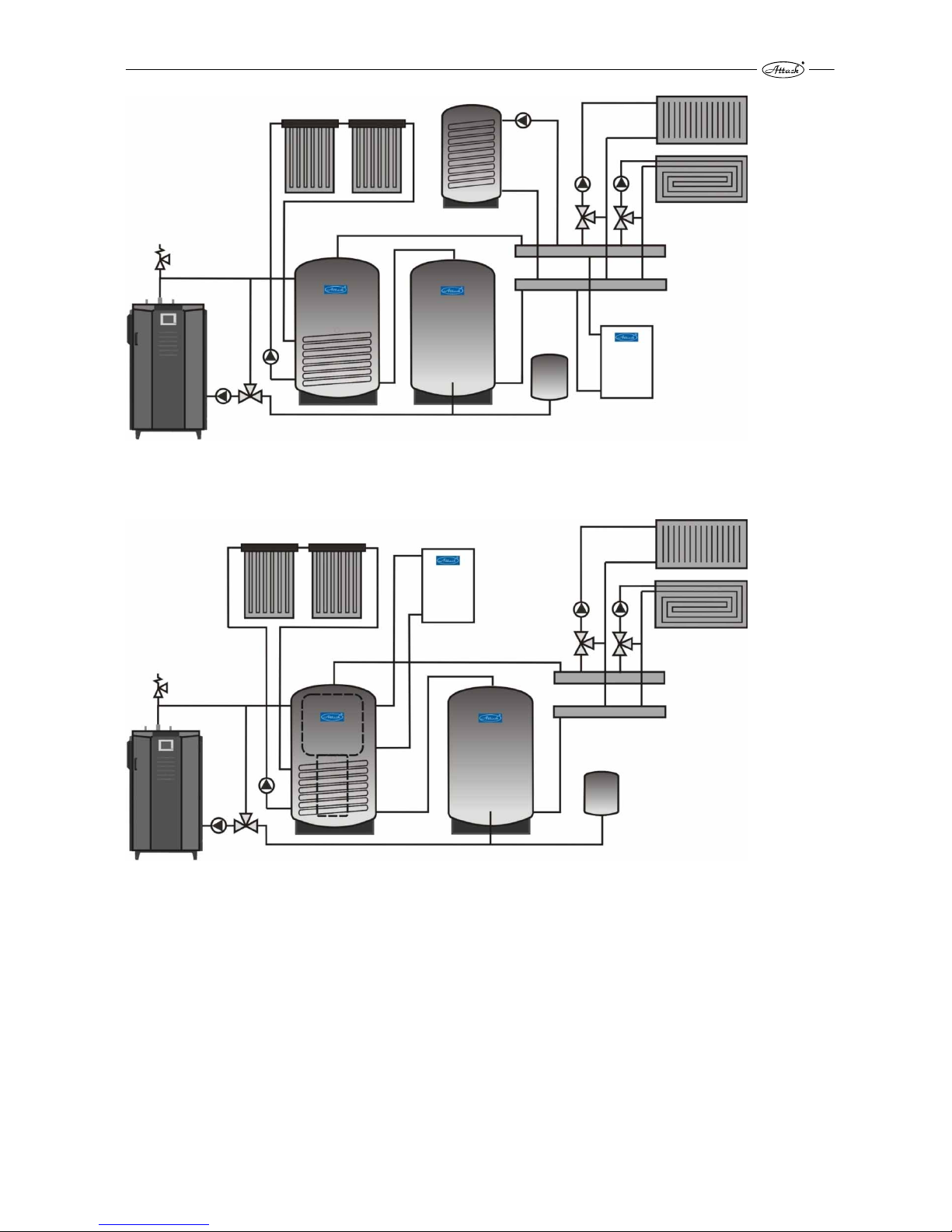
21
Scheme č. 5 – Connection of the gasifying boiler with two accumulation tanks
Scheme č. 6 – Connection of the gasifying boiler with combined accumulation tank
For other ways of connection, please visit web page www.attack.sk, where you can find wide
range of options for connection to the heating circuits.
Page 22
22
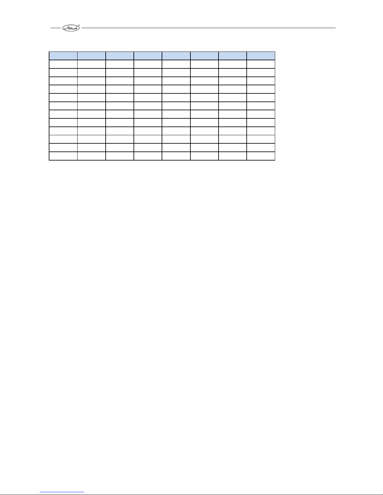
5.4.10 STANDARDLY DELIVERED ACCUMULATION TANKS ATTACK*
AK AS HR HRS TUV
TUVS
S SS
200 200 — — — — — —
300 300 — — — — — —
400 400 — — — — — —
500 500 600 600 500
500
500 500
800 800 800 800 600
600
800 800
1000 1000 1000 1000 800
800
1000 1000
1500 1500 1250 1250 1000
1000
1250 1250
2000 2000 1500 1500 1250
1250
1500 1500
2500 2500 2000 2000 1500
1500
2000 2000
3000 3000 — — 2000
2000
— —
4000 4000 — — — — — —
5000 5000 — — — — — —
AK – standard accumulation tank designed for accumulation of heating water
AS – accumulation tank for accumulating of heating water, equipped with a heating coil for
connection to solar panels
HR – combined accumulation for accumulation of the heating water as well as for preparation of
the D.H.W. by an internal enameled exchanger
HRS – combined accumulation for accumulation of the heating water as well as for preparation
of the D.H.W. by an internal enameled exchanger, equipped with a heating coil for connection to
solar panels
TUV – accumulation tank for accumulation of the heating water as well as for the D.H.W. preparation in a water coil
TUVS – accumulation tank for accumulation of the heating water as well as for the D.H.W. preparation in a water coil, equipped with a heating coil for connection to solar panels
S – accumulation tank with internal disk and stratification pipe (based on the type AK) that allows layering of water as necessary (different water temperature on inputs as well on outputs)
SS – accumulation tank with internal disk and stratification pipe (based on the type AS and S),
equipped with a heating coil for connection to solar panels
* Required volume for required accumulation of energy is possible to cover one or several accumulation tanks. Accumulation tanks can be connected together to create required volume of accumulation water. Therefore, if you decided that your accumulation volume will be 2000 l, you can buy a single accumulation tank of 2000 l or two accumulation tanks with a capacity of 1000 l and connect
them together.
Page 23

23
5.5 BINDING NORMS FOR DESIGNING AND ASSEMBLY OF THE
BOILERS
Boiler installation must be preformed in conformity with following norms:
STN EN 303-5:2012 Heating boilers for solid fuels
STN 73 42 10 Construction of the chimneys and flues
STN 92 0300 Fire safety of the local appliances and heat sources
STN EN 60 335.1 +A11 Safety of the electrical appliances for household
STN 06 10 00 Local appliances for solid, liquid and gaseous fuels
STN 06 03 10 Central heating, designing and installation
STN 06 08 30 Safety devices for central heating and D.H.W. heating
STN 07 74 01 Water and steam for thermal energetic devices with operation pres-
sure of steam up to 8 MPa
STN 332000 4-46 Electrical installations of buildings – part 4: Ensuring safety
STN 332000–3 Electrical installations of buildings – part 3: Definition of the basic
characteristics
STN EN ISO 11202 Acoustics. Noise emissions of the machines and devices. Measuring
the emissions levels of the acoustic pressure at the workplace and
other precisely defined places by use of approximate corrections for
environment (ISO 11202: 2010)
STN EN ISO 12100 Safety of machines. General principles of construction of machines.
Considering and lowering the risk. (ISO 12100: 2010)
STN EN 953+A1 Safety of machines. Protective covers. General requirements for pro-
jecting and construction of the solid and movable covers.
STN ISO 27574-2 Acoustics. Statistical methods for determination and verification of
the given noise emission value of the machines and devices. Part 4:
Methods for machine series.
STN ISO 1819 Devices for continuous transportation of the freight. Safety prescrip-
tions. General enactments
STN 92 0300 Fire safety of local appliances and heat sources
STN EN ISO 15614-1 Requirements for the quality of the fusible welding of the metal ma-
terials
STN 73 4210 Manufacturing the chimneys and flues and connection of appliances
STN 92 0300:1997 Minimum distance of the external surface of the appliance or flue
from the building constructions
Page 24

24
6 BOILER OPERATION
6.1 OPERATING PRESCRIPTIONS
WARNING: Serious health or property damage might occur, if an unauthorised person
enters the boiler room. An operator of the system have to secure the boiler room
against the entrance of unauthorised people or children
Boiler preparation for operation
Ensure before putting the boiler into operation, if the system is filled with the water, bleeded
and if there is no decrease of the heating water pressure. Check if the chimney piping is tightly
connected (the best bolted together) and if there wont be a smoke leakage. Check, if the manometer, boiler and safety thermostat sensors are placed in the boiler probes and if they show
real values. To achieve the correct function, boiler must be operated in compliance with the instructions given in this manual. During the boiler installation, underlay rear part for 10 mm, to
ensure easier flush out and bleeding. Operation may be performed only by an
adult, trained person with finished primary education.
WARNING: By the first heating up might occur condesation and leakage of the condensate – it is not failure. After longer heating condensation disappears. It is necessary to
check the flue gas temperature during the combustion of small wood waste, which
must not exceed 320 °C. In this case fan might get damaged. Partial creation of tar and
condensates in the feeding chamber of the boiler is common attendant effect by the
wood gasifycation and does not have negative influence on the boiler operation.
If the boiler was longer out of order (turned off, in failure), it is necessary to pay higher caution
by restarting it up again. If the boiler was out of operation, there is possibility of pump blockage,
water leakage out of system or boiler freezing in the winter period.
Page 25

25
6.2 HEATING UP, OPERATION AND FUEL REFILLING
WOOD IGNITION
1. Open the door of the feeding chamber. Check height of the ash in the feeding chamber. If the
height of ash exceeds 50 mm from the chamber bottom, clean the feeding chamber (figure 6). If there are wood coals in the chamber, it is not necessary to remove them, they make
heating up easier. But it is always necessary to remove the ash. For cleaning is ideal to use fire
poker and push the ash to the nozzle to make it fall to the combustion chamber (ashtray) of
the boiler. Clean the combustion chamber always before every heating in the boiler!
Figure 6 Correctly cleaned feeding chamber
NOTICE! If the combustion chamber would be insufficiently cleaned, volume of the
combustion chamber would be rapidly lowered and it might lead to imperfect combustion and dangerous states. Do not operate the boiler without cleaned combustion
chamber by no means!
2. Put the refractory shaped brick, one layer of medium-thick logs (ca. 40–60 mm) into the feed-
ing chamber, to not block the inlet of air to the nozzle and primary air. (figure 7)
Page 26

26
Figure 7 Basic layer of wood during heat-up
3. Put the paper or cardboard (figure 8) on the prepared wood, or other suitable means for
wood ignition (e.g. solid spirit firelighter)
Figure 8 Put the twisted cardboard on the wood
4. Put fine splinters on the cardboard or paper, which create basic layer (coals) after ignition, to
ignite pieces of wood.
Page 27

27
Figure 9 Splinters for creating the basic layer
5. Switch on the regulator. You can find the the way of starting up in part 6.3.4 – PROFI, 6.4 –
LAMBDA Touch
6. Ignite prepared layer at the bottom of front part (figure 10) and close the door partly for ca.
15 mm.
Figure 10 Ignition of the basic layer
7. Wait 10–15 minutes until the basic layer sufficiently burn, to make it possible to stoke wood
pieces (pict. 11)
Page 28

28
Figure 11 Sufficiently flaming basic layer
8. Stoke the wood pieces in full (figure 12)
Figure 12 Stoking in full.
9. Close the door. Heat up is done. If you are not sure, whether heat up was successful or not,
watch the flue gas temperature. If the heat up was done correctly, temperature of flue gas will
rise
Page 29

29
OPERATION
Bioler is during the common operation controled according to several parameters depending on
the boiler version (PROFI, LAMBDA Touch). It is ideal to operate the boiler on 100 % output.
Boiler achieves the highest efficiency, stability of burning, minimal wastes from burning and
trouble –free operation. This type of operation is best achievable when is the boiler connected
to the accumulation tank with suitable volume, which is gradually charged. Difference between
set boiler temperature and temperature of the reverse must be minimally 15 °C to not let boiler
achieve set boiler temperature during the charging of accumulation tank. Otherwise the boiler
would put to the sustain mode before charging the accumulation tank. Operation and boiler
control is described more in details below, according to the boiler version PROFI or LAMBDA
Touch.
FUEL REFILLING
CAUTION! Door of the feeding chamber has to be opened gradually during the opera-
tion, to not let potential smoke which comes out of the chamber hit your eyes.
Refill the fuel only when the wood is almost consumpted and in the feeding chamber are only
coals. (figure 13). We do not recommend to refill the wood during the common operation, when
is the chamber filled for more than 1/5 of its volume, because in the chamber takes place the
pyrolysis without the oxygen inlet, which creates the smoke and it is not possible to suck it out
well after you open the door. Perform refilling by opening the door partly (ca. 15 mm), wait until
the smoke will be sucked out and open the door fully. Then stoke the wood to the chamber as
fast as possible. Wood has to move in the feeding chamber freely and between each log has to
be at least 1–2 cm space. You can close the door after stoking the wood to the chamber
Figure 13 Height of the live coals suitable for stoking.
Page 30

30
LAMBDA Touch version of the boiler can keep remaining coals longer, because after burn out
of the fuel is closed the flap of primary air by the servoengine, what prevents their burning out.
In this way is possible to keep coals up to 24 hours and make the futher heat up easier.
6.2.1 PROTECTIVE TOOLS FOR WORK WITH THE BOILER
It is necessary to use the protective tools according to valid regulations of the work safety, during the work with the boiler. During the operation, cleaning and inspection of the boiler is necessary to pay attention to protection of the health. It is necessary to use gloves with higher fireproofness, eligible clothes and hard shoes.
6.3 CONTROL OF THE ATTACK SLX PROFI BOILER
Boiler regulation offers high comfort of the control, possibility of output modulation and possibility of connection of the control and regulation elements. Regulator controls the operation on
the basis of boiler and flue gas temperature. Regulator tries to achieve required boiler temperature by set temperature of the flue gas, which is controlled by changing the fan rotations. In this
way regulator ensures, that temperature of the boiler will be reached by as high as possible efficiency. If the temperature of the boiler is coming near to the set value, regulator modulates output of the boiler. If the set boiler temperature is reached, regulator switches the fan off.
Technical description and the way of regulation of ATTACK PROFI boiler:
Connection
Connect the regulator, fan, circuit pump and supply cords to appropriate plugs in the rear part
of the device before switching on the device by main switch. Sensor of the boiler temperature
has to be placed in the boiler probe.
CAUTION! Before connecting the regulator to the electricity mains, check, if it is properly grounded and screws of the clamp are tightened enough.
WARNING: Maximal total output of devices connected to the regulator can not be
higher than 700 W.
WARNING: It is possible to connect UM-1 module for expanded function of regulator,
which allows to control switching on of other automatic boiler.
6.3.1 ADVANTAGES OF REGULATOR
Regulator is able to control:
1. Rotations of the exhaust fan
2. Circuit pump of heating circuits
3. Pump of D.H.W. charging or pump of accumulation tank charging (always only one)
4. Switching on the other, automatic boiler in case of fuel burn out in the boiler. (module UM-1
delivered as accesories)
Regulator is able to scan:
1. Boiler temperature
2. Flue gas temperature
3. Temperature in the D.H.W. tank or in the accumulation tank (always only one)
4. Room thermostat and on the basis of its switch on, controls circuit pump.
Page 31

31
6.3.2 BASIC DESCRIPTION OF THE REGULATOR
Figure 14 Particular buttons and displaying the information on the regulator
1. main switch
2. icon for D.H.W. temperature indication
3. icon for temperature of accumulation tank indication
4. icon for flue gas temperature indication
5. icon for current boiler temperature indication
6. current boiler temperature (or temperature of D.H.W., flue gas, etc.)
7. symbol, which informs about the operating mode of the boiler
8. setting the boiler temperature
9. button to enter to the information menu, service menu and confirmation of parameters
10. icon displaying fan operation
11. operation of the pump for D.H.W. or of the pump for the accumulation tank charging
12. icon displaying circuit pump operation
13. icon displaying entrance to the service menu
14. icon indicating overheating or sensors damage
15. icon indicating that the room thermostat is turned on
16. button to stop the boiler or to move backward in menu
17. button to start the boiler or to move forward in menu
Page 32

32
6.3.3 CONNECTION OF THE PROFI PID REGULATOR BY HYDRAULIC SCHEMES
The regulator can control several types of hydraulic schemes. Parameters in the service menu
must be correctly set adequately to the type of the hydraulic scheme.
Note: The additional thermal sensor for controlling the additional output is connected by production and it is rolled in the control panel of the boiler. To use the sensor, it is necessary pull it
out from the control panel through the prepared plastic bushing. This action can be performed
only by a qualified person or by a person trained by producer. Regulator is set by production for
the simplest control of heating circuit according to the scheme 7. Schemes show connection of
pumps and sensors. There is not shown connection of the fan and connection to the mains on
the schemes.
Scheme 7: Gasifying boiler + heating circuit
Setting parameters for hydraulic scheme 7:
Page 33

33
ur = ur0
Scheme 8: Gasifying boiler + heating circuit + D.H.W. charging
Setting parameters for hydraulic scheme 8:
ur = ur1 – for priority charging of D.H.W. tank
ur = ur2 – for parallel charging of D.H.W. tank
Page 34

34
Scheme 9: Gasifying boiler + heating circuit + charging of accumulation tank
Setting parameters for hydraulic scheme 9:
ur = ur4
Page 35

35
Scheme 10: Gasifying boiler + heating circuit + charging of accumulation
tanks connected in serie
Setting parameters for hydraulic scheme 10:
ur = ur4
Page 36

36
Scheme 11: Gasifying boiler + heating circuit + charging of combined accumulation tank
Setting parameters for hydraulic scheme 11:
ur = ur4
Page 37

37
6.3.4 REGULATOR CONTROL AND OPERATING MODES
By turning on the main switch are shown on the display all icons for responsible check of their
functionality. If the regulator gets suddenly disconnected from electricity mains (e.g. by power
failure), regulator returns to the last mode, by which the interruption of electricity supply occurred. Regulator saves all the settings even after the power failure.
Basic control of the regulator lay in setting the boiler temperature by the knob. Other functions
are controlled on the basis of service parameters set in service menu.
The boiler is turned on by pressing the START (17) button that starts the operation of exhaust fan. The STOP (16) button put the boiler out of operation by turning the exhaust fan off.
The sign displayed behind the numeric temperature indication (7) indicates the current
mode of the PID regulator
[50°–] – indicates the stand-by mode
[50 °C] – indicates the winter operating mode
[50 °C] – indicates the winter operating mode when the boiler temperature is achieved
[50°U] – indicates summer operating mode intended only for D.H.W. warming
[50°u] – indicates summer operating mode when the boiler temperature is achieved
[70°d] – indicates mode of elimination of the legionella bacteria, when the temperature of
D.H.W. is increased to 75 °C
[50°P] – indicates that regulator is blocked by pellet burner of the COMBI Pellet boiler or connection between clamps 10 and 11 is incorrectly connected.
The PROFI PID regulator has an advantage of regulating the flue gas temperature to the set, required value. Regulator tries to achieve set flue gas temperature and after reaching this temperature is switched to the mode of reaching the required boilers temperature. Thereby is the
fuel used in the most effective way and also high efficiency is ensured.
6.3.5 SETTING THE USER PARAMETERS
The menu for displaying and setting the user parameters is accessible after short press of the OK
button. The „+“ and „–“ buttons are used to browse in settings and parameters. After selecting
appropriate parameter is possible to enter to this parameter by pressing the OK button. Successful entrance to this parameter is signalized by flickering of this parameter. Then setting can be
changed by the „+“ and „–“ button and confirmed by „OK“ button. Some of the parameters are
only informative and they can not be changed. To exit the menu, confirm the [End] by „OK“ button. After remaining more than 1 minute without the user´s intervention, the regulator switches
to the basic display.
Page 38

38
Table 1. User parameters:
Display Parameter Min Max Step
Fac.
sett.
C 45 Set boiler temperature L65 H90 1 °C –
co C
Operating mode of the circuit pump (´C´ – WINTER, ´-´ SUMMER
C – C
cu u
Operation of the D.H.W. pump (´u´ – common mode, ´d´ –
elimination of legionella bacteria)
u d u
u50°
Current temperature measured in the accumulation tank or
D.H.W. tank
150°
Current flue gas temperature
End
Exit from user parameters
[C 45] – Adjusted boiler temperature – this is the value of the water temperature in the boiler,
which should be reached by the boiler in work mode. It is set by turning the knob manually (8)
and shown on the display (6).
[co C] – WINTER/SUMMER mode – the winter mode is indicated by the ‘C’ letter. In this mode is
the circuit pump controlled by the room thermostat and distributes heat into the heating circuit.
The summer mode is indicated by the „–“ symbol. In the summer mode is the circuit pump out of
order and the heat generated by the boiler is only used to charge the D.H.W. tank. If there is not
D.H.W. tank in the system (additional sensor is not connected), it is not possible to select the
SUMMER / WINTER mode.
[cu u] – Mode of D.H.W. tank charging – regulator enables common D.H.W. tank charging „u“
or the mode with elimination of the legionella bacteria „d“. After selecting „d“ mode , the temperature of 75 °C is achieved in the D.H.W. tank. When is this temperature achieved, regulator
switches in the mode of the common D.H.W. tank charging „u“. The option of elimination the
legionella bacteria is not available, if the additional outlet and sensor are not set for the D.H.W.
charging.
CAUTION! To not to get hurt by the hot water, it is recommended to start this mode,
when the D.H.W. is not being used (e.g. during the night).
[u50°] Temperature of additional sensor – this is the value of current temperature of the
D.H.W. tank or temperature of the accumulation tank of the heating system. This temperature is
not displayed in the user menu, in case, that the additional output is not used.
[150°] Flue gas temperature – this value represents current temperature of flue gas, if the parameter for flue gas temperature control is set in the service parameters
Page 39

39
6.3.6 SETTING THE SERVICE PARAMETERS
By holding the OK button you get access to the service menu to the parameter settings. The buttons „+“ and „–“ are used to browse between particular parameters. After selecting the appropriate parameter, confirm it by „OK“ button and it starts to flicker. By using the „+“ and „−“ buttons
is possible to change the setting of appropriate parameter. To confirm the set parameter, press
the OK button. To exit the service menu, confirm the [End] by „OK“ button. After remaining for
more than 1 minute without the user´s intervention, controller switches display to the basic
mode.
Table 3. Service parameters:
SERVICE MENU (available by holding the OK button)
Display Parameter Min Max Step Prod. set.
Π100 Maximum fan output 1 100 1 % 100
n 40 Minimum fan output 1 100 1 % 40
Πh 5 Ratio of change of the fan rotations 2 20 1 5
Πr 0 Automatic regulation of change of the fan rotations -, 0 10 1 0
Πt 1 Delay of change of the fan rotations 0 99 1 1
Πn 5 Frequency of exhaust fan blow-through --, 5 60 1 s 5
Πu 6 Duration of exhaust fan blow-through 1 99 1 min 6
Πd3 Duration of manual fan operation for 100 % --, 1 99 1 min 3
r100 Fan output by ignition 1 100 1 % 100
rh 5 Hysteresis of boiler stop by ignition 1 45 1 °C 5
P 30 Temperature for starting the circulatory pump --, 20 70 1 °C 30
Ph 2 Hysteresis of circuit pump 1 40 1 °C 2
Pc -- Interval of unblock function of circulatory pump --, 1 99 1 min 2
Ur0 Operation of additional output 0 4 1 0
u30 Operating temperature of D.H.W. tank or accumulation tank 30 60 1 °C 30
uh 5 Hysteresis of D.H.W. tank or accumulation tank 1 30 1 °C 5
uP 5 Boiler temperature increase by D.H.W. warming 1 20 1 °C 5
L65 Minimum boiler temperature 30 65 1 °C 65
H 85 Maximum boiler temperature 80 95 1 °C 85
h 2 Boiler temeprature hysteresis 1 10 1 °C 2
A 99 Temperature of boiler overheating 90 99 1 °C 99
Fd60 Duration of boiler stop by ignition and fuel shortage --, 1 99–4 h 1 min 60
Fb30 Duration of boiler stop by flue shortage and burn-down --, 1 99–4 h 1 min 30
Ar 0 Control of multifunctional additional output 0 1 1 0
C
240
Set flue gas temperature -0,5 250 1 °C 240
C
h5 Flue gas temperature hysteresis 1 99 1 °C 5
C
t 5
Time constant of stabilization the flue gas temperature 1 99 1 min 5
C
F10 Blower speed jump while stabilizing flue gas temperature 1 20 1 °C 10
C
90 Flue gas temperature by fuel shortage 30 150 1 °C 90
C
300 Maximum flue gas temperature 250 400 1 °C 300
Prod Return to the production settings
outΠ Test of fan relay outΠ out1
outP Test of circulatory pump relay outP out2
outu Test of optional pump relay outu out3
outr Test of additional output outr out4
End Exit to main menu
Page 40

40
6.3.7 DESCRIPTION OF PARAMETERS
[Π100] Maximum fan output – the highest allowed fan output
[n 40] Minimum fan output – the lowest allowed fan output
[Πh 5] Ratio of change of the fan rotations – this parameter influences lowering the fan rota-
tions, if the set boiler temperature is going to be achieved in a short time. For example, if the
value 4 is set, the fan will work at maximum output [Π100] (if the function of flue gas temperature control is not active), up to 4 degrees before achieving the set boiler temperature. Then, by
every increase of the boiler temperature for 1 °C, the fan rotations are gradually decreased until
the minimum fan output [n 40] is reached.
[Πr 0] Automatic regulation of change of the fan rotations – the fan rotations are increased /
decreased by setting this parameter within the range of 0–10 to ensure the required boiler temperature. If this parameter is set to „- -“, regulation of rotations is not active and the fan works
always at full output according to the parameter [Π100]. Setting the parameter within the range
of 0–10 relates to the time period (in minutes), during which are the fan rotations gradually increased from the parameter of the minimum fan rotations [n 40] up to the parameter [r 100].
This ensures fluent heat-up of the boiler.
[Πn 5] Frequency of exhaust fan blow-through – this frequency defines, how often has to be
the fan started to the full output operation [Π100] to take the flue gas out from the boiler, if the
fan was stopped due to achievement of boiler temperature.
[Πu 6] Duration of exhaust fan blow-through – during this period must the fan exhaust the
flue gas following the parameter [Πn 5].
[r 100] Fan output during ignition – this parameter defines the fan output by boiler heat-up. If
the parameter " Πr " is set to [Πr 0], then this parameter is not available.
[rh 5] Hysteresis of boiler stop during ignition – defines, how many degrees before reaching
the set boiler temperature is the heat-up phase deactivated or (if the flue gas temperature sensor is connected), how many degrees before reaching the set flue gas temperature. Deactivation
of heat up phase leads to the switching to common operation mode.
[P 30] Temperature to start the circulatory pump – if there is not D.H.W. tank in the system [ur
0] or it is in the mode [ur 2], then the parameter defines the boiler temperature for starting the
circulatory pump of the heating system. If the parameter is set to „- -“, then too low temperature
does not influence the operation of the circulatory pump. Anyway, the pump always starts,
when the boiler temperature exceeds the parameter [H 85] of the maximum boiler temperature.
If there is accumulation tank in the heating system (parameter [ur 4]), then this parameter defines the temperature measured in the accumulation tank by which is the circulatory pump of
the heating system started on.
[Ph 2] Hysteresis of circulatory pump – defines the temperature difference, below which must
the boiler temperature or temperature in the accumulation tank decrease in comparison with
the temperature defined by the parameter [P 30] to stop the circulatory pump.
[Pc --] Interval of antiblocking function of circulatory pump –when is the regulator in standby mode or the room thermostat is disconnected, the circulatory pump is started for 30 seconds
Page 41

41
after each [Pc --] minutes to prevent the pump blockage caused by its inactivity. The antiblocking pump function is deactivated, when the Pc is set to „- -“.
[ur 0] Operation of the additional output – this parameter defines the operating mode of the
additional output (pumps for D.H.W. tank charging or accumulation tank).
[ur 0] Additional output without function – defines that additional sensor and pump are not
connected and additional output is not used in this case.
[ur 1] Priority charging of D.H.W. tank by this setting is the pump for D.H.W. tank charging
connected to the additional output and the sensor of this tank is connected to the additional
inlet. Then, if the temperature in the D.H.W. tank drops below the value of hysteresis
[uh 5] from adjusted temperature [u 60], the pump of D.H.W. tank charging starts its operation.
When the temperature in the D.H.W. tank reaches the set value [u 60], the pump is put out of
operation. The pump is also stopped, when the temperature in boiler is lower than the temperature in D.H.W. tank. The [ur 1] mode means that the D.H.W. preparation has priority, i.e. the circulatory pump of the heating circuit is started, after charge of D.H.W. tank.
[ur 2] Parallel charging of the D.H.W. tank – works similar to the [ur 1] setting, but D.H.W. is
prepared in the parallel mode of joint operation with the circulatory pump of the heating circuit.
[ur 3] Not in use
[ur 4] Charging the accumulation tank – this setting defines, that the additional output serves
as a pump of charging the accumulation tank and the additional sensor measures its temperature. In this mode, if the temperature in the boiler exceeds the hysteresis [uh 5] over the current
temperature of accumulation tank, the pump for charging is put into operation. The pump is
stopped, if the temperature in the boiler is same or lower than the temperature in the accumulation tank, or when the temperature in boiler drops below the minimum boiler temperature defined by the parameter [L 65].
[u 30] Operating temperature of the D.H.W. tank or accumulation tank – temperature to
control the additional output [ur ].
[uh 5] Hysteresis of the D.H.W. tank or accumulation tank – this parameter defines hysteresis
of the additional output [ur ].
[uP 5] Boiler temperature rise during D.H.W. warming – this parameter is relevant, when additional output works in the mode of D.H.W. tank charging. It defines, for how many degrees will
be set boiler temperature higher than parameter [u 50] during the D.H.W. tank charging.
[L 65] Minimum boiler temperature – defines the minimum boiler temperature that can be set
by the knob.
[H 85] Maximum boiler temperature – defines the maximum boiler temperature that can be
set by the knob.
[h 2] Hysteresis of boiler temperature – defines the difference between set and the current
boiler temperature for which must the boiler temperature decrease to start the regulator again
after the set boiler temperature is achieved.
Page 42

42
[A 99] Temperature of boiler overheating – defines the value of boiler temperature to activate
the alarm of the boiler overheating.
[Fd60] Duration of the boiler stop by ignition and fuel shortage – this parameter defines the
maximum time between starting the regulator by the START button and achieving the regulator´s operating mode (reaching the flue gas temperature of [c 90]). If the temperature of [c 90] is
not reached during the heating up, fan is stopped and the alarm FUEL (fuel shortage) is displayed.
[Fb30] Duration of the boiler stop by flue shortage and burn-down – the fuel amount test is
activated in the operating mode, when the flue gas temperature drops below the parameter [c
90] or (if the flue gas sensor is not connected) when the boiler temperature drops below the set
parameter [L 45]. If the temperature does not exceed the necessary limit during this period,
regulator displays FUEL alarm.
[Ar 0] Controlling of the multifunction additional output – regulator has additional multifunction output which is compatibile with options mentioned below ( for controlling these options is necessary to use additional module UM-1):
[Ar 0] parameter – indicates start up of the automatic boiler (e.g. gas or pellet boiler). When
is the regulator started and gasifying boiler generates heat, the automatic boiler is put out of
operation. Operation of the automatic boiler is blocked by the regulator in the operating
mode. Regulator put automatic boiler into operation, if the fuel is burned down in the boiler
and the FUEL alarm is displayed.
[Ar 1] parameter – indicates that the additional multifunction output will be used for sig-
nalization of error messages like boiler sensor failure, overheating or fuel shortage.
[c 240] Adjusted flue gas temperature – is the flue gas temperature, the regulator will struggle
to reach and keep this value. The flue gas temperature sensor is turned off, if this parameter is
set to „- -“.
[c h5] Hysteresis of flue gas temperature – defines the difference, for which must the flue gas
temperature decrease, to increase the fan rotations.
[
c
t 5] Time constant of stabilization the flue gas temperature – defines the period of adjusting the fan rotations during the stabilization of the flue gas temperature. If the flue gas temperature exceeds the value given by the parameter [
c
240], regulator starts to decrease the fan rotations gradually, until the flue gas temperature decreases to the adjusted value. If the flue gas
temperature decreases to the value of flue gas temperature hysteresis, regulator starts to increase the fan rotations gradually.
[c F10] Fan rotations step of stabilization the flue gas temperature – defines the value of fan
rotations step, for which will regulator change the rotations of the fan to achieve the adjusted
flue gas temperature.
[c 90] Flue gas temperature of fuel shortage – status „FUEL“ for fuel shortage is displayed after
the flue gas temperature drops below this value.
Page 43

43
Testing the outputs of regulator
It is possible to make a test to check the correct functionality of the regulator and devices connected to the regulator. Correct function of the fan is tested by selecting the [outΠ] on display
and holding the „OK“ button. Test of the circulatory pump is done by selecting the [outP]. Select
the [outu] to start the additional output and [outr] for multifunction additional output
Putting the regulator to original, production settings
There is a possibility to reset the regulator and change the settings to original, production settings by selecting the [Prod] in the service menu and confirming by „OK“ button. Then is the
regulator set to the values given in the Table 3.
Exit from service menu
Select the [End] on display and press the „OK“ button to exit from service menu.
6.3.8 ERROR MESSAGES
Connection of all sensors of the regulator is constantly checked.
If the regulator detects that some of the sensors is not connected, the error messages are displayed. Messages about the boiler overheating or fuel shortage are also displayed.
[FUEL] – is displayed, when there is not enough fuel in the boiler. The sufficient amount of fuel
is defined by the parameter c90, where the figure 90 is related to the set value 90 °C. Then, if the
flue gas temperature decreases below this set value within the time Fb30 (time of boiler stop by
fuel shortage), the regulator displays [FUEL] message. To put the boiler in the operation mode
again, it is necessary to remove the message by the STOP button and then to press START to
start the boiler.
[HOT] – is displayed, when the flue gas temperature exceeds the maximum permitted value set
by the parameter c300 (means 300 °C). The fan is stopped in this case. After the temperature decreases to the adjusted flue gas temperature, the fan is started again.
[E 1] – is displayed, when it comes to the boiler temperature sensor failure or when is sensor not
connected. In such case is the regulator taking actions to ensure the safety of the boiler – the fan
is put out of operation (if it is currently in operation) and the circuit pump is started for eventual
safe boiler cooling. When is the cause of error removed, the error message can be canceled by
the STOP button.
[E 2] – is displayed, when the boiler temperature exceeds the boiler overheating temperature
A99. In this case regulator turns off the exhaust fan and starts the circulatory pump. The error
message can be removed by the STOP button after the boiler temperature decreases to the safe
value.
[E 8] – is displayed, when it comes to the additional sensor failure (in the D.H.W. tank or accumulation tank). If this sensor works as the D.H.W. tank sensor, charging is blocked. If the sensor
works for the accumulation tank, the pump permanently works. It is not necessary to remove
this error by the STOP button. It is removed automatically after the sensor failure is removed.
[E128] – is displayed, when the flue gas temperature sensor fails. In this case is regulator
switched to the mode of controling the boiler according to the boiler temperature. Error message is removed automatically, when is the failure of flue gas temperature sensor removed.
Page 44

44
[E 3] If several failures occur in one moment, their total is displayed on the screen. In such case is
necessary to check the functionality of all sensors.
6.3.9 DISASSEMBLY OF THE REGULATOR
If it is necessary to disassemble the regulator, do the following:
turn the main switch off
disconnect the boiler from electricity mains
dismount the regulator
dismount connectors from the regulator
6.3.10 TECHNICAL SPECIFICATION OF THE REGULATOR
Power supply 230 V + 10 %, 50 Hz
Input (not including the fan and pumps) < 4 VA
Range of measuring the boiler temperature –9–109 °C + 1 °C
Range of measuring the flue gas temperature –30–500 °C + 1 °C
Max. input of devices connected to the regulator 2 A/230 V
6.3.11 SETTING THE AIR FLAPS AND FLUE GAS TEMPERATURE
Setting the combustion of the PROFI boiler.
Combustion setting is performed by the regulation flaps of the primary and secondary air. Boilers are set by the production for the most optimal conditions of burning from the point of view
of emissions and flue gas temperature. Change of the settings might be performed only by the
service trained by the producer.
Optimal setting of the primary/secondary air flaps and temperature of the flue gas for
PROFI version:
Type Primary/Secondary
Flue gas
temperature
Type Primary/Secondary
Flue gas
temperature
20SLX 100/55 165 °C 40SLX 100/65 160 °C
25SLX
100/65 170 °C
45SLX
100/75 165 °C
30SLX 100/60 175 °C 50SLX 100/80 175 °C
35SLX 100/70 180 °C 55SLX 100/85 185 °C
Page 45

45
Figure 15 Setting flaps of
primary and secondary air
Primary air adjustment to 100 %
Secondary air adjustment to 55 %
Setting the flue gas temperature is
described in the chapter 6.3.7 DE-
SCRIPTION OF PARAMETERS.
Page 46

46
6.4 ATTACK SLX LAM
B
Controlling process of the com
b
modern electronics with softw
a
wood combustion. Electronics
w
plays several information in on
e
rameters.
6.4.1 BASIC CONTROL EL
E
Figure 16 1 – manometer,
2
Figure 17 1 – main switch,
2
DA TOUCH BOILER CONTROL
ustion in the ATTACK® SLX LAMBDA Touc
h
re, which works on the basis of the new
e
orks with lambda probe and advanced to
u
go. This allows fast identification of the
b
MENTS
– touch screen
– emergency thermostat, 3 – fuse (F6,3 A
)
boiler is ensured by
st knowledge about
ch screen, which dis-
oiler state and its pa-
Page 47

47
6.4.2 THE REGULATOR WAY OF WORK
Boiler is controlled on basis of oxygen volume in the flue gas, boiler and flue gas temperature.
Boiler tries to reach set boiler temperature by ideal temperature of the flue gas and oxygen.
Regulator controls the boiler output by changing the fan rotations and primary air, to ensure
achievement of the set boiler temperature as precisely as possible. If the boiler achieves set
value of the boiler temperature (e.g. 80 °C), regulator does not turn off the fan, but lowers its
rotations. Rotations are lowered until the boiler reach minimal flue gas temperature, what leads
to lowering of the output to 50 %. If the boiler temperature exceeds set temperature for „differential temperature of max. boiler temperature exceeding“, boiler turns off the fan and closes the
primary air, what leads to the output lowering to the minimum. Boiler turns on again, when actual boiler temperature drops below the set boiler temperature that is lowered for hysteresis of
the boiler temperature. During this control process is also controlled the volume of oxygen in
the flue gas, to ensure the most effective combustion. Boiler is turned off totally, when is evaluated according to the flue gas temperature and oxygen, that the fuel in the boiler is burned out.
Then boiler closes primary air. Thanks to this might coals which remained from combustion, hold
on next 24 h. It is possible to make in this way next heat up of the boiler even without making
a fire and without the use of tools for ignition. In the case, that boiler temperature exceeds 85 °C,
is pump always turned on for safety reasons. In the case, that boiler temperature exceeds the
breaking temperature of the emergency thermostat, all electronic devices of the boiler, except
pump, will be put out of operation. You might see the basic displaying in the figure 18.
Figure 18 Basic displaying
1 – boiler temperature, 2 – flue gas temperature, 3 – menu of turning on or turning off the boiler,
4 – boiler state, 5 – operation mode, 6 – record of failures and error messages, 7 – setting of parameters (basic, service), 8 – particular settings, 9 – information, 10 – fan output, 11 – time remaining to cleaning of the exchanger tubes, 12 – displaying the pump start up
Page 48

48
6.4.3 DESCRIPTION OF MAIN CONTROL MODES:
Figure 19 Main operation modes
The way of boiler operation is possible to change according to operation mode as following:
BOILER OFF – choose this mode, when you are going to put the boiler out of operation for
a longer time. This situation occurs the most in the summer, when the boiler is not used for
D.H.W. heating. In this mode is boiler in the STANDBY mode.
TEST – with this mode is possible to check the functionallity of particular devices in the boiler
(fan, pump, servoengines, etc.) – pic 20,21,22.
Figure 20 Choose the TEST mode in the mode options by clicking on the TEST
Page 49

49
Figure 21 After choosing the TEST mode is shown in the bottom bar symbol of the hand,
where is possible to check all electric devices conencted to the electronics.
Figure 22 After choosing the symbol of the hand are displayed particular options of testing in the test mode
AUTOMATIC – in this mode will boiler work automatically and will be controlled by the boiler
temperature. Whenever the boiler temperature drops below the set value lowered for hysteresis,
boiler will be put into operation.
EXTERNAL START – it has the same functionallity as the AUTOMATIC mode, but it also make
start up of other automatic boiler possible, if it came to the fuel using up in the boiler.
Page 50

50
6.4.4 STARTING UP THE REGULATOR
WOOD IGNITION AND OPERATION
The way of wood loading in the chamber is described in the chapter 6.2. Start the wood ignition
as following:
1. Choose the option ON on the display in the boiler start up menu (figure 23). Boiler has to be
in the AUTOMATIC or EXTERNAL START mode to put the boiler into operation.
Figure 23 Boiler start on
2. After starting on the boiler by ON, run the ignition process by the START button (Figure 24)
Figure 24 Starting up the ignition process
Page 51

3. Information IGNITION is dis
p
to turn off the boiler for so
m
Figure 25 Display after pus
h
4. If the flue gas temperature
g
burning (figure 26).
Figure 26 Pre-burning pha
s
5. After pre-burning phase co
m
layed after pushing the START button. Als
e reason (figure 25).
ing the START button
radually rises after heating up, boiler ente
r
e
es normal operation mode „regulation“.
51
o STOP, if you decide
s to the phase of pre-
Page 52

52
6. If the boiler exceeds own set boiler temperature for „ temperature of boiler temperature exceeding“, switches to the „keeping ember“ mode. In this moment is boiler switched off, lowers its own output and waits until the boiler temperature drops. Do not open the door of
feeding chamber in this case (figure 27).
Figure 27 Mode of maintaining the live coals.
7. Push the Stop button to stop the combustion. After pushing the button, the warning picture
is shown. This picture informs, that burning has already started and it is not safe to stop it.
Use it only in the most necessary cases (figure 28)
Figure 28 Warning picture
Page 53

53
WOOD LOADING
LAMBDA Touch regulator is equipped with terminal switch of the upper door, that is why, fan
always runs during the door opening at full output. This allows exhausting the flue gas to the
chimney with the highest possible efficiency. Fan starting up is also functioning, when is the
boiler out of operation mode – e.g. during the boiler cleaning.
6.5 DISPLAYING THE INFORMATION
It is possible to read various information about boiler state and state of the particular devices
(fans, flaps etc.) on the touch screen during the operation and also out of the operation. Enter to
the information menu by pushing the „i“ button (figure 18). You can browse in the information
menu among three pages, which display various information.
Page 1 – „Information 1“ , displays basic information about the boiler state as boiler temperature,
flue gas temperature, actual value of the oxygen volume in the flue gas, output of the exhaust
fan, actual setting of primary and secondary flap (figure 29).
Figure 29 Displaying basic information, information 1
Page 54

54
Page 2 – „information 2“ displays state of start up or putting appropriate outputs out of operation (whether they are in operation or not) and appropriate inputs (whether they are turned on
or turned off). In this way you can easily read, if you have closed door of the feeding chamber
well, if the emergency thermostat is switched on and things like that (figure 30).
Figure 30 Displaying the basic information, page 2
6.5.1 SETTING THE PARAMETERS
ATTACK SLX LAMBDA Touch boiler allows to set the parameters in two levels. First level is basic
level which is intended for customer and allows to set the most basic boiler parameters as boiler
and flue gas temperature, temperature of the pump start up etc. To set more complicated parameters, which control the boiler operation, it is necessary to enter to the level of setting the
advanced parameters, which has the entrance code. This ensures that not allowed persons do
not have access to advanced settings and do not influence negatively the boiler operation.
CAUTION! Change of parameters in advanced level might be performed only by the
trained technician. Incorrectly entered or chosen parameters might lead to incorrect
boiler function or its damage. Consult any changes of parameters with your fitter or producer.
Page 55

6.5.2 LEVEL OF SETTING
T
Level of setting the basic para
m
You can find the access to ba
s
compose pages 1 and partially
2
Figure 31 Setting the basic
p
Boiler temperature – allows to
Hysteresis of boiler temperat
u
lowers after exceeding set te
m
starting up.
Differential temperature of
m
which is the gasifying part swit
output between set temperatur
Starting up of the pump by
–
tank.
Maximal time of wood heat
u
reach the value of the flue gas
t
during this period, boiler will b
e
Interval of the exchanger cle
a
cleaning of the boiler exchange
of the boiler.
HE BASIC PARAMETERS
eters is always accessible. It is not necess
a
ic parameters under the button 7 (figure
.
p
arameters for customer
set temperature, which has to be reached
b
re – it is a temperature, for which must t
h
perature and operation interrupting to e
n
ax. exceeding of boiler temperature –
i
ched off, i.e. fan is put out of operation. B
o
e and temperature increased for this value.
temperature of starting up of the pump
p – it is a time, during which the flue ga
emperature of wood ignition. If this temp
e
put out of operation and evaluate fuel ins
u
ning – it is a time interval, which defines fr
e
r by the turbulators. Time is counted only i
n
55
ry to enter the code.
18). Basic parameters
y the boiler.
e boiler temperature
sure repeated boiler
t is a temperature by
iler will modulate its
to the accumulation
s temperature has to
rature is not reached
fficiency.
quency of automatic
the operation mode
Page 56

56
Figure 32 Setting the basic
p
Safety temperature of pump
s
ways works.
Rundown of the pump – it is
a
the safety temperature of pum
p
6.5.3 LEVEL OF SETTING
T
Level of setting the advanced
p
ure 33). Induce keyboard for en
t
the description MAIN SCREEN (
f
code. If you need to change a
d
provide access code to you. Pr
e
right corner, after entering the
c
Figure 33 Making accessib
l
p
arameters for customer
tarting up – when is this temperature ex
c
time of pump rundown, when the teme
p
starting up.
HE ADVANCED PARAMETERS
arameters is accessible only after enterin
g
ering the access code
by clicking on the up
f
igure 18). Invisible parameters are accessi
b
vanced parameters, contact your fitter or
sence in advanced menu is displayed with
orrect acces code.
e the advanced parameters.
eeded , the pump al-
rature returns below
the access code (figper blue bar, where is
le after entering the
producer, which will
red line in the upper
Page 57

Entering the access code of ser
v
boiler (figure 34).
Figure 34 Advanced param
Maximal fan output – it is a m
a
Minimal fan output – it is a mi
n
Flue gas temperature of the
evaluates, that wood ignition w
a
Flue gas temperature by swi
t
regulator starts to control the s
e
Flue gas temperature by m
a
achieves nominal output. This t
e
Boiler type – Flue gas te
m
20SLX – 165 °C
25SLX – 170 °C
30SLX – 175 °C
35SLX – 180 °C
ice technician makes accessible the advan
c
eters, displayed after entering the code
ximal output of the exhaust fan
imal output of the exhaust fan
wood ignition – according to this flue g
a
s successful
ching to the regulation mode – it is a t
e
condary air according to the oxygen volu
m
ximal output – it is a
flue gas temperat
mperature depends on the boiler output a
perature
Boiler t
ype – Flue g
a
40SLX – 1
45SLX – 1
50SLX – 1
55SLX – 1
57
ed parameters of the
s temperature boiler
mperature, by which
e in the flue gas.
ure, by which boiler
nd its values are:
s temperature
60 °C
65 °C
75 °C
85 °C
Page 58

58
Figure 35 Description of a
d
Required flue gas temperatu
r
automatically by the boiler in t
h
mended minimal flue gas temp
e
flue gas temperature can not b
e
chimney.
Flue gas temperature of fuel
s
15 min. or volume of oxygen in
of operation and evaluates on
t
fluence remaining amount of c
o
higher value and make next h
e
coals remains.
Oxygen by maximal output –
trol combustion process by ma
x
Oxygen by minimal output – i
t
combustion process by minimal
Range of the boiler temperat
u
lator regulates the boiler outpu
t
Maximal value of the primary
Maximal value of the second
a
flap
vanced parameters, page 3
e by minimal output – it is a minimal flu
e
at time, when boiler has to work with lo
w
rature is 150 °C , to allow boiler to regulat
e
set to less than 150 °C
, to prevent flue gas
hortage – if the flue gas temperature dro
p
the flue gas will be higher than 14 % for 1
5
he display, that there is a
fuel shortage in t
als in the feeding chamber of the boiler b
y
at up easier. The higher is the value, the
h
it is the value of oxyg
en. According to this
imal output.
is the value of oxygen. According to this v
a
output.
re control – it is the range of boiler tempe
flap opening – it is the maximal opening o
f
ry flap opening –
it is the maximal open
gas temperature set
ered output. Recom-
own output. Minimal
condensation in the
s below this value for
min, boiler is put out
he boiler. You can in-
y
setting this value to
igher amount of live
value will boiler con-
lue will boiler control
rature, in which regu-
f
the primary flap
ing of the secondary
Page 59

59
Figure 36 Advanced settings, page 4
Time of sliding of the lin. engine out – it is a time, how long will slide the linear engine for cleaning
the exchanger tubes out.
Time of sliding of the lin. engine in – it is a time, how long will take return of the linear engine for
cleaning the exchanger tubes
Time of the rundown of lin. engine – it is a pause between sliding out and sliding in of the engine
Number of repeats of cleaning cycle – entering number 3 means, that it comes to the sliding out and
sliding in for 3 times, if the regulator starts cleaning.
Start cleaning now – allows to start cleaning any time – also during the boiler operation. Engine start as
much times, as it is set in „number of repeats of cleaning cycle“ , after pushing the button.
Figure 37 Advanced settings, page 5
Cycling regulation time – calculation time of PID control version
kP parameter – proporcional part of PID control model
kl parameter – integral part of PID control model
kD parameter – differential part of PID control model
Page 60

60
6.5.4 SPECIFIC SETTINGS
It is possible to set some specific settings in the ATTACK SLX boiler (figure 18, button 8).
Figure 38 Specific settings display after pushing the key symbol
Time, date – It is possible to enter exact time and date. It can keep time and date ca. 3 days if the
boiler is unplugged from electricity or power supply shuts down for some reason.
Screen saver – determines, how long does it take until screen saver will be activated.
Programme version – displays information about actual version of the boiler programme
PLC serial number – it is production number of electronics
Acoustic warnings (failures and notices) – allows to activate sound signalization by failures
and notices of the boiler.
Cancel failures automatically – if some failure like unsuccessful ignition, flame burn out or un-
successful pellet sucking occur, it is possible to delete automatically these failures and put the
boiler back to operation. But this is possible only by the small failures. By failures, like damaged
boiler or flue gas temperature sensor is not possible to delete these failures automatically. It is
possible to set time period after which will be the failure deleted by the – „cancel failures
automatically“ parameter.
Page 61

61
6.5.5 CONNECTION TO THE INTERNET
It is possible to connect the boiler with LAN connection to the internet and control it from remote device. Control is accessible in local network, but also from internet. It is necessary to have
international IP address from internet provider to get access from internet.
Perform connection of LAN cable as follows:
1. Prepare LAN cable with sufficient length.
2. Turn off the boiler with main switch.
3. Unplug the boiler from power supply.
4. Dismount bigger rear part of the control case sheathing.
5. Thread LAN cable through the smaller rear part and secure it with HEICO transition.
6. Connect the LAN cable to the connector marked with ETHERNET, from the bottom part of
the touch screen.
7. Reassemble the rear covering of the case.
8. Set correct parameters of the connection to the network (figure 39).
9. LAN connection is ready.
Figure 39 Setting the IP address for communication by LAN or internet
It is possible to control and get access with smartphone, by use of applications:
Android: Mocha VNC Lite
iOS: Mocha VNC Lite
Destination port: 1954
Pasword: attack
Page 62

62
6.5.6 SOFTWARE UPDATE
It is possible to update software, which is installed in electronics. Software update is performed
by trained employee using USB key. Steps of new software installation:
1. Take USB key and format it before copying new software. On the key can not be any other
data except new software.
2. Copy new software on the USB key.
3. Turn off main switch of the boiler (touch screen stays black)
4. Insert USB key to the touch screen.
5. Turn on main switch of the boiler (screen lights up and start to download new software)
6. Wait approximately 1 minute until is not displayed on the screen "please remove the media,
terminal will restart after".
7. Remove USB key from electronics.
8. Check in the specific settings, if the correct version of the programme is installed in the boiler
(in form of „W....“ (see figure 38).
9. Software is updated, continue to use the boiler.
6.5.7 FACTORY SETTINGS AND RESET
It is necessary to restart the boiler, if it came to the boiler failure and boiler went to the state,
when it is not possible to remove the failure or set required boiler mode. The option of reset displays after entering to the specific settings and clicking on the icon of floppy disc (figure 40).
When you click on the icon of floppy disc , several windows appear. Push „ restore factory settings“, if you want to reset the boiler and put it into the original settings.
Figure 40 Restoring factory settings
Page 63

63
7 RISK ANALYSIS
Boiler is not filled with water
If the customer heat up in the boiler, which has no water, it comes to the dangerous situations.
Flame created in the boiler starts to heat up the boiler body, which is not cooled and heats it to
the temperature, which achieves temperature of the combustion chamber. Boiler body starts to
heat the insulation, which surrounds the boiler and gradually degrades it by heat. Insulation gets
black and starts to smoke. If its temperature achieves 1 000 °C, it might lead to its burning too.
After the heat degradation of insulations, comes to the degradation of conductors, electric
power supply to the boiler, electric power supply for fan, pump etc. When some of these conductors get completely melted, it comes to the contact with boiler framework, what leads to the
short circuit. Short circuit might cause burning of the plastic parts in the inside of the boiler. If
the temperature is high enough, it leads to the burning of conductors and plastic parts of the
boiler control. Afterwards, flame might be transfered from the boiler to the area of boiler room. If
it was heated up in the boiler already, boiler is warmed up and then you realize, that the water is
missing, do not fill the water for cooling to the boiler by no means. Filling the cold water to the
incandescent boiler body would lead to immediate formation of high-pressure steams, what
might lead to the boiler explosion. In this situation, is better to take out the wood out of the
boiler with use of protective gloves, fire poker and ashtray. Extent of these risk situations depends on the amount of fed fuel. More fuel means higher risk.
Safety valve is not functioning
In case, that safety valve of heating system is not functioning or incorrectlly installed (e.g. in the flow
connection and it comes to the exceeding of max. permitted pressure in the circuit (for various reasons
like incorrectly dimensioned expansion tank, too high inlet pressure, too high temperature in the boiler),
it might lead to the dangerous situations. After exceeding max. bearable pressure in the boiler, it comes
to its mechanical destruction and usually in the presence of explosion effect. This effect migh lead to the
loss of property or life. For that reason is very important to install safety valve correctly (riser pipe of the
system) and to check it regulary.
Blocked valve at cooling circuit /insufficient pressure of cooling water
Cooling circuit is an important part of the gasifying boiler. It serves for draining excessive
warmth from the boiler to the waste, to prevent boiler overheating and further dangerous situations. If is the functionality of this cooling circuit limited or circuit is not functioning and it comes
to the boiler overheating, it leads to the excessive pressure rise in the boiler and risks described
above. Circuit functionality is ensured by thermostatic valve and sufficient pressure of the cooling water (min. 2 bars). For that reason is very important to check the functionality of the cooling
circuit regulary.
Incorrectly installed chimney
Chimney is an important part of the correctly working heating source. Chimney has to be correctly dimensioned and fixed to the construction of the building or be its part. If the chimney would not be fixed
enough and it would come to the off-axis movement of the chimney parts, flue gas, which comes out of
the boiler would leak to the boiler room or to the space, where the chimney goes trhough. This flue leakage is very dangerous, it might cause suffering from mild poisoning by flue gas and also fire. Pay attention to correct and safe performance of the chimney installation.
In case, that:
Frequency of fuel feeding to the boiler is too low, it might lead to the overall lowering of the boiler
output. Frequency of fuel feeding to the boiler should be every 4–8 hrs, depending on the boiler
type
Page 64

64
It comes to the closing of air inlet to the boiler, it might lead to the insufficiency of oxygen for com-
busting and explosive reactions of wood gas in the boiler nozzle. Always pay attention to sufficient
inlet of fresh air for correct function of the boiler.
It comes to the electric energy supply cut in the boiler, which works at full output, all electrical de-
vices of the boiler will be non-functional. Boiler cooling will be ensured by integrated cooling circuit
connected to the common non-portable cold water with pressure of min. 2 bars and temperture of
max. 20 °C. Electricity failure can not influence supply of cold non-portable water for boiler cooling.
Starting up of the cooling with integrated cooling circuit works on the basis of thermostatic valve.
In the combustion chamber is unstable pressure, it might lead to instable combustion, efficiency
lowering and emission rise. In case of this effect, please, check correct tightness of all doors, cleaning
holes, inspectional holes, value of the chimney draught or if the boiler is cleaned enough.
Some of the doors or cleaning holes are not closed enough, it comes to the lowering of boiler effi-
ciency, incorrect setting of ratio of primary and seconday air, flame loss, or to insufficient flue gas
drain out of the boiler. For correct function of the boiler, please ensure, that all openable parts of the
boiler are correctly tightened.
Feeding door of the feeding chamber is opened too long or it is left opened , it might lead to the flue
gas leakage from the boiler to the boiler room. Opened feeding door also influences boiler output
and burning stability. Because of that, do not prolong the feeding process and make it as short as
possible.
There is not enough fuel in the feeding chamber, it leads to the drop of flue gas temperature and
because of that is boiler put out of operation. It is necessary to load the fuel in regular 3-hours intervals, for nominal output of the boiler.
During the boiler ignition does not come to the creation of sufficient heat, it might lead to the early
burn out of the flame and because of that is boiler put out of operation. Always pay attention to sufficient heat up of the wood in the boiler during ignition, to create stable flame.
In the boiler room is installed another ventilating device, it might lead to the insufficiency of com-
bustion air or flue gas leakage.
Maximal height of the wood loading to the boiler is not restricted, load the wood to the boiler
always at full. It is necessary to load the wood, to prevent its stucking in the chamber and also
allow its free movement downwards during its gradual combustion. Frequency of wood loading
by nominal output is 5–7 hours for hard wood and 3–5 hours for soft wood.
In case of failure or incorrect boiler operation is necessary to measure:
flue gas temperature,
boiler temperature – temperature of heating water,
wood moisture
volume of oxygen in the flue gas by flue gas analyser
chimney draught
Ensuring sufficient inlet of combustion air:
For correct boiler functioning is necessary to ensure sufficient amount of combustion air by
opening windows of the boiler room or by inlet piping.
It is recommended
Measure boiler emissions after first start up of the boiler.
Fuel storing
It is necessary to pay attention to several instructions by storing the fuel. Wood should be stored
in dry and ventilated place to prevent its moisture rise. Wood has to be stored far enough from
boiler to prevent its ignition. It is necessary to store the wood to prevent its falling down.
Page 65

65
8 BOILER MAINTENANCE
It is necessary to maintain the boiler during its life-time to make it work properly. Frequency of
maintenance depends on the utilization rate of the boiler during the operation.
Maintenance of the heating system with boiler
Check at least 1× in 14 days, if necessary, refill water in heating system. There is a danger of water freez-over in the system, if the boiler is during the winter period out of order. In order to prevent freez-over, rather empty water out of the system or fill it up with antifreezing mixture. Otherwise empty water only in the most inevitable case and if possible, for as short as possible time.
When is the heating period over, clean the boiler properly and replace damaged parts. Dismount
the fan twice a year and clean the wheel and air chamber of the fan.
Hinges tightening and replacing sealing cord of door.
During the common operation, door cords lose their flexibility and it leads to the loss of door
tightness. We can change the door hinge position multiple times (in direction to the inside of
the boiler – to push more the door cord) to ensure maintenance and tightness increasing. When
cord lose its flexibility completely, or when the hinges cannot be further moved in direction to
the boiler, there is a need of replacement. Perform replacement by dismounting the old one
with screwdriver and clean the groove where the cord laid. Take new sealing cord and place the
beginning on the horizontal grooves. Push it in the groove at the door circumference by hand or
by tapping with hammer. Loosen hinges and find correct position of door to boiler body.
Replacing the nozzle body
Nozzle body is placed in the boiler body on the nozzle holder. In the bottom part is nozzle body
sealed with boiler sealant and in the upper part with sealing cord at its circumference. When
replacing the nozzle, remove the sealing cord from the nozzle groove by a screw driver. Take the
nozzle body out and clean the holder properly from tar and old sealant. Put the new refractory
sealant on the cleaned surface. Put the nozzle on the holder – shorter wall has to be in the rear
part of the boiler up to the end. There should be the same space on the both sides of the nozzle.
Take the new set of sealing cords for the nozzle and press it lightly into the gap just around the
nozzle
Page 66

66
8.1 BOILER CLEANING
It is necessary to clean the boiler regularly to ensure correct operation and required comfort and
life-time.
NOTICE: Always perform boiler cleaning regularly and thoroughly, otherwise it may
leads to the life-time decrease or incorrect combustion! Warranty is not valid if the boiler
is not cleaned regularly and sufficiently.
It is necessary to perform cleaning regularly and thoroughly every 3-5 days, because sedimentation, condensates and tar in the combustion chamber significantly lower life-time, output and
efficiency of the boiler. If there is a higher amount of ash, fuel does not have sufficient space for
burning and it might lead to the damage of holder of ceramic nozzle and because of that, to the
damage of whole boiler. Perform boiler cleaning by starting the fan at first, opening feeding
door and brushing all dirt down to the lower part. Leave long pieces of unburned fuel in the
loading chamber. Move several times with the lever of exchanger cleaning, on the left side of the
boiler. Open the lower cleaning hole and take the ash and soots out. Open lower door and clean
lower part of dirt. Cleaning interval depends on fuel quality (moisture) and heating intensity,
chimney draught and other factors. We recommend to clean the boiler once a week. Do not pull
the fireproof parts out of the boiler during cleaning.
NOTICE: Regular and proper cleaning is important for ensuring permanent output and
life-time of the boiler. Boiler might get damaged if it is not cleaned properly and war-
ranty is not valid.
Regularity of cleaning of particular boiler parts is stated in the table below:
-
Cleaning*
Daily
Weekly Annually
Taking out the ash 1 ×
Space around the ashtray 1 ×
Space below the tubular exchanger 1 ×
Lever of turbulators (not for LAMBDA version) 5–6 ×
Canal of flue gas exhaust 1 x
Fan space 1 ×
Fan Wheel 1 ×
* Minimal recommended intervals of cleaning. They might be performed more frequently, according
to the operation intensity
Page 67

67
8.2 INSTALLATION AND REPLACING OF FIREPROOF PARTS
If you want to exchange or check the fireproof parts, do as follows:
1. Start up the fan
2. Clean the boiler of burning leftovers, ash, dust and tars
3. Take out the vitreous sealing cords as shown in the picture
4. Take out the nozzle
5. After removing the nozzle, it is possible to take out the ashtray (see picture)
6. Take out the rear fireproof part (see picture)
Page 68

68
7. Turn off the fan
Perform installation of fireproof parts in reversed procedure, as described above.
9 TRANSPORT, MANIPULATION AND STORING
Product is placed on the pallet, to which is attached by the technological screws. It is packed in
the boxboard, lashed with lashing tape and wrapped with plastic film. Transport, manipulation
and storing of wrapped product is allowed only on this pallete.
There are hanging loops accessible after removing the upper covering, for manipulation with
the boiler by crane.
Manipulation with product might be performed only by the authorized person.
9.1 INSTRUCTIONS TO PRODUCT DISPOSAL AFTER TERMINATION
OF ITS LIFE-TIME
Ensure product (boiler) disposal by means of some Waste collection point , or use controlled disposal site, maintained by appropriate municipal authority.
9.2 WRAPPING DISPOSAL
Dispose wrapping by means of some Waste collection point or use disposal site.
Page 69

69
9.3 ACCESSORIES
ATTACK boiler is supplied functionally tested, wrapped, placed on the wood pallete.
Delivery includes following accessories:
Fire poker
User manual
Warranty list
List of contracting service organisations
10 POSSIBLE FAILURES AND THE WAY OF ITS REMOVAL
Failure Cause Solution
Display does not light
No voltage in mains
Incorrectly plugged in the socket
Damaged mains switch
Damaged input conductor
Check
Check
Replace
Replace
Boiler does not achieve
required parameters
Lack of water in the system
Hight pump output
Boiler output is not sufficiently
dimensioned for given system
Poor-quality fuel
Low chimney draught
High chimney draught
Long heat up
Insufficiently cleaned boiler
Clogged air inlet to combustion
chamber
Refill
Set output
Matter of project
Combust dry and chopped
wood
New chimney, unsuitable
connection
Install restriction flap into the
flue
Use thiner wood by ignition
Clean
Clean
Door does not seal
Damaged vitreous cord
Nozzle gets clogged
Low chimney draught
Replace, set door hinges
Do not combust small wood
and bark
Damaged chimney
Fan does not rotate or is
noisy
By use of non-returnable safety
thermostat comes to the disconnection during overheating
Clogged wheel
Wrong condensator
Wrong engine
Wrong contact in socket of input
conductor from engine
Push the button of thermostat
Clean the fan
Replace
Replace
Check
Page 70

70
11 CHARACTERISTIC OF TEMPERATURE SENSORS
Characteristic according to appropriate temperature sensors is mentioned below:
1. sensor of the boiler temperature scanned by the PROFI PID regulator
2. sensor of the flue gas temperature scanned by the PROFI PID regulator, boiler and flue gas
temperature scanned by the Lamba Touch regulator
It is possible to easily measure by electric meter, if the sensor is not damaged or has correct
characteristic, according to the sensor resistance and temperature. Sensor is probably damaged,
if it shows values substantially different from characteristic mentioned above or if it shows nothing at all. In this case, is necessary to replace the sensor.
Resistance [Ω]
1 2
Temperature
[ °C]
KTY81-210 Pt 1000
−20 1367 921
−10 1495 960
0 1630 1000
10 1772 1039
20 1922 1077
30 2080 1116
40 2245 1155
50 2417 1193
60 2597 1232
70 2785 1270
80 2980 1308
90 3182 1347
100 3392 1385
110 3607 1422
120 3817 1460
130 4008 1498
140 4166 1535
150 4280 1573
160 1610
170 1647
180 1684
190 1721
200 1758
210 1795
220 1831
230 1868
240 1904
250 1940
Page 71

71
12 ELECTRICAL SCHEMES
12.1 ATTACK SLX PROFI
STB – Emergency thermostat, F - Fuse (2 A), C - Condensator, HP – Circulatory pump, RT – Spatial thermostat, BS – boiler sensor, STBS – STB Sensor, AP – Auxiliary pump, AS – Auxiliary
pump sensor, FS – Flue gas temperature sensor, FAN - Fan, 1 – Black conductor, 2 – Blue conductor, 3 – Green-yellow conductor, 4 – Red conductor
Page 72

72
12.2 ATTACK SLX LAMBDA TOUCH
Caption of electrical scheme:
CL – engine of turbulator cleaning, F – female, M – male, P – servoengine of primary air, S – ser-
voengine of secondary air, M3 – exhaust fan, FD – terminal switch of feeding chamber door,
CARD –place for placing memory card with software, LAN – place of internet connection, STB –
emergency thermostat, Tex – flue gas temperature sensor, Tb – boiler temperature sensor, LS –
lambda probe, L – phase, N – neutral, PE – grounding, A – black, B – blue, C – green-yellow, D –
red, E – white, F – brown, G – yellow, H – green, J – gray
Page 73

73
13 THE ORIGINAL ES DECLARATION OF CONFORMITY
NR. POZ-034/1405 15
I, Rudolf Bakala, the corporate representative of the ATTACK, s.r.o. company, declare, that the products mentioned
below fulfil requirements of the technical prescriptions, under conditions specified for using they are safe, they are
produced in conformity with technical documentation and with the norms and regulations given in this document.
Manufacturer: ATTACK, s.r.o., Dielenská Kružná 5020, 03861 Vrútky, Slovak republic
Place of manufacture: ATTACK, s.r.o., Dielenská Kružná 5020, 03861 Vrútky, Slovak republic
Product: Warm water solid fuel boiler
Type: ATTACK SLX 20 PROFI, ATTACK SLX 20 LAMBDA Touch
ATTACK SLX 25 PROFI, ATTACK SLX 25 LAMBDA Touch
ATTACK SLX 30 PROFI, ATTACK SLX 30 LAMBDA Touch
ATTACK SLX 35 PROFI, ATTACK SLX 35 LAMBDA Touch
ATTACK SLX 40 PROFI, ATTACK SLX 40 LAMBDA Touch
ATTACK SLX 45 PROFI, ATTACK SLX 45 LAMBDA Touch
ATTACK SLX 50 PROFI, ATTACK SLX 50 LAMBDA Touch
ATTACK SLX 55 PROFI, ATTACK SLX 55 LAMBDA Touch
Description:
The warm water boilers for wood log combustion. The boilers are intended to be a heat source for dwelling houses
and similar objects. The boilers are constructed to work on principle of wood gasification by utilization of the exhaust fan, which sucks the flue into the chimney.
The following European Directives are related to the products:
- Directive of the European Parliament and of the Council of Europe 2006/95/ES
- Directive of the European Parliament and of the Council of Europe 2004/108/ES
- Directive of the European Parliament and of the Council of Europe 97/23/ES
List of the Harmonized Norms, used by consideration of conformity:
- STN EN 60335-1 ed.2.2003 – Electrical appliances for household and similar purposes – Safety– Part 1: General re-
quirements
- STN EN 60335-2-102:2007 – Electrical appliances for household and similar purposes – Safety – Part 2-102: Particular
requirements for appliances with electrical connection, combusting gas, liquid and solid fuels
- STN EN 50366:2004 – Electrical appliances for household and similar purposes – Electromagnetic arrays – Methods of
evaluation and measuring
- STN EN 55014-1 ed.3:2007 – Electromagnetic compatibility – Requirements on home appliances, home tools and
similar devices – Part 1: Radiation
- STN EN 55014-2:1998 – Electromagnetic compatibility – Requirements on home appliances, home tools and similar
devices – Part 2: Resistance – Norm for group of products
- STN EN 61000-3-2 ed.3:2006 – Electromagnetic compatibility (EMC) –Part 3-2: Limits. Limits for radiation of harmonic
particles of electric current (appliances with input phase current equal or lower than 16 A)
- STN EN 61000-3-3 ed.2:2009 – Electromagnetic compatibility (EMC) –part 3-3: Limits. Limitation of changes, fluctua-
tion of voltage and flickering in municipal distribution networks of low voltage for appliances with nominal current
equal or lower than 16 A, independent on conditional connection.
- STN EN 61000-6-3 ed.2:2007 – Electromagnetic compatibility (EMC) –Part 6-3: General norms – Emissions – Dwelling,
commercial environments and light industry
- STN EN 62233:2008 – Methods of measuring of electromagnetic arrays of home appliances and similar devices with
regards to exposition of persons
List of other norms, used for judgement of conformity:
- STN EN 303-5:2000, ČSN 06 1008:1997
Notified body, who performed tests and judgement of conformity:
STROJÍRENSKÝ ZKUŠEBNÍ ÚSTAV, s.p., Hudcova 56b, 621 00 BRNO, Česká republika, Notified body 1015
Notified body, performing inspections and control of the quality system:
STROJÍRENSKÝ ZKUŠEBNÍ ÚSTAV, s.p., Hudcova 56b, 621 00 BRNO, Česká republika, Notified body 1015
Last double figure of the year, when the CE marking was placed on the product: 13
Vrútky, 14. 05. 2015
..............................................................................................
Rudolf Bakala, konateľ ATTACK, s.r.o. Vrútky
Page 74

Stamp, signature of the service organization: ....................................
Obligatory service inspection after the 1st year of operation
Date: .............................
Obligatory service inspection after the 2nd year of operation
Obligatory service inspection after the 3rd year of operation
Stamp, signature of the service organization: ....................................Date: .............................
Stamp, signature of the service organization: ....................................Date: .............................
Data of the customer: (legibly)
Name and surname:
...........................................................................
Street: ................................................................
ZIP code, town: ..................................................
Tel.: ....................................................................
Boiler commissioning certificate
Serial number: ...............................................
Date of commission: ......................................
Service organization:
.......................................................................
Stamp, signature
This page serves for confirming the service inspections and is kept by the customer!
Obligatory service inspection after the 4th year of operation
Stamp, signature of the service organization: ....................................Date: .............................
Obligatory service inspection after the 5th year of operation
Stamp, signature of the service organization: ....................................Date: .............................
Page 75

Page 76

ATTACK, s.r.o. – 12/2015
ATTACK, s.r.o.
Dielenská Kružná 5020
038 61 Vrútky
Slovak republic
Tel: +421 43 4003 103
Fax: +421 43 4003 116
E-mail: export@attack.sk
Web: www.attack.sk
Výrobca ATTACK, s.r.o. si vyhradzuje právo technických zmien výrobkov bez predchádzajúceho upozornenia. • ATTACK, s.r.o. producer reserves the right to change technical parameters and dimensions of
boilers without previous warning. •Der Hersteller ATTACK, s.r.o. behält sich das Recht der technischen
Veräderungen an Produkten ohne eine vorige Warnung. •Изготовитель ATTACK, s.r.o. оставляет за
собой право изменения технических параметров и размеров котла без предыдующего предупреждения. •Le producteur ATTACK, s.r.o. réserve le droit des modifications techniques sans l‘avertissement
précédent. •Productor ATTACK, s.r.o. reserva el derecho de cambios técnicos sin advertencia anterior.
 Loading...