

Page 1

W W W . A T T A C K . S K
DIRECT HEATED GAS TANKS FOR D.H.W.
ATTACK® PZO
INSTRUCTIONS FOR USE
Page 2

2
CONTENT
3 Introduction
3 General technical description
3 Principle of working
4 Basic dimensions of water storage tanks
4 Basic technical data on storage tanks
5 ASSEMBLY
5 Connecting the water storage tank to gas supply
5 Connecting the water storage tank to water supply
6 Connecting to flue
6 OPERATION
6 Procedure of filling the tank with water
6 Checking the tank before ignition
7 Start putting the appliance to operation
8 Regulation of water temperature
8 Putting the storage tank out of operation
8 Safety device
8 Test of the appliance
8 POSSIBLE DEFECTS
9 Condensation of vapour
9 Fume, smell of fume
9 Unfamiliar noise
9 Emergency thermostat
9 PERIODICAL MAINTENANCE
10 Warning for users
10 Installation and adjustment of gas valve
11 Notes
11 Record on putting the boiler to operation
Page 3

3
INTRODUCTION
This instruction serves mainly for the user of this storage tank. It contains basic technical
information and steps necessary for putting the boiler into operation, for its smooth
attendance and basic rules of maintenance. Some chapters and information written in this
instruction are also meant as an informative guide for specialised organisations which will
carry out assembly of the appliance at user's.
WARNING!
To ensure the operation of the appliance without failures and because of own safety, it is
necessary to study this manual thoroughly and follow the steps and instructions included. The
part of the manual is also a record on putting the appliance to operation that will be made by
an authorised company. The list of authorised service organisations and the letter of
guarantee is a part of this manual. If the record is not filled properly, it can be a reason for not
acknowledging the reclamation.
All this manual together with the letter of guarantee and record on putting to operation must
be therefore kept carefully.
GENERAL TECHNICAL DESCRIPTION
The appliance works as a gas storage heater of water with waste gas exhaust to the flue. It
operates on natural gas. The appliance consists of a steel tank with a ceramic layer, outside
cover with thermal insulation of high quality, combined gas fitting, gas burner and
accessories.
PRINCIPLE OF WORKING
When putting the heater into operation, the ignition flame is burned with the help of a
piezoelectric lighter that burns the flame of the main burner. Heat arising from gas burning is
transferred through the bottom of the steel tank and smoke tube in the storage tank. After
reaching the temperature set by a thermostat (40-72), position 4: (about 55°C), the main
burner goes off automatically and only the ignition flame stays burning which is working nonstop. The output of ignition burner is very low (about 100 W) and heat arising from burning is
used for further keeping the water temperature in the storage tank. Possible loses are
therefore minimalized.
The storage tank is equipped by a waste-gas thermostat that serves against back passage of
waste gas. When there is a failure in the waste gas exhaust, the operation of the heater is
stopped and gas supply into gas fitting is broken. Cutting out the sensor from the thermal fuse
circuit is inadmissible.
Polyurethane insulation keeps the reached water temperature with high effectivity (decrease
of water temperature is about 0.8 1°C/h). When the temperature in the storage tank decreases
in 5-6°C or when higher amount of hot water is taken off and cold water flows after, the
regulation thermostat enables reignition of the main burner and water is heated to the
temperature adjusted by a regulation button of gas fitting.
A combined safety valve (0,6 MPa) with a non-return flap valve that is activated for pressure
higher than 0,6 MPa is a part of the appliance. The valve opens when the pressure in hot water
distribution overcomes the critical value. After pressure decreasing the valve will close
automatically.
Page 4
4
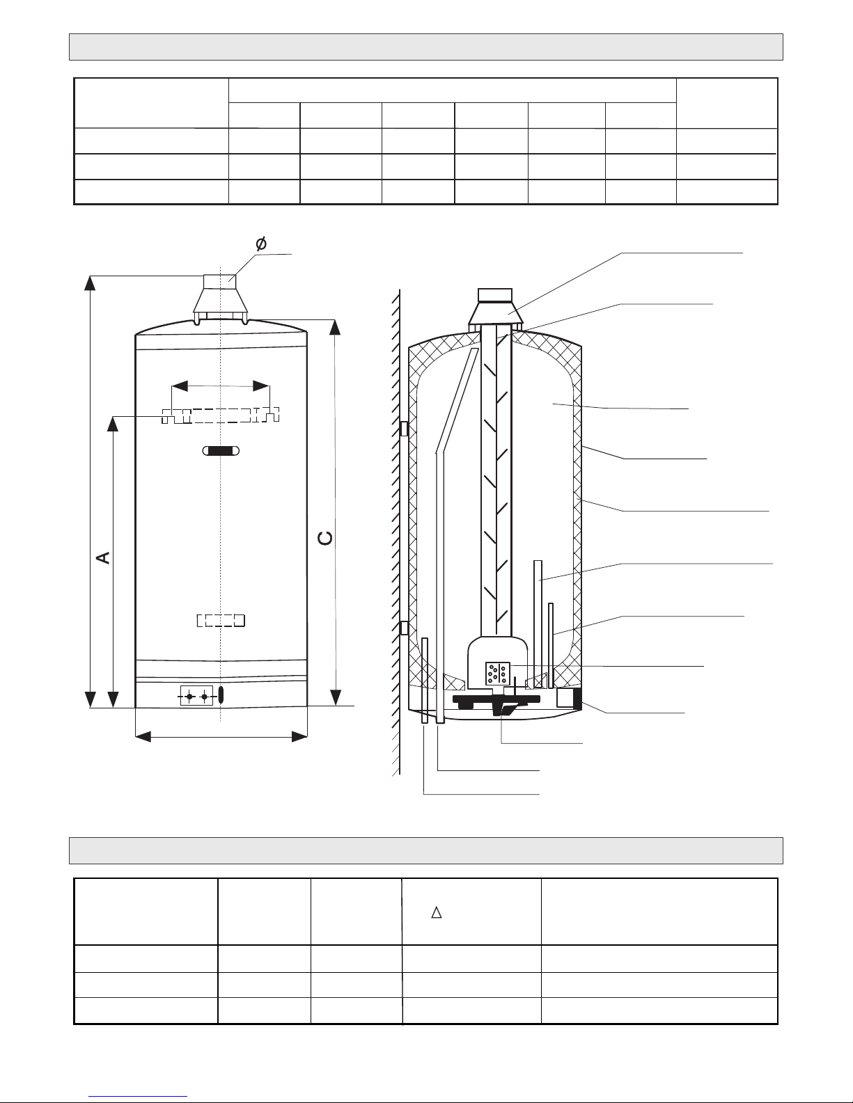
Chart No. 2: BASIC TECHNICAL DATA ON WATER STORAGE TANKS
Pict.No.1: Basic dimensions
of water storage tanks
Chart No. 1: BASIC DIMENSIONS OF WATER STORAGE TANKS
Waste gas breaker
Flue deflector
Hot water
Tank coating
Polyurethan insulation
Magnesium anodal bar
Thermostat sleeve
Main burner
Gas valve
Pilot-burner
Hot water inlet
Hot water outlet
80
5,3
55 0,56
85 0,56
TYPE
ATTACK PZ 80
ATTACK PZ 120
Volume
(L)
Power
demand
(kW)
Heating time
t = 45°C
(min)
Gas consumption
3
(m /h)
5,3
104
5,3
ATTACK PZ 150
120
150
0,56
D
B
E
F
Type
ATTACK PZO 80
ATTACK PZO 120
ATTACK PZO 150
WEIGHT
(kg)
DIMENSIONS (mm)
D
A B
C
E
F
575
880
1130
985
1240
1510
860
1155
1385
520
520
520
320
320
320
100
100
100
52
65
78
Page 5

5
* Given values refer to heating without taking water and are only informative. The real values
depend on specific conditions (temperature of inlet water, intervals of water consumption
and so on).
Inlet gas pressure: 2,0 kPa for natural gas G20
Overpressure : 1,1 kPa for natural gas
Opening pressure of safety valve: 0,6 MPa
Range of operation thermostat: about 40–72°C
ASSEMBLY
PZO water storage tank can be located in a place where for 1 kW of installed output there is 1m3
of space, according to standards. In the place where the tank is located, over the floor there
2
must an opening of 200 cm diameter. If the room is not of the minimum volume required, over
2
the floor and under the ceiling there must be vent holes, each of 600 cm area. In the rooms
3
where there are more than 2 m of space for 1 kW of installed output, no vent holes are needed.
Before hanging the storage tank on the wall i tis necessary to make sure whether the wall is
strong sufficiently to carry the weight of the tank filled with water. The wall must be from
incombustible material, otherwise it must be insulated. We recommend to balance the
storage tank.
The assembly can be performed only by a qualified company.
CONNECTING THE HOT WATER STORAGE TANK TO GAS PIPE
The assembly must be done by valid standards and precautions. On the inlet of gas to the
appliance there must be a closing element (gas valve) that should be approachable easily.
After connecting the appliance to the gas pipe the pressure test must be done and report on
first examination must be written. Gas pipe is connected directly to a gas fitting.
CONNECTING THE WATER STORAGE TANK TO WATER PIPE
- Cold water is connected to the pipe with blue marking
- Hot water outlet is connected to the pipe with red marking
On the inlet of cold water into the tank it is necessary to attach a combined safety valve with a
non-return flap that opens automatically for 0.6 Mpa pressure. After pressure decreasing the
valve closes automatically. When higher amount of water is taken and it is heated intensively,
the safety valve can open for a short time and a certain amount will flow out. To stop often
opening of the valve we recommend to take following measures:
to fit a suitable expansion tank between the storage tank and safety valve. It is not possible to
use common expansion vessels, but tanks with a rubber bag and certificate for use for water
(e.g. ZILMET expansion tanks are suitable) which are dimensioned to maximum pressure. By
using a suitable expansion tank you can totally eliminate frequent opening the safety valve.
Page 6

6
NOTE
Water must be treated by the standard. In case of deviation, an equipment for water
treatment must be installed to the tank.
WARNING
The water storage tank cannot be put into operation in any case without the safety valve fitted
and it cannot be removed.
CONNECTION TO FLUE
The appliance must be connected to a waste gas exhaust with the diameter of 100 mm. Waste
gas must be removed using the flue breaker and non-return flap against backward flow of
waste gas.
Connecting waste gas exhaust to flue must be done by the demands of standards. The flue to
which the appliance is connected must be tested by a special company. If the gas boiler and
water storage tank share operation, they can be connected to one flue only under the
condition it is dimensioned sufficiently to the output of both the appliances.
Each water storage tank works without outside source of power and it is not possible to
connect it with a flue flap electrically controlled.
Although technically it is possible to fit a bimetal flue flap due to low total savings, because of
some negative guiding signs (first of all higher noisiness of operation) it is only rarely used.
OPERATION
WARNING!
Water storage tank can be put into operation only when filled by water!
PROCEDURE OF FILLING THE TANK WITH WATER:
- Open the valve on the inlet of cold water. The valve must be always open during the
operation of the tank.
- Deaerate the tank through water-pipe fittings.
- Check the tightness of the fitting.
CHECK BEFORE IGNITION
WARNING!
* Water storage tank can be put into operation only by a trained worker of one of the service
organizations the list of which is in the supplement.
* To keep the user safe, natural gas, otherwise without smell, is mixed with aromatic materials,
so called odourisation of gas. If you smell gas in a room, do not use open faire, electric
appliances (no telephone) and do not carry out any activity which might cause sparkling. The
room must be aired, gas valve closed and the failure announced to a gas company or to a
service technician.
Page 7

7
Control button
of regulation thermostat
Piezoelectric lighter
Gas supply
to the main burner
Main gas supply
START AND PUTTING WATER STORAGE TANK TO OPERATION
Open the gas valve before the appliance.
Turn the control button of the gas fitting anticlockwise to the position of ignition burner („ “
pilot).
Press the control burner to stop and light the ignition burner by pressing the piezoelectric
lighter. It is necessary to keep the control button pressed for 10–15 seconds (pict. No.1).
Release the control button and make sure whether flame of the ignition burner keeps on
burning. If not, repeat the procedure again.
Set up the temperature required by the control button of the regulation thermostat.
Regulation of water temperature
By a regulation button, switch-off temperature can be set up in the range of 40-70°C. We
recommend to set the regulation button to 4-5 position. In this position we can reach the
temperature of 55-60°C. For this temperature only minimum of incrustation is created. For fast
heating of water in the tank it is possible to set up the button to level 7. At this level the
incrustation is higher, so it is recommended only oaboutsionally. If flame of ignition burner is
burning, thermal insulation of the heater enables keeping the temperature of heated water
for a longer period without repeated ignition of the main burner.
Water temperature can be set up by the control button of the regulation thermostat like
following:
Position 1 (about 40°C); position 2 (about 45°C); position 3 (about 50°C);
Position 4 (about 55°C); position 5 (about 60°C); position 6 (about 66°C);
Position 7 (about 72°C)
SIT 630 EUROSIT GAS VALVE
Page 8

8
WARNING!
Because of possible condensation of vapour it is not recommended to set up water
temperature to a value lower than 50°C. For running water it is necessary to mix water in the
fitting.
PUTTING THE WATER TANK OUT OF OPERATION
The procedure is following:
Turn the control button into the position OFF
Stop gas supply to the appliance
For putting the appliance back to operation it is necessary to follow previous chapters
WARNING!
Control elements of the gas fitting can not be manipulated violently. Damage can cause gas
release and even explosion. If turning the control element causes problems, service should
be called immediately.
SAFETY DEVICE
The procedure of burning is protected by flame fuse that closes gas supply automatically
when ignition flame goes off. Opening time of the fuse is about 8 seconds but it can not
overcome 15 seconds. Closing time is about 45 seconds but it can not overcome 60 seconds.
TEST OF THE DEVICE
When putting the device to operation the organization is obliged to check:
safety times of flame fuse
adjustment of the appliance to a certain thermal output
the procedure of burning the main burner from ignition flame (must be continuous)
whether the operation thermostat is working
whether the safety valve is working
whether the device is gas resistant and water resistant
whether the draught breaker is working and waste gas is exhausted properly
documentation of the device
POSSIBLE FAILURES – CONDENSATION OF VAPOUR
Vapour present in waste gas can condensate and then drop on hot surfaces. In this case some
hiss and crackle can be heard. After heating water this sound will stop.
CONDENSATION OF VAPOUR CAN HAPPEN IN FOLLOWING CASES:
New storage tank is filled with cold water for the first time.
Gas burning starts but water is still cold.
If in a short time a big volume of water was released and water coming into the boiler is too
cold. If this occurs too often, it is necessary to set up the regulator of temperature to a higher
value.
Page 9

9
FUME, SMELL OF FUME
Smell of fume after ignition of the storage tank is not a defect or anything unusual. It is just a
result of possible burning out of oil deposit on metal parts of the tank and the smell will stop in
a short time.
UNFAMILIAR NOISE
This can be sensed in case of expansion of metal parts when heating and cooling down
periodically.
EMERGENCY THERMOSTAT
The storage tank is equipped with an emergency thermostat which in case of failure of
regulation thermostat followed by higher temperature in the tank closes gas supply to main
and ignition burners. If both the burners go off, it is necessary to wait until water in the tank
cools down under 40°C and then relight the ignition flame again. If it is not possible to put the
storage tank to operation again, service must be called immediately.
PERIODICAL MAINTENANCE
Periodical maintenance is important to make the storage tank reliable. User is
recommended to sign a contract with a service company on regular checks and
maintenance of the storage tank which can prolong life and ensures operation without
failures.
To make repairs and maintenance possible and easy, there must be free approach to the
storage tank. Air supply must not be limited.
The storage tank should be cleaned of dust and can not be covered by towels, rags and other
flammable materials. Outside coat can be cleaned with a rag soaked with soapy water and
dried with a towel.
If in the room, where the storage tank is located, some works concerning to change of
surroundings are done, all the storage tank including ignition flame must be put out of
operation.
When the storage tank is off and the outside temperature drops under 0°C, water must be
released from the tank.
WARNING!
If the storage tank is put out of operation for a longer time (2 weeks and more) including
ignition burner, hydrogen, that is highly incombustible, can be released from hot water
distribution. When putting the tank back to operation, we recommend to open hot water
taps for several minutes.
If hydrogen release occurs, during water running some strange noise can be heard. When
the noise stops, the burner can be ignited and there will be no danger of spontaneous
ignition.
Page 10

10
WARNING FOR USER!
When taking the storage tank over make sure whether the letter of guarantee is confirmed
properly.
Reclaim defects immediately otherwise you lose your right for guarantee. Check whether
the equipment was not damaged during transport and if it was, claim the guarantee at the
transporter.
Reclamation of the completeness of the delivery is carried out in compliance with
Commercial Code and Civil Code at the deliverer.
Assembly of the product can be done only by a qualified worker or organization with a valid
certificate. Repairs of the storage tanks can be performed only by service organizations
included in the list. Unqualified intervention into the storage tank can cause losing the right
for a guarantee repair free of charge!
INSTALLATION AND ADJUSTMENT OF GAS VALVE
Only for qualified workers!
Adjustment of the outlet pressure
All the adjustments must be done according to technical
parameters of the appliance. Inlet and outlet pressure are
checked by A and B outlets.
Maximum pressure: Set up the control button to maximum
level of 7, by C screw set up pressure of 10 mbar.
Setting up gas flow to ignition burner
By gradual screwing D screw the flow decreases, by
releasing it increases.
If you want to put gas flow adjustment to ignition burner out
of operation, screw the D screw up to stop.
WARNING:
After finishing all the activities it is necessary to check
tightness of gas fitting and verify whether the appliance is
working.
BOILER ACCESSORIES, DOCUMENTATION
A part of the gas storage tank is a safety valve (0,6 mbar)
and draught breaker
Instruction for use
Because of permanent development of products we reserve the right to change
technical data.
A
measuring
outlet gas
pressure
B
measuring
inlet gas
pressure
+
-
+
-
C
setting up
the outlet
of main burner
D
setting up
the output
of pilot-burner
Page 11

11
Stamp, signature of the service organization: ....................................
Obligatory service inspection after the 1st year of operation
Date: .............................
Obligatory service inspection after the 2nd year of operation
Stamp, signature of the service organization: .................................Date: ..........................
Data of the customer: (legibly)
Name and surname:
...........................................................................
Street: ................................................................
ZIP code, town: ..................................................
Tel.: ....................................................................
Device commissioning report
Serial number: ...............................................
Date of commission: ......................................
Service organization:
.......................................................................
Stamp, signature
This page serves for confirming the service inspections and is kept by the customer!
NOTES
Page 12

ATTACK, s.r.o. – 05/2014
ATTACK, s.r.o.
Dielenská Kružná 5020
038 61 Vrútky
Slovenská republika
Tel: +421 43 4003 101
Fax: +421 43 3241 129
E-mail: kotle@attack.sk
Web: www.attack.sk
Výrobca ATTACK, s.r.o. si vyhradzuje právo technických zmien výrobkov bez predchádzajúceho upozornenia. • ATTACK, s.r.o. producer reserves the right to change technical parameters and dimensions of
boilers without previous warning. •Der Hersteller ATTACK, s.r.o. behält sich das Recht der technischen
Veräderungen an Produkten ohne eine vorige Warnung. •Изготовитель ATTACK, s.r.o. оставляет за
собой право изменения технических параметров и размеров котла без предыдующего предупреждения. •Le producteur ATTACK, s.r.o. réserve le droit des modifications techniques sans l‘avertissement
précédent. •Productor ATTACK, s.r.o. reserva el derecho de cambios técnicos sin advertencia anterior.
 Loading...