

Page 1

W W W . A T T A C K . S K
BIOMASS BOILER
ATTACK PELLET 30
AUTOMATIC PLUS
INSTRUCTIONS FOR USE
Page 2

Page 3
3
ATTACK PELLET 30 AUTOMATIC Plus – Boiler for pellet combustion
Important information:
Boiler for wood pellet combustion.
Installation, test heat-up and training of attendance must be performed by trained service
technician, who has to fill-in the protocol about boiler installation.
Recommended boiler operation temperature is 80–90°C. Lower operation temperature may cause
creation of condensate, shorter life-time of boiler and warranty expiration.
The only fuel to use are pellets, adequate to the approved fuel specification.
Appropriate boiler output represents very important condition of economic operation and correct
boiler function. Nominal boiler output has to be adequate to thermal losses of the heated object.
It is the responsibility of the installer to ensure compliance to all relevant building regulations.
Please, read this manual before starting-up the boiler.
Keep this manual for attendance on a suitable place in the boiler room. It is recommended to
keep it in a plastic pack and t o hang i t on a visi ble place on t he wall to be reached b y technici an,
when doing service in your boiler room.
Boiler door and connections between boiler and chimney have to be airtight.
Overpressure in combustion chamber should be at least 5 pascal (0,5 mm of water column, resp.
0,05 hPa).
The PEL30AP appliance is intended for combustion of wood pellets and it cannot be used for
combustion of other fuel types.
The PEL30AP appliance for pellet combustion can be installed in a boiler room only, in
conformity with prescriptions of the local fire safety / construction authority.
WARRANTY FOR BOILER IS NOT VALID IF:
it is not operated with prescribed fuel - pellets adequate to the approved fuel specification.
there is no mixing device Regumat ATTACK-OVENTROP installed in the system to
ensure temperature of the boiler return water over 65°C.
WARNING SIGN
Warning sign is used in this manual to prevent potential hazards by breaking the instructions. Two
types of warnings are used in this manual:
WARNING – warns about dangerous situations and situations that may cause health injury
or damage by breaking the indespansable measures.
ATTENTION – warns about less dangerous procedures that may cause safety hazard or
damage of property.
Page 4

4
Contents
Important information: ......................................................................................................................... 3
Contents ............................................................................................................................................... 4
Introduction: ......................................................................................................................................... 5
General description .............................................................................................................................. 5
Purpose of usage .................................................................................................................................. 6
Boiler description ................................................................................................................................. 6
Boiler regulation .................................................................................................................................. 7
Technical parameters ........................................................................................................................... 7
Dimensions of boiler ATTACK PELLET 30 AUTOMATIC Plus ..................................................... 8
Main parts of boiler ATTACK PELLET 30 AUTOMATIC Plus ....................................................... 8
Assembly and installation of boiler ..................................................................................................... 9
Boiler connection scheme .................................................................................................................. 11
Burner connection scheme ................................................................................................................. 12
Flue connection .................................................................................................................................. 13
Boiler protection against corrosion .................................................................................................... 14
Binding norms for boiler projecting and assembly: ........................................................................... 14
Operation prescriptions ...................................................................................................................... 15
Maintenance of heating system with boiler ....................................................................................... 17
Recommended schemes of connection .............................................................................................. 18
Technical description of burner ......................................................................................................... 19
Technical data of burner .................................................................................................................... 20
Voltage and energy consumption of burner ....................................................................................... 20
Description of burner function ........................................................................................................... 21
Usage of pellet burner ........................................................................................................................ 22
Menu buttons nad their function ........................................................................................................ 22
Messages on display........................................................................................................................... 23
Menu messages .................................................................................................................................. 24
Production settings ............................................................................................................................. 25
How to install pellet feeder and container ......................................................................................... 27
Burner start ......................................................................................................................................... 27
Burner shut down ............................................................................................................................... 27
Emergency shut down ........................................................................................................................ 28
Cleaning and maintenance ................................................................................................................. 28
Troubleshooting ................................................................................................................................. 29
Possible causes of faults ..................................................................................................................... 29
Decomposed view .............................................................................................................................. 31
Accessories......................................................................................................................................... 32
Advanced menu.................................................................................................................................. 32
Instructions to disposal of product after expiration of its lifetime ..................................................... 36
Disposal of packaging ........................................................................................................................ 36
Accessories......................................................................................................................................... 36
Notes .................................................................................................................................................. 37
Page 5

5
Introduction:
Dear customer,
thank you for your confidence, expressed by purchase of our product – the ATTACK PELLET 30
AUTOMATIC Plus boiler for pellet combustion.We wish it serves you well and for a long time.
Proper attendance of the boiler is one of the conditions for reliable and correct operation.
Therefore it is necessary to read this manual carefully. This manual is written with respect to the
correct boiler function.
Main conditions of the correct boiler operation are:
selection of the correct boiler type and output
impeccable commission
correct attendance
periodical technical maintenance
reliable service
General description
The ATTACK PELLET 30 AUTOMATIC Plus boiler for pellet combustion is intended for
economical and ecological heating of dwelling houses, cottages, small plants and similar objects.
Wood pellets are prescribed fuel for this boiler.
Marking of the boiler:
ATTACK PELLET 30 AUTOMATIC Plus
PELLET – Boiler for wood pellets combustion
30 – Output of boiler
AUTOMATIC – Automatic cleaning of ashtray
Plus – Automatic cleaning of exchanger by movable turbulators
Page 6

6
Purpose of usage
The ATTACK PELLET is a modern boiler for wood pellet combustion. By its technology it saves
environment and offers comfort comparable with usage of gas boiler.
Boiler is intended for heating of family houses, shops, industrial objects and other similar buildings.
Boiler description
The ATTACK PELLET 30 AUTOMATIC Plus boiler burns pellets with diameter o f 6–10 mm and
max. length of 35 mm.
Construction of boiler is consists from combustion chamber with partition, heat exchanger and flue
connection.
Boiler body cooled by water is a basic part of boiler. It is welded from boiler steel plates of 3–6 mm
thickness to ensure long lifetime. Tubular exchanger is equipped with turbulators, ensuring better
heat transpher into heating water. They also serve for exchanger cleaning to provide uniform
efficiency.
Combustion takes place in the burner. Optimal conditions for burning and output regulation are
ensured electronically, by controlling fuel and air supply, in dependence on the he ating parameters
required by user.
Construction of burner, combustion chamber and exchanger ensures optimal burning of all
combustible contents.
Boiler is equipped with device for automatic ash removal from the bottom of combustion chamber
into the external box. Ash removing is set by production for every 12 hours.
Boiler body is insulated with mineral wool. Boiler covering is treated by powder technology.
Boiler can be accessorized with device for fuel suppl y and with pellet hopper of 450 l. In case of
fuel shortage or burner failure it is possible to use electrical coil up to the 6 kW output (and 450 mm
length), installed into the flange with G 6/4” internal thread on the left side of boiler. This coil can
be also used as an anti freeze protection. Coil is equipped with operating and emergenc y thermostat .
Its electrical installation is independent from electrical installation of boiler.
Page 7
7
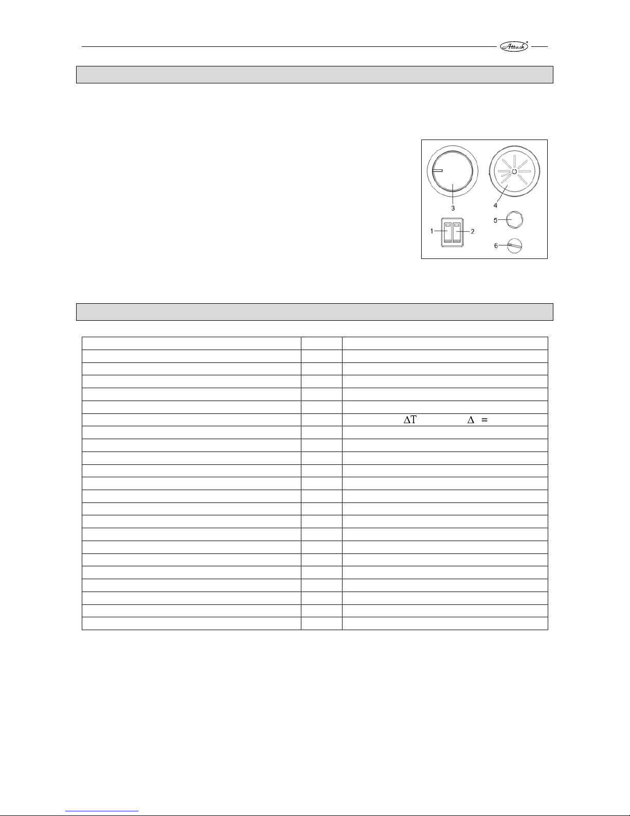
Boiler regulation
The ATTACK PELLET 30 AUTOMATIC Plus boiler for pellet combustion is regulated by control
panel placed on the upper covering.
1 – Main boiler switch – Plugs boiler into / off the power
2 – Burner mode switch – switches burner between stand-by and
operating mode
3 – Boiler thermostat – setting of boiler operating temperature
4 – Thermomanometer
5 – Reset button of the emergency thermostat – under cover
6 – Fuse 10 A / 250 V
Operation, parameters and settings of burner are described in the
appendix of this manual.
Technical parameters
Boiler type PELLET 30 AUTOMATIC Plus
Boiler output kW 30
Output range kW 8–30
Heat exchange area m
2
1,9
Prescribed chimney draught Pa 15–20
Max. operating water overpressure kPa 250
Pressure loss of water Pa 152 (ΔT=10K); 38 (ΔT=20K)
Boiler weight kg 355
Flue diameter mm 150
Boiler height mm 1220
Boiler width mm 575
Boiler depth mm 1 250
Protection of el. parts IP IP 40
Max.el.input (by ignition) W 600
Operating el. input W 90
Boiler efficiency % 90,6
Boiler class by CO emission (under EN 303-5) 5
Flue temperature by nominal output °C 143
Prescribed fuel Wood pellets d=6–10 mm, l=35 mm max.
Average consumption kgh
-1
2,4–6,9
Volume of water in boiler l 62
Range for setting of heat. water temperature °C 60–90
Connection voltage V/Hz 230/50
Prescribed temperature of boiler return water within operation is 65°C.
Recommended operating temperature of water in boiler is 80–90°C.
The ATTACK, s.r.o. manufacturer reserves right for change of technical parameters and boiler dimensions without
previous announcement.
Page 8

8
Dimensions of boiler ATTACK PELLET 30 AUTOMATIC Plus
Main parts of boiler ATTACK PELLET 30 AUTOMATIC Plus
1 – boiler body 7 – turbulators
2 – covering 8 – flue collector with flue exhaust
3 – detachable ash container 9 – flow connection 1“
4 – door of control opening 10 – return connection 1“
5 – burner 11 – inlet / outlet valve
6 – tubular exchanger 12 – ash tray
Page 9

9
Assembly and installation of boiler
Installation of boiler
Only the person with valid approval for installation and assembly of the heat technolog y devices
can install the boiler. Fo r installation it is necessary to elaborate a project in conformit y with the
valid prescriptions. Technician must check, if information on data plate comply with project and
accompanying documentation, before doing the installation. Boiler must be connected in
conformity with valid prescriptions, norms, regulations and this manual. Manufacturer takes no
responsibility for damages caused by incorrect connection, eventually by incorrect operation.
Placing of boiler
Boiler is intended for installation and operation in premises with elementary environment
(AA5/AB5) under the STN 33 2000-3. By boiler installation it is necessar y to keep safety distance
of its surface from flammable materials in dependence on the grade of flammability:
from materials of flammability B, C1, C2 200 mm
from materials of flammability C3 400 mm
from materials, which grade of flammability
has not been approved under the STN 73 0853 400 mm
Examples of division of constructive materials by the grade of flammability:
grade of flammability A – inflammable (brick, block, ceramic tiles, mortar, plaster)
grade of flammability B – very difficult to ignite (heraclith, lignos, boards from bazart felt)
grade of flammability C1 – hard flammable (beech, oak, plywood, wersalit, hardened paper)
grade of flammability C2 – medium flammable (pine, spruce chipboard, solodur)
grade of flammability C3 – lightly flammable (boards from wood fibres, polyurethane, PVC,
foam rubber, polystyrene)
If boiler stands on the floor from flammable materials, it must be protected by inflammable heat
insulating pad, excessing boiler edge for 150 mm at least.
It is possible to use materials of the flammable grade A as inflammable and heat insulating
materials.
Any items from flammable materials cannot be placed on the boiler and in distance shorter than
500 mm.
When placing boiler in the boiler room, there should be free space le ft of at least 1 m beyond and
0,5 m from the sides and rear part of boiler. Above the boiler, there should be free space of at least
1 m. This space is necessary for ordinary operation, maintenance and eventual boiler servicing.
It is inadmissible to place the ATTACK PELLET 30 AUTOMATIC Plus boiler in dwelling
premises (including corridors)!
Air inlet
For correct boiler operation, it is necessary to ensure sufficient air supply for combustion. Minimum
area of the air inlet is 200 cm2.
Boiler connection into heating system
Installation and service of the ATTACK PELLET 30 AUTOMATIC Plus boiler can be performed
by trained service technician only. Before boiler installation into the older heating system, it is
necessary to flush the whole system to clean it. Heating system must be filled with water fulfilling
requirements of the STN 07 7401:1991 and its callosity cannot exceed 1 mmol/l and concentration
Ca2+ 0,3 mmol/l. By unkeeping these conditions, warranty for boiler expires!
Page 10

10
Selection and way of connection of regulation and control elements
Boiler is delivered with basic regulation and control equipment. Connection of these elements is
given on connection scheme. It is recommended to extended boiler regulation for next regulation
elements for more comfortable and economical operation. Every pump in the system must be
controlled by individual thermostat to prevent boiler undercooling at the return water inlet (return
connection) under 65°C.
Connection of these elements is proposed by projectant, following specifical conditions of heating
system. Electrical installation in combination with sufficient boiler equipment must be done by
specialist under the valid norms.
Connection to electricity mains
Boiler is connected to el. mains 230 V / 50 Hz by plug with fork. Plug of M type has to be replaced
by service technician with the same type of plug. Appliance must be pl aced in the way enabling
attendance to reach the connection fork (under the STN EN 60335-1+A11:1997). Connection of el.
socket must be in conformity with the STN 33 2000-4-46 norm. Socket must be equipped with
middle protection stick, connected to the PE conductor. It is not permitted to use different cable
distributors and extensions. Due to safety, power inlet must be freely accessible, when being
connected to the el. mains.
Page 11

11
Boiler connection scheme
N
N
N
L
11 10
9
8
7
6
5
4
3
21
TP
33
4
1
33
4
TP
4
33
33
4
33
3
1
33
F
C
TK
HT
1
3
2
4
5
6
C
1
C
1
V
HV
42
33
TOC
1
3
COLOUR MARKING:
– Brown
– Yellow-green – Black – Blue – Grey – Orange
DESCRIPTION:
5 6
TV
K6/3
PE
N
1
2
3
4
5
6
A
B
33
1
2
3
4
5
6
N
PE
K6
/
5
1
2
3
4
5
6
N
PE
N
CONNECTION
CABLE
3
4
2
2
0
V
,
5
0
h
z
33
4
33
4
4
2
4
2
4
1
2
3
4
5
6
N
N
N
1
2
3
4
5
6
N
N
N
PE
K6/2
K6
/
1
4
4
NOTES:
1. When connecting TP and TV it is necessary
to remove clip between pos. 3 and 4 on
terminal
2. When connecting TOC i tis necessar y to
remove clip between pos. 6 and 8 on
terminal
LLL
LLL
L
L
L
L
L
L
L
L
3
3
3
3
3
3
3
L
L
1
1
L
L
L
L
L
L
HV – main switch
V – burner switch
TK – boiler thermostat
TP – room thermostat
HT – emergency thermostat
C – capacitor
F – fuse 10A/250V
TV – three way valve
TOC – thermostat of circuit pump
A – motor of ash removing
B – motor of turbulator move
PE – grounding terminal – flat double stick
K6/1 – 6-pole connector – power supply of motors
K6/2 – 6-pole connector – connection with K6/1
K6/3 – 6-pole connector – connection with K6/4
K6/4 – 6-pole connector – connection with K6/5
K6/5 – 6-pole connector – power supply of burner
Page 12

12
Burner connection scheme
1
L
L
L
LL
L
NNNN
**
3
2
34
567
89
12
13
PE 15 16
033
NL
+
-
EKM0EK
025EK025EK
EK
027
1
2
4
5
11
16
15
17
13
14
12
8
6
10
9
*
F1
F2
F3
F5
L
1 – Basic electronics
2 – Display electronics
3 – Electronics of cleaning
4 – Display
5 – Data cable
6 – Feeder
7 – Motor of ash removing
8 – Socket for feeder
9 – Ventilator
10 – Sensor of ventilator rotations
11 – Gear of cleaning
12 – Boiler temperature sensor
13 – Photocell
14 – Coil
15 – End–switch
16 – Thermal fuse
17 – Connector
F1
F800mAL250V – – Ventilator
F1AL250V
F2
– – Pellet feeder
T6 3AL250V
F3
– –Ignition
F800mAL250V
F5
– – Gear of ash removi ng
– Contact without potential
L1
L2
L3
PE
N
N
12
3
456
1
2
3
4
1
2
3
4
1
2
3
4
1
2
3
4
COLOUR MARKING:
– Black
– Blue
– Yellow–green
CONNECTION
CABLE
Page 13

13
Flue connection
Flue connection must empty into chimney vent. If it is not possible to connect boiler to chimney
vent directly, appropriate extension of flue should be as short as possible (not longer than 1 m),
without additional heating area and it has to ascend in direction towards chimney. Extensions of
flue connection must be mechanic ally firml y joined, tight a gainst flue leak age and easil y cleanable.
Extensions of flue connection cannot lead through foreign dwelling or utility units. It is necessary to
eliminate usage of elbows and horizontal parts.
Chimney
Connection of appliance to chimney vent must always be done with agreement of the appropriate
chimney authority. Chimney vent must create sufficient draught and reliably exhaust flue into
atmosphere under all practically possible conditions. Correct dize of the chimney vent ensures
correct boiler function. Chimney draught directly depends on its diameter, height and roughness of
its internal wall. Chimney vent must be sufficiently insulated to prevent creation of condensate.
Temperature of the area of 1 m under the chimney collar cannot be lower than 60°C. Any other
appliance cannot be connected to the chimney joined with the boiler. Diameter of chimney cannot
be smaller than boiler outlet. Chimney draught must achieve prescribed values. However, it cannot
be too high, not to decrease boiler efficiency and not affect the combustion (not to disturb the
flame). In case of too strong draught i tis necessary to install throttling flap between boiler and
chimney.
Information values of chimney diameter
20 x 20 cm min. height 7 m
20 cm min. height 8 m
15 x 15 cm min. height 11 m
16 cm min. height 12 m
Exact chimney dimension is determined by the STN 73 42 10. Prescribed chimney draught is given
in the Technical parameters.
Page 14

14
Boiler protection against corrosion
Suitable solution of this problem is usage of the mixing device Regumat Attack-Oventrop). This
solution enables creation of separate boiler and heating circuit and prevention against boiler
undercooling under 65°C. Thereby it comes to decrease of water steams condensation and acid and
tar creation in boiler exchanger and combustion chamber.
Usage of device is a condition of the valid warranty.
Regumat serves to keep temperature of the return heating
water flowing into the boiler over 65°C, when thermostatic
head is set to the 5–6th grade. Temperature of 60°C in the
return connection causes increased creation of condensate
and tar and consequently, shorter lifetime of boiler.
Technical parameters:
Clearance DN25
Max.pressure 10 bar
Max.temperature 120°C
Value kvs 3,9
The Regumat consists of three way mixing valve, circuit pump, closing valve, thermometers and
isolation. This solution is advantageous due to its compactness, easy attendance and guaranted
protection of the boilers heat exchanger.
Regumat for boiler ATTACK PELLET: ordering code - DPP25003
Binding norms for boiler projecting and assembly:
STN EN 303-5 – Heating boilers for solid fuels
STN 734210 – Design of chimneys and flue exhausts
STN 920300 – Fire safety of local appliances and heat sources
STN EN 60335-1+A11 – safety of el. appliances for household
STN 061000 – Local appliances for solid, liquid and gaseous fuels
STN 060310 – Central heating projecting and assembly
STN 060830 – Safety device for central heating and DHW
STN 077401 – Water and steam for heat energy devices with operation pressure of steam up to
8 MPa
STN 33 2000 4-46 – Electrical installations of buildings. Part 4: Ensuring safety.
STN 33 2000-3 – Electrical installations of buildings. Part 3: Determination of basic characteristics
STN 061008 – Safety of heat devices
STN EN ISO 11202 – Acustics
STN EN ISO 3746 – Acustics
STN EN 62233 – Measuring methods of electromagnetic arra ys o f appliances for household and
similar devices by the exposition of persons
STN ISO 80000 – Measurements and units
Page 15

15
Operation prescriptions
Boiler preparation for operation
Before starting the boiler, make sure, that the system is filled with water, deareated and there is no
pressure decrease of the heating water. Check tightness and construction of flue exhaust. To ensure
quality function, the boiler must be attended in conformity with instructions given in this manual.
Only adult person can operate the boiler.
Boiler start-up
Boiler is switched to the stand-by mode by the main switch (left button of double-switch), placed on
the boiler control panel. This is signalized by red control light in the main switch. Boiler is started
by switching the burner mode switch on (right button of double switch). This is signalized by
control light in the switch. Knob of boiler thermostat has to be set to the required temperature of
heating water. By clockwise turni ng the thermostat is the required temperature increased and vice
versa. Fuel in the burner is ignited automatically by el. coil built inside. Boiler operation is
automatic and it is controlled by boiler thermostat and other regulation elements, that can be
connected into boiler terminal (e.g. room thermostat, programmable regulator, ...). Details about
setting the burner parameters are described in the next chapters of this manual.
ATTENTION!
Condensation and condensate leakage may occur b y first heat-up. After lo nger heating, condesation
is eliminated.
If the boiler was out of order for longer period (turned off or faulty), it is necessary to be more
careful when starting it again. After longer idle period it may come to pump blockage or water
leakage from system.
Regular and proper cleaning is important to ensure sustainable output and boiler life-time. Poor
cleaning may cause boiler damage. All boiler door have to be tightly closed during the operation.
Fuel
By burners for wood pellets combustion:
APPROVED FUEL SPECIFICATION
Moulded wood pellets
Measured weight: 600–750 kg/m3
Heat value: 4,7– 5,0 kWh/kg
Size/diameter: 6–10 mm
Size/length: Attention! max. 35 mm
Moisture max.: 12 %
Ash content: 0,5–1 %
Dust content: max. 3 %
Ash smoulder temperature: min. 1 100°C
Fuel must be in conformity with requirements of the norm DIN 51 731.
Methods of boiler regulation
Boiler regulation without room thermostat
For this case there is interconnection installed on contacts of boiler electrical terminal (TP-U1/ U2).
Boiler is regulated according to the boiler temperature set on the boiler thermostat placed on the
boiler control panel.
Page 16

16
Boiler regulation with room thermostat
Boiler is controlled by the room t hermostat, conn ected to t he terminal con tacts (TP - L1/L2) instead
of interconnection, that has to be removed. The required boiler temperature will be considered a s
well. Also other type of requirement can be installed instead of the room thermostat – e.g.
programmable regulator of heating.
ATTENTION!
There is dangerous contact voltage of 230 V on the connection contacts of the room
thermostat! Boiler must be disconnected from electricity by any action into the electrical
terminal or boiler electrical installation!
Boiler protection
Boiler is equipped with emergency thermostat. If the boiler temperature exceeds 110°C, boiler
safely gets out of order. When the boiler temperature decreases, it is possible to start the boiler
again by using the reset button placed on the front control panel.
Fuel refill
Fuel is refilled in the container that belongs to the optional boiler accessories. Fuel should be
refilled before the pellets in the container are totally consumed.
ATTENTION! Fuel container can be open only when fuel is being refilled, eventually by
cleaning. Container has to be closed during the boiler operation.
Ash removing
The ATTACK PELLET 30 AUTOMATIC Plus boiler is equipped with device for automatic ash
removing into the detachable box. It is necessary to check the box 2x per season and to empty it, if
necessary. Stop the boiler for a short time, when removing the ash container.
When emptying the box (see the picture):
1. Close inlet openin g into the container b y pulling the lever on the container rear side full y to
the left
2. Release lever catches on container sides
3. Detach container from inlet tube of door cover by pulling it to yourself
4. Remove the ash
Do the reverse procedure to fit the container back.
When cleaning bottom of the combusti on chamber, stop the boiler for a short time. Empty the iron
ashtray, eventually – sweep the boiler bottom. Ash tray is placed in the bottom part of boiler, behind
the ash tray door. Use gloves by manipulation with ash tra y to prevent burning your hands. When
the ash is removed, it is necessary to put the ash tray back and to close the ash tray door tightly.
WARNING – Do not operate the boiler without the ash container fixed with the closed upper
cover (possible flue leakage) – life safety hazard!
Page 17

17
1
2
3
Short-time boiler stop
If you wish to stop the boiler for a short time, turn the burner switch off and let the fuel burn down
in the burner. Do not turn off the main switch.
Long-time boiler stop
When stopping the boiler for a long time, firstly – turn the burner switch off and let the fuel in the
burner burn down. After the boiler is cooled down to 30°C, turn the main switch off and disconnect
the plug from power socket.
Maintenance of heating system with boiler
At least 1x in 14 days it is necessary to check, eventually to refill water in the heating system.If the
boiler is out of order during the winter, there is danger of water freezing in the system. Thereby it is
reasonable to drain the water out. In other cases, drain the water out only, when it is absolutelly
necessary and for as short period as possible. After the heating season it is necessary to cl ean the
boiler properly (after long idle period, the ash has to be sweeped out from t he container / ash tray,
walls and bottom of combustion chamber have to be cleaned as well) and replace the damaged
parts.
Exchange of the door sealing cord
Remove the old sealing cord by screw driver and clean the groove, where the cord is placed. Take
new cord and put its leading end between the horizontal parts of the groove. Use hand, eventuall y
hammer to fit the cord into the groove along the door edge.
Fitting the hinges
After a particular period, it may come to abrasion of the sealing cord. To endure tightness of door, it
is necessary to change their position b y screwing the hinges. Inspection door is fixed to the boiler
body by a lon g pin. Pull the pim out and screw the hinge by turning to change its position. Fit the
door and put the pin back into the hinge.
WARNING! To pull the pin of the upper door out, it is necessary to demount the upper boiler
covering. To protect the health, the boiler has to be turned off and the plug has to be disconnected
from electrical socket.
Page 18

18
Recommended schemes of connection
12
43
Page 19

19
Technical description of burner
Burner operation is based on principle of pellets falling from pellet feeder through inlet hose and
inlet pipe on the grate to be burned.
Burner is equipped with electric ignition device, that automatically lights pellets fallen on the grate.
Ignition begins, when thermostat gives instruction to burner. Burner has own built-in thermostat (if
there is no boiler / external thermostat, eventually combined device with room thermostat). Its
temperature sensor must be in suitable casing in the boiler´s water coat. Switch-on and switch-off
temperature can be adjusted via the burner menu buttons. Actual operation data are visible on
display.
ATTENTION! Head of boiler temperature sensor must not be treated with any contact
liquid, nor paste.
Burner output is set from production for the range of 14–30 kW and it is divided into 3 levels:
1. (14 kW), 2. (22 kW) and 3. (30 kW).
Selected output level is written on display during the operation. Output level can be selected by
burner menu buttons and displayed information. Output range can be changed in advanced menu in
two levels: 8–12 kW and 14–30 kW.
Burner is equipped with automatic grate cleaning mechanism. When thermostat achieves required
temperature, the burn-down c ycle is started, the grate goes out to be cleaned by scraping. Ther eby,
the longer usage period is ensured, with no need to dismantle burn er from boiler bod y. Burner uses
control system to regulate gear of ash removing auger and gear of exchanger cleaning by
turbulators.
Boiler convection parts should be cleaned periodically to keep high efficiency of heating.
Burner is intended for combustion of wood pellets with diameter of 6–10 mm.
Burner is manufactured following the industrial norms and prescriptions and it was tested and
approved in conformity with directives about low voltage devices and with directives about
electromagnetic disturbance.
Page 20

20
Technical data of burner
Model PELH30Plus
Fuel Wood pellets, 6–10 mm
Mode 8–12 kW; 14–30 kW
Output range 8–30 kW, by 2 kW
For boilers with heating chambers up to 3 m²
Weight 28,5 kg
Main voltage Main current Hz
~230 V 10 A fuse 50
WARNING! Electrical installation must be done by certified electrotechn ician. Main cables
can be exchanged by approved electrotechnician only.
Voltage and energy consumption of burner
Component Mains/Volt Min./Max. voltage Fuse
Display 5 V DC 1 W --------Ventilator 230 V~ 15–58 W 800 mA
Circuit board 230 V~ --------Grate cleaning 24 V DC 10–50 W switched
Ignition 230 V~ 600 W 6.3 A
External pellet
feeder
230 V~ 15–220 W 1 A
Ash removing 230 V~ 15–220 W 1 A
Page 21

21
Description of burner function
ATTENTION! Burner works with boiler thermostat only, eventually extended with room
thermostat. In both cases it has to be connected through protection against boiler overheating.
Normal start-up
When thermostat gives instruction to burner, ventilator is started and photocell controls flame. If
there is no flame, then comes the instruction for test blow-through of burner. Afterwards, pellets
start falling into burner within the period stated by control system and ignition is activated. When
the phase of fuel supply for ignition ends, control system awaits flame signal from photocell.
When photocell recognizes flame, small amounts of pellets are falling within the transition
period.Duration of this period depends on the output level set on burner. Pellet supply is being
continually increased, unless it is adequate to the required output.
This amount is further supplied into burner, until the operation thermostat gives instruction to stop.
This signal stops pellet supply, while ventilator continues with air supply into burner.
When photocell recognizes fuel burn-down, the burner blow-through begins.
According to the adjusted delay, after fuel burn-down, burner cleaning begins – burner grate move s
out against scraper and ash with unburnt pieces fall through front side of burner bottom into ash
tray.
After the grate moves back, the burner awaits new signal from thermostat.
ATTENTION! Grate drive unit is very strong and it may cause danger. Never put any body
parts or other foreign objects into burner, when it is operating.
Normal start, when there is still flame in burner
If photocell recognizes flame during the start-up phase (e.g. after short-time power failure), control
system immediately begins transition period. Pellet burner continues in operation as by normal start.
(see above)
Normal start, when no flame is recongnized by control system
Normal start-up process runs even in case, if there is no flame signal received b y control system.
Shortly after, system begins the new start-up trial again, when fuel suppl y for ignition is reduced to
45 % and it can be reduced during the whole ignition period. These parameters can be changed in
service menu – by trained person only. If the second trial fails, all functions are turned off and alarm
is activated. This alarm is indicated on display.
ATTENTION! Make sure, that sufficient flue gas temperature had been achieved. It has to
be at least 60°C – one meter under the chimney top. Lower temperature should be consulted with
chimneyer. Flue gas temperature lower than 60°C during the combustion process increases risk of
chimney damage by condensation.
Page 22

22
Usage of pellet burner
Pellet burner needs air for combustion. Thereby, boiler room must have opening for air inlet of at
least 200 cm2.
Pellet burner must not be started before it is verified, that smoke can freely flow through boiler and
chimney into atmosphere.
Pellet are supplied into b urner from external feeder, connected to pellet co ntainer. Feed er has to be
installed under the 45°angle to ensure the best fu nction and uniform fuel supply. Feeder should be
able to supply approximately 10 kg of pellets per hour of continual operation / requirement for
pellet supply.
Pellets must be stored in well ventilated room without moisture, or in specially designed container.
ATTENTION! Burner consists from components of high quality, that must not be replaced
with less quality spare parts. If components are replaced by other than original spare parts, warrant y
expires.
Menu buttons nad their function
Burner functions are set by menu buttons under display. ( see also options of settings under the
Production settings – below).
How to change settings of pellet burner:
„S“ – Menu / Enter: activation of
miscellanous records and access / save of
changes
„–“ – Backspace from menu and
decreasement of adjustable values
„+“ – Step forward in menu and
increasement of adjustable values
„ESC“ – Exit/Escape: Exit from menu
without saving new values.
Values adjustable by user are given in the
following table:
MENU Explanation
OUTPUT SETTING Required output level (1, 2 or 3)
PELLETS DOSING Setting of pellet supply
RECORD Error recording for control purposes
BURN-DOWN Instruction for burner burn-down
ADVANCED MENU Access into service menu through code
Page 23

23
Messages on display
Stand-by mode
Nothing operates in the burner, burner awaits start signal from
thermostat.
Thermostat turns on.
Step 1 Test blowing
Ventilator starts to work, and when photocell measures value lower
than 5%, program continues.
Step 2 Heat-up fuel feed
Heat-up fuel feed is supplied into burner and program awaits
„flame“ signal from photocell.
Step 3 Transition phase
Transition phase begins, when photocell and control system detect
flame. Small, continually increasing amounts of pellets are feeded
into burner, unless the necessary pellet dosis is achieved.
Step 4 Combustion
Combustion phase runs, until it is aborted by thermostat.
Step 5 Burn-down
Thermostat aborted combustion phase and burner begins the burndown phase.
Step 6 Cleaning
Grate moves out. When it is completely shifted out, ventilator works
at full output, until it moves back.
Step 7 Ash removing
Gear of ash removing is started after determined period (e.g. 6
hours) and it works within the stated time (e.g. within 3 min).
Step 8: Return into standby mode.
PAUSE
OFF FC: 0 %
TEST-BLOWING
ON FC: ? %
IGNITION 1
ON FC: ? %
TRANS.PHASE ??KW
ON FC: ? %
COMBUST ??KW
ON FC: ? %
FINAL-COMBUST
OFF FC: ? %
SCRAPING
OFF FC: 0 %
STOKERTIME
OFF FC: 0 %
Page 24

24
Menu messages
Burner in standby mode.
Press ”M” button
Here you can change burner output. Level 1 = 8–12 kW, Level 2 =
14–30 kW.
Range and output Levels are adjustable in advanced menu.
Press ”+” button.
Here you can set supplied amount of pellets. It is not necessary, if
correct weight of pellets had been set in the Pellet trim in service
menu.
Press ”+” button.
To clean burner or to abort operation from other reasons, press the
„M“ button and the burn-down mode begins. To restart burner after
ash removing, press „M“.
Press ”+” button.
This internal recording can be helpful by troubleshooting, when
burner stops and alarm is activated. Last 10 different error cod es are
recorded. For more information about error codes, see
„Troubleshooting“.
Press ”+” button.
To enter into advanced menu you need password (code). It is
necessary to be familiar with program functions of burner.
PAUSE
OFF FC: 0 %
EFFECT LEVEL
ENTER EXIT
PELLET-TRIM
ENTER EXIT
FINAL-COMBUST
ENTER EXIT
LAST ERRORS
ENTER EXIT
MENU/ADVANCED
ENTER EXIT
Page 25

25
Production settings
Before being delivered, burner should be set in the following way:
Generally accessible menu:
Menu Production settings Selection Adjustable
Output level 1 = 8 kW
2 = 10 kW
3 = 12 kW
1, 2, 3 8–12 kW
Pellet dosing 95 % 50–200 % 50–200 %
Burn-down 90 sec. 10–600 sec.
Record 10–26 Not adjustable Not adjustable
Advanced menu Random number + 5 Not adjustable
”Record” means, that control system saves last 10 error codes. See also „Troubleshooting“.
Advanced menu:
Advanced menu Production settings Min. – max. Unit
Output settings 1 = 14
2 = 22
3 = 30
14–30 kW
Ignition setting 90 % 50–300 % %
Period of test blowing 15 0–60 sec.
Transition period 240–480 60–600 sec.
Transition pellet supply 15 10–50 %
Period of blow cleaning 45 10–600 sec.
Ash removal Time
Interval
3
6
0–10
1–200
Min.
Hour
Max. combust.time 360 0–1080 Min.
Anti-cycling 10 0–60 Min.
Output modulation
∆T
75
10
0–100
1–100
%
K
Photocell (sensitivity) 50 40–80 %
Selected thermostat External External/internal/comb.
with room thermostat
Cleaning active
Start if thermostat
1
Turns off
0, 1
Turns off / on
Language *) ENGLISH
Output range 1 0 (8–12), 1 (14–30)
Set. of feeder heat.
amount
46
1 100
45–50
0–2 000
10 x kWh/kg
g/6 min.
Fan factor 95 10–500 %
Operation time, feeder 0 hour
Menu/Test Auto/Manual
Menu/Setting See Advanced
Menu / Record Saves error codes See Advanced
*) Languages: Slovak, Czech, English, German, Italian, French, Spanish, Russian, Hungarian,
Greek.
Page 26

26
How to change production settings
To change settings, select the required menu /parameters. Change actual values by pressing „+“ .
O:...indicates actual value, N:...can be adjusted to new value. Values can be increased by „+“ button
and decreased by „–“. Change is confirmed and saved b y „S“ button. Not to save changes, press
„ESC“ (Exit/Escape).
Please, do not make any changes before reading this manual!
Example:
Reset of production settings
To reset production settings, select advanced menu and enter password (code = figure by „O“ + 5).
Then, select Menu / setting and press „S“. Go to „return to production“ and press „S“ again.
Thereby, the production settings are reset.
In the following way you can also save your own settings: by pressing „+“ you get to „Save
settings?“. Save your settings by pressing „S“. Exit from menu by the „ESC“.
Regulation of pellet dosing
Before starting the burner, it is necessary to adjust pellet feeding through parameter „Pellet trim“ in
Advanced menu. Thermostat must not turn the heating on, while setting.
Firstly, set the „Heat value“ parameter to value given by your pellet producer (e.g. by 4,8 kWh/kg –
set parameter to 48, etc.).
Now, fasten plastic bag around opening of pellet feeder. Confirm by „S“ and keep the instru ctions.
Weigh pellets fallen into the plastic bag, enter weight in gramms by „+/–“ buttons and press „S“ to
save value. This setting has to be done within 15 minutes. Otherwise, burner switches to standby
mode. Weigh the pellets very precisely!
After setting of the above mentioned parameters, all other parameters related with pellet supply are
automatically adjusted by control system.
EFFECT ADJ.
O: 1 N: 2
Page 27

27
How to install pellet feeder and container
Install pellet container and pellet feeder. There should be min. height difference of 400 mm between
opening of feeder and burner inlet pipe. In horizontal direction, opening of feeder and inlet pipe
should be in min. distance of 150 mm (i.e. not vertically aligned).
Fill container with pellets and connect feeder into power socket (230 V~). Let feeder run, unless it
achieves continual pellet supply. It is recommended to fasten plastic bag to the opening of feeder to
catch the falling pellets. Disconnect feeder from socket. Install inlet hose between feeder opening
and inlet pipe and set length of hose. Hose should not be straight, but not too bent – otherwise,
pellets would accumulate and stuck in it. Connect feeder into socket on the rear boiler side.
Burner start
Burner is automatically turned into standby mode by switching the main boiler switch.
Burner is started by turning the burner mode switch on and by turning the boiler thermostat into
position adequate to the required boiler temperature. According to the requirement for heat suppl y,
is the burner started and combusts pellets, until thermostat gives instruction for stop.
Burner is alternatively controlled by boiler thermal probe, connected to the TS1 connection on the
right upper side of circuit board. Make sure, that connection is tightly fixed.
Burner shut down
Burner is turned off by the stop signal from operating thermostat, by turning the burner switch off
(standby mode) or by the burn-down activated through menu.
Page 28

28
Emergency shut down
ATTENTION! In emergency case can be burner turned off by the main boiler switch and
disconnection of boiler power plug from electrical socket.
Cleaning and maintenance
Burner has to be cleaned after every consumption of 2.000 kg pellets. It is based on assumption, that
boiler keeps adequate amount of ash and the quality pellets are used.
It is also recommended to sweep boiler exchanger parts at least 2x a month.
1. Clean pellet inlet into burner by bottle brush or other suitebla kit
2. Scrape ignition plate a grate and clean the holes in grate
3. Open the lid of turbulators and remove rem aining dust (e.g. by vacuum cleaner). Make sure,
that dust is not hot and it cannot burn bag of vacuum cleaner.
4. Once in 3 months it is necessary to dismantle rotary chimney part and to remove accumulated
dust.
ATTENTION! Keep ash in closed containers from inflammable material.
Maintenance once a year or in case of need (by a qualified person)
Select Burn-down by menu buttons and wait, until the fuel in burner burns out. Turn burner off by
burner switch and by main switch as well. Disconnect boiler plug from electrical sock et. Open door
with burner for approximately 90°.
1. Dismantle burner covering and clean photocell by cloth and soft abrasive detergent (tooth
paste). Be careful by flat cable and buttons of display!
2. Clean blades of ventilator – it is the best to blow them with compressed air.
3. Dismantle scraper and ignition plate.
4. Clean space behind ignition plate
5. Scrape ignition plate and scraper
6. Brush the grate properly and clean holes in grate
7. Assemble all the parts back
8. Clean container and pellet feeder from dust and small dirts
9. Check state of the pellet inlet hose.
10. Start pellet feeder by connecting the plug into electrical socket (230 V~) to fill it with pellets.
11. Adjust the amount of pellets to be supplied
Page 29

29
Troubleshooting
Burner stopped.
Check alarm indicated on display.
If display is black and without text, check thermal protection of boiler. If there is no error, probably
it was switched off by thermal fuse. To restart burner, disconnect it from electricity, remove the
cover and press the small button between connections of thermal fuse. Thermal fuse is placed
directly on the fuel inlet pipe. After restarting, Mount the cover ba ck and enable the energ y supply.
Burner thermal fuse turns off by temperature of 93°C.
Displayed message Explanation Recorded
error code
ERROR:IGNITION FAILED 10
ERROR: LOST FIRE Extinction by heating, restart failed 11
ERROR: PHOTOSENS Faulty photocell, abnormal light 12
ERROR: PCB OVERHEATED Too high temperature under cover 13
ERROR: TEMP SENSOR LOW Faulty thermal probe of built-in
operating thermostat
14
ERROR: TEMP SENSOR OVERHEAT Faulty thermal probe of built-in
operating thermostat
15
ERROR: OPTOCOULPER Faulty PCB 16
ERROR: FAN ALWAYS ON Fan works, when not necessary 18
ERROR: FAN STOP Fan stopped, when not necessary 19
ERROR: FAN SPPED Fan rotates too slowly 20
ERROR: IGNITION 1 First ignition trial failed 21
ERROR: STOKER Pellet feeder is not connected to burner 22
ERROR: FINAL COMBUST FAILED Photocell receives signal even 15
minutes after selecting „Burn down“
23
ERROR: BACKLIGHT Photocell detects no flame, ignition
failed
24
ERROR: NO CLEANING Error in circuit board of scraper or in
grate gear
25
ERROR: SLOW CLEANING Grate moves too slowly 26
Possible causes of faults
Error
code
Possible cause Opatrenia na odstránenie
10 Feeder does not supply enough pellets.
Pellet container empty.
Faulty ignition fuse.
Faulty ignition coil.
Photocell has to be cleaned.
Set pellet dosis.
Refill container.
Exchange fuse. (10 A).
Exchange coil. (48 Ώ +/– 5 %).
Clean photocell.
11 Feeder does not supply enough pellets.
Pellet container empty.
Faulty ignition fuse.
Faulty ignition coil.
Photocell has to be cleaned.
Set pellet dosis.
Refill container.
Exchange fuse. (10 A).
Exchange coil. (48 Ώ +/– 5 %).
Clean photocell.
12 Short circuit or other fault of photocell Exchange photocell.
13 Too high temperature in boiler room. Prevent from warmth leakage.
Page 30

30
14 Faulty sensor of thermostat Exchange sensor.
15 Faulty sensor of thermostat Exchange sensor.
16 Faulty circuit board Exchange circuit board.
18 Fan works, while burner is under the
pause mode.
Exchange circuit board.
19 Fan does not work, when it should. Exchange fuse of fan (800 mA); check
connection; exchange fan
20 Fan runs too slowly. Clean fan; Exchange fan
21 First ignition trial failed Set pellet dosis
22 Pellet feeder is missing Connect pellet feeder
23 Wrong pellet supply Set pellet dosis
24 Wrong amount of pellets supplied.
Faulty photocell
Set pellet dosis
Exchange photocell.
25 Cleaning does not work Check connection between circuit board
of scraper and main circuit board.
26 Cleaning is slow Clean the grate.
Error Cause Solution
Control light
„network“ does not
shine
No voltage in mains
Fork of plug is incorrectly
connected into el.socket
Wrong power switch
Damaged power plug
Check
Check
Exchange
Exchange
Control light „burner
switch“ does not
shine
No requirement for heat supply
Disconnected emergency
thermostat
Faulty switch
Find cause, solve and reset
Exchange
Boiler does not
achieve required
parameters
Water shortage in system
Too high output of pump
Boiler output is not sufficient for
the concrete system
Bad quality fuel
Low chimney draught
Strong chimney draught
Burner fault
Refill
Correct overflow and switching
Matter of project
Combust prescribed fuel
New chimney, appropriate
connection
Place reducing flap into smoke
connection
See Appendix 1 or 2 – Error
detection
Door does not seal Wrong glass cord Exchange, tighten door hinges
Page 31

31
Decomposed view
Page 32

32
Accessories
Name Code
Pellet container, 450 l PEL9700
Pellet feeder, 1.5 m PED150A
Pellet feeder, 2.5 m PED250
Advanced menu
Following data/parameters are adjustable by qualified person only.
All aspects of the advanced menu are available by pressing the „S“ button. Actual setting is
permanently indicated in the left bottom corner by „O:“ (time/value), while new value is given in
the right buttom corner by „N:“ (time/value).
To increase and decrease ti me or values, press buttons „+“ and „–“. To confirm and save new
values, press „S“. To exit without saving, press „ESC“.
To enter into advanced menu, add 5 to the displayed random number. Example: there c an be „ 18“
by both – „O:“ and „N:“. Now, press „ +“, unless „N:18“ chan ges to „ N:23“ and press „S “. Thereb y
it is enabled to enter into the advanced menu.
Example:
Old New
Output setting:
Here you can select three outputs as FINAL OUTPUTS in
generally accessible menu (8–30 kW).
When you press „S” by „EFFECT ADJ.” message, in the left upper
corner appears „OUTPUT 1 (kW)“ and in the left bottom corner appears „O:14“ (i.e. actual value of
the final output in kW). Then, the second output level is displayed („OUTPUT 2“) to be set to the
required value. If you do not with to change it, press „S“ to save the displayed value (e.g. „N:22“ –
OUTPUT 2 – thereby, the second output level will be 22 kW).
To let display without saving changes, press „ESC“.
Ignition setting:
Here you can adjust ignition fuel feed in %. This value had been
automatically calculated adequately to the weight entered by the
feeder setting – amount.
After pressing „S“, the „Ignition dosis 1“ is displayed in the left upper corner . Changes are made in
%, first dosis had been pre-set to 170 g. If you increase this amount to 110 %, the first dosis will be
changed to 187 g.
If the first trial of burner ignition fails, the „Ignition dosis 2“ is activated. It is set by production to
45% from 170 g, i.e. 76,5 g.
MENU/ADVANCED
O: 18 N: 23
EFFECT ADJ.
ENTER > EXIT
IGNITION
ENTER < > EXIT
Page 33

33
Setting of test-blow time
Testblow time represents period of ventilation of boiler and
chimney, before the combustion starts (10–100 seconds).
By boilers with difficulty to achieve own draught it is suitable to
increase the testblow time. Production setting is 15 sec.
Setting of transition phase:
Here you can set the period from the first flame detection until the
full pellet dosis is supplied according to the final output.
There are two parameters of transition: the first is 14 kW and the second i s 30 kW. Time set b y the
first parameter defines, how long it will take to achieve 14 kW (since the flame is detected) and
time set by the second parameter defines, how lon g it will take to a chieve 3 0 kW (since the flame is
detected). Lower required output needs shorter time to be achieved.
Setting of supply during transition phase:
Here you can set fuel supply during transition period since flame
detection, until the 14 kW output is achieved.
Set the required fuel dosis to be supplied into burner after flame
detection. Setting from production is 15% of full dosis for 14 kW.
Setting of cleanblow time:
Cleanblow is activated, when thermostat turns off and the value
detected by photocell decreases under 12 %.
Setting of ash removing:
Ash removing starts automatically in the intervals set from 1 to 200
hours for the pre-set operation period.
Setting of max. combustion time:
By this parameter you can set max. period of permanent burner
operation.
Setting of min. pause between burn-down and ignition:
This parameter ensures, that the burner will not be started
immediately after burner-out, but after the adjusted period.
TESTBL OW TIME
ENTER < > EXIT
TRANS.PHASE
ENTER < > EXIT
TRANS.FEED
ENTER < > EXIT
CLEANBLOW TIME
ENTER < > EXIT
STOKER
ENTER < >
XIT
MAX. COMB. TIME
ENTER < > EXIT
ANTI-CYCLING
ENTER < > EXIT
Page 34

34
Modulation:
By adjusted temperature di fference ∆T, boiler output automaticall y
decreases under the set level before the required boiler temperature
is achieved.
Setting the photocell sensitivity:
Here you can set photocell sensitivity, i.e. value of light (in %) that
will control system consider as a flame.
It should not be necessary to adjust sensitivity for light, if the
photocell is installed correctly. Production setting is 50 %.
Selection of thermostat:
Here you select the required thermost at: external boiler thermostat
or burner thermal probe or combination with room thermostat.
If you use burner thermal probe, you can set 2 parameters. Select
the start temperature as first and save the value by pressing „S“ butt on. Then you can change stop
temperature and save it by „S“. Burner will operate in the range of the actually adjusted
temperatures. Difference between start and stop temperature should be at least 5°C.
Grate cleaning:
This parameter determines, if and when will be the grate cleaning
activated – before ignition or after burn-down.
Selection of language:
You can select Slovak, Czech, English, German, Italian, French,
Spanish, Russian Hungarian or Greek language.
Setting of output range:
Burner can work with output range of 8– 14 kW, 14–22 kW or 22–
30 kW, according to the range determined by this parameter.
Setting of pellet dosing:
= The most important parameter of control system! Here you
can set pellet amount supplied by feeder by full operation.
To set pellet amount you need bag and very precise scale. Fi rstly
you work with parameter Heat value (kWh/kg). After entering this value, text „Put the bag on“ is
displayed (pellet feeder should be totally filled with pellets). Put the bag on and press „S“.
Watch the countdown on display, while the feeder works fo r 6 minutes. Then, enter weight of th e
fallen pellets by pressing „+“ and „–“ a nd confirm / save it by „S“ button.
Ventilator setting:
By this parameter you can adjust flue gas by using the flue anal yser
for CO and CO2 content in flue gas.
MODULATION.
ENTER < > EXIT
PHOTOSENS.
ENTER < > EXIT
THERMOSTAT
ENTER < > EXIT
SCRAPING
ENTER < > EXIT
LANGUAGE
ENTER < > EXIT
EFFECT SPAN
ENTER < > EXIT
PELLET TRIM
ENTER < > EXIT
FANFACTOR
ENTER < > EXIT
Page 35

35
Time of feeder operation:
Here you can see, how long did the pellet feeder work. You can use
it to calculate energy consumtpion, etc.
Test:
Serves by troubleshooting. Here you can control components –
manually or automatically.
This function is very useful by solving problems with particular
components. In manual mode you can test each component individually, by pressing „S“ for start
and „ESC“ for stop. To move forward / backwards, press „+/–“.
Components are displayed in the following order:
Ventilator (rotations should be stable at 2.000 during the ventilator testing);
Pellet feeder
(start / stop by using „S“ / „ESC“ buttons)
Grate
(moves out by pressing „S“ and moves back by pressing „ESC“. Here you can see, how many
mA are consumed by unit for shifting. It should not exceed 1 800 mA – this is limit for the „Grate
blockage“ message).
Other displayed options: Actual value, if thermal probe is connected; actual photocell value;
indicates light (On / Off); application close.
Settings:
Here you can set settings saved by installation. Production and
installation settings can be reset here as well.
Three main options are available: Boot settings, Save settings and
Production settings.
- “Boot settings” – here you can set original settings.
- “Save settings” – definitive adjustment of burner settings, made by installer. This enables easier
browsing of settings for the case of too many parameter changes.
- “Production settings” – original settings are saved here to be rebooted, when necessary .
Record:
All errors are saved and displayed here together with their
frequency. Total number of ignition trials is saved here as well.
Four options are accessible: number of errors, number of first
ignitions, number of second ignitions, the newest errors.
- “Number of errrors” – indicates every error cod e separately, e.g. E-CODE 10 (X). See page
30 to see the codes and explanation.
- “Number of first ignitions”– indicates, how many times there was an ignition.
- “Number of second ignitions” – indicates, how many second ignition trials were made by
burner (i.e. how many times did the first trial fail).
- “Last errors” – indicates error codes ordered by their frequency. It enables easier
troubleshooting.
STOKERTIME
ENTER < > EXIT
MENU/TEST
ENTER < > EXIT
MENU/SETTINGS
ENTER < > EXIT
MENU/ERRORS
ENTER > EXIT
Page 36

36
Instructions to disposal of product after expiration of its lifetime
Disposal of product (boiler) has to be ensured by a scrapyard, eventually by a disposal site
controlled by appropriate municipal authority.
Disposal of packaging
Disposal of packaging has to be ensured by a scrapyard, eventually by a disposal site controlled by
appropriate municipal authority.
Accessories
The ATTACK PELLET 30 AUTOMATIC Plus boiler is delivered functionally tested.
It is packed and placed on wooden pallet. Pellet feeder is packed separately.
Delivery includes the following accessories:
- Manual for attendance
- Guarantee letter
Recommended fuel feeder is the standard ATTACK feeder of 1,5 m length.
Page 37

37
Notes
Page 38

Stamp, signature of the service organization: ....................................
Obligatory service inspection after the 1st year of operation
Date: .............................
Obligatory service inspection after the 2nd year of operation
Obligatory service inspection after the 3rd year of operation
Stamp, signature of the service organization: ....................................Date: .............................
Stamp, signature of the service organization: ....................................Date: .............................
Data of the customer: (legibly)
Name and surname:
...........................................................................
Street: ................................................................
ZIP code, town: ..................................................
Tel.: ....................................................................
Boiler commissioning certificate
Serial number: ...............................................
Date of commission: ......................................
Service organization:
.......................................................................
Stamp, signature
This page serves for confirming the service inspections and is kept by the customer!
Obligatory service inspection after the 4th year of operation
Stamp, signature of the service organization: ....................................Date: .............................
Obligatory service inspection after the 5th year of operation
Stamp, signature of the service organization: ....................................Date: .............................
Page 39

Page 40

ATTACK, s.r.o. – 08/2014
ATTACK, s.r.o.
Dielenská Kružná 5020
038 61 Vrútky
Slovakia
Tel: +421 43 4003 103
Fax: +421 43 4003 116
E-mail: export@attack.sk
Web: www.attack.sk
Výrobca ATTACK, s.r.o. si v yhradzuje právo technick ých zmien výrobkov bez predchádzajúceho
upozornenia. • ATTACK, s.r.o. producer reserves the right to change technical parameters and dimensions
of boilers without previous warning. •Der Hersteller AT TACK, s.r.o. behält sich das Recht der technischen
Veräderungen an Produkten ohne eine vorige Warnung. • Изготовитель AT TACK , s.r.o. оставляет за собой
право изменения технических параметров и размеров котла без предыдующего предупреждения.
• Le producteur ATTACK, s.r.o. réserve le droit des modifications techniques sans l‘aver tissement
précédent. • Productor ATTACK, s.r.o. reserva el derecho de cambios técnicos sin advertencia anterior.
 Loading...