

Page 1
BURNER
ATTACK® PELLET BURNER
AUTOMATIC 8–30 kW
INSTRUCTIONS FOR USE
W W W . A T T A C K . S K
Page 2

Content
Important information .......................................................................................................................... 3
Technical description ........................................................................................................................... 3
Dimensions / Contents of delivery ....................................................................................................... 4
Technical data ...................................................................................................................................... 5
Voltage and energy consumption ......................................................................................................... 5
Description of function ........................................................................................................................ 6
How to use the pellet burner ................................................................................................................ 7
Menu buttons and their functions......................................................................................................... 7
How to change settings of the pellet burner: ........................................................................................ 7
Indications on display .......................................................................................................................... 8
Emergency mode.................................................................................................................................. 8
Menu Indications.................................................................................................................................. 9
Production settings ............................................................................................................................. 10
Generally accessible menu: ................................................................................................................ 10
Advanced menu.................................................................................................................................. 10
Comeback to the production settings ................................................................................................. 11
Regulation of the pellet dosing .......................................................................................................... 11
How to install the pellet burner .......................................................................................................... 12
Burner start ......................................................................................................................................... 13
Burner stop ......................................................................................................................................... 13
Emergency stop .................................................................................................................................. 13
Installation of the room thermostat .................................................................................................... 13
Cleaning and maintenance ................................................................................................................. 14
Trobleshooting ................................................................................................................................... 15
Possible causes of faults ..................................................................................................................... 16
Decomposed view .............................................................................................................................. 17
Spare partsCodes of spare parts ..................................................................................................... 18
El. scheme of connection, burner PELH30A ..................................................................................... 19
Endings and connections, fuses ......................................................................................................... 20
Accessories......................................................................................................................................... 20
Contact person and electrotechnician ................................................................................................ 21
Service record .................................................................................................................................... 21
Advanced menu.................................................................................................................................. 22
Record about installation for warranty claim ..................................................................................... 27
Record about installation for warranty claim (for seller) ................................................................... 29
2
Page 3
Important information
Please, read this manual before starting the burner. The burner has to be installed by the
approved and trained technician.
Keep this instruction manual at a suitable place in the boiler room. We recommend to keep it in a
plastic cover and to hang it on a visible place on the wall to be reached by a technician, who will do
the service in your boiler room.
The PELH30A device for pellet burning, has to be connected to the boiler that is suitable for
heating with solid fuel. Boiler door and connections between the boiler and the chimney have to be
airtight.
Overpressure in the combustion chamber has to be min. 5 Pascal (0,5mm of the water column, resp.
0.05hPa).
The PELH30A appliance is intended for combustion of the wood pellets and it must not be used
for combustion of other fuel types.
The PELH30A device can be installed only in the boiler room, in conformity with prescriptions of
the local fire protection / construction institute.
Warning sign
The warning sign will appear in this manual to prevent possible risk by breaking the instructions. In
this manual, two types of the warning signs are used:
WARNING points out the dangerous situations by breaking the essential measures.
NOTE points out the less safe actions that may lead to the safety threat or to damage of
property.
Technical description
The PELH30A works on basis of the fuel feeding by the principle of falling, when the pellets fall by
from the pellet feeder through the inlet hose and the inlet tube on the grate, where they are burned.
The PELH30A has an electrical ignition that automatically lights the pellets fallen on the grate.
Ignition begins only after the thermostat gives instruction to burner.
PELH30A has an own built-in thermostat. Its temperature sensor has to be inserted into suitable
case in water jacket of the boiler (See the picture). The on- and off-temperature is adjustable via
menu buttons of the burner. Information about actual operation data is given on display.
NOTE: Head of the boiler temperature sensor must not be treated with a contact liquid or
paste.
The PELH30A is set in production to the output range of 14-30 kW and three degrees of output:
1 (14 kW), 2 (22 kW) and 3 (30 kW).
The selected output degree is dipslayed during the operation. It is possible to set the output via the
menu buttons of the burner and the information on display. The range of output can be changed in
two levels - from 8 to 12kW and from 14 to 30kW - according to this there are three degrees of
output from 8 to 12 kW or from 14 to 30kW in the advanced menu.
3
Page 4
The PELH30A has an own self-cleaning mechanism of the grate. When the thermostat reaches the
adjusted off-temperature, the burn-out cycle begins and afterwards, the grate moves out to be
cleaned by scraping. This enables longer time of use, without need to remove the burner from the
boiler. The amount of pellets which can be combusted before the ash is removed, is determined by
the size of the boiler´s ashtray. The burner is equipped with the control system that regulates gear of
the ash removing feeder.
Convectional parts of the boiler have to be cleaned in regular intervals to keep the high efficiency of
heating.
The PELH30A is intended for combustion of the wood pellets with diameter of 6-10 mm.
The burner PELH30A is made in conformity with the industrial norms and prescriptions and it was
tested and approved in conformity with the directives about the low voltage appliances as well as
with the directives about the electromagnetic interference.
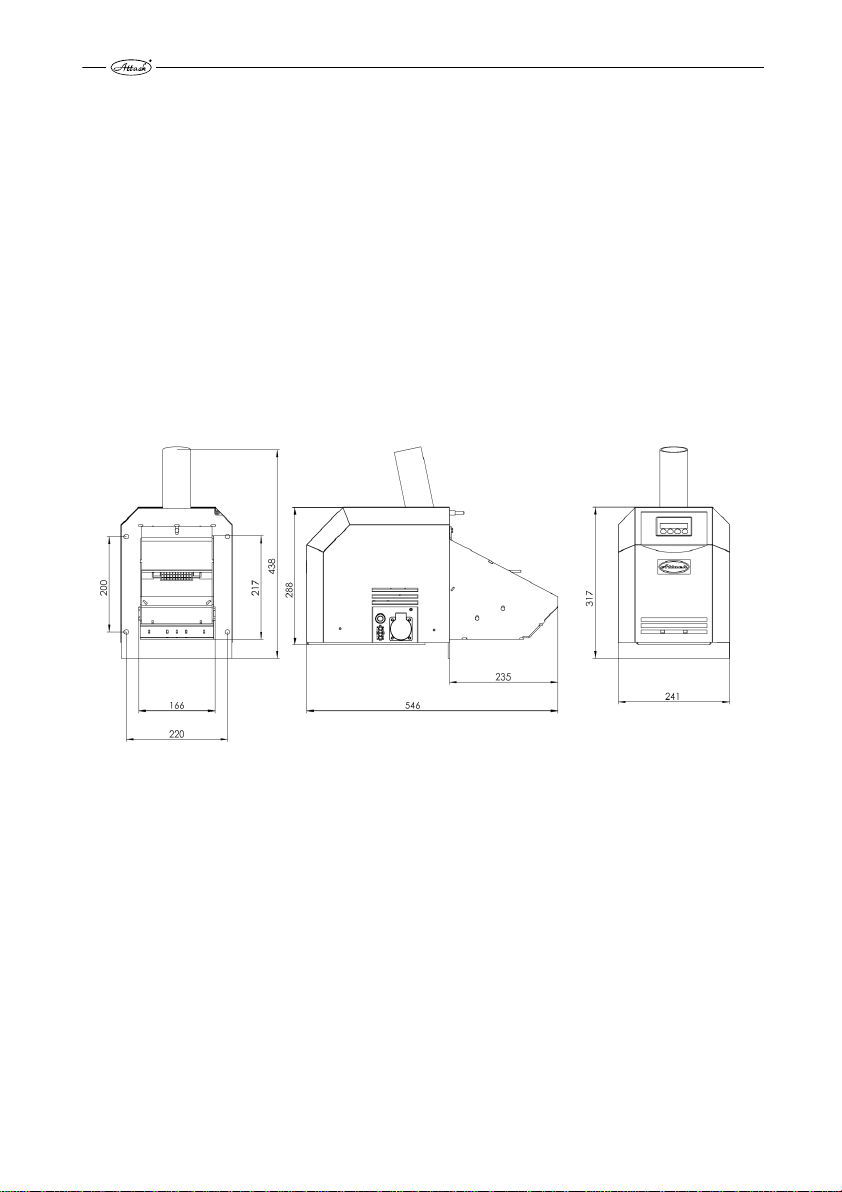
Dimensions / Contents of delivery
The PELH30A is delivered in a paper box filled with polysthyrene to improve stability. If the box is
damaged, check the burner for possible damage by transport. Claim of the damage by transport has
to be registered by a spediteur.
The paper box ought contain the following items:
1 pc. Burner PELH30A
1 pc. Inlet tube with emergency thermostat of back-burning
1 pc. External temperature sensor for the boiler temperature
4
Page 5
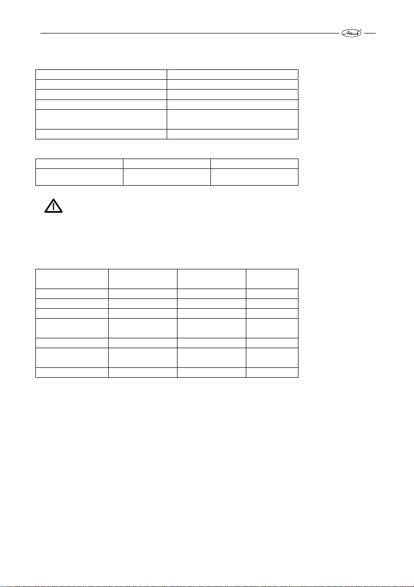
Technical data
Model PELH30A
Fuel Wood pellets, 6-10 mm
Mode 8 – 12 kW; 14 – 30 kW
Scale of output 8 - 30 kW, graduated by 2 kW
For boilers with the heat chamber up
to
Weight 22 kg
Main voltage Main current Hz
~230V 10A fuse 50
WARNING The electrical installation has to be done by a certified electrotechnician. The
main cables can be replaced only by an authorized eletrotechnician.
3 m²
Voltage and energy consumption
Component Mains/Volt Min./Max.
Display 5V DC 1 W --------Ventilator 230V~ 15-58W 800mA
Circuit plate 230V~ –------Grate cleaning 24V DC 10-50W Being
Ignition 230V~ 600W 6.3A
External pellet
feeder
Ash removing 230V~ 15-220W 1A
230V~ 15-220W 1A
Voltage
Fuse
switched
5
Page 6

Description of function
NOTE: The PELH30A works with the built-in digital thermostat, resp. with additional
room thermostat. In both cases, the burner has to be connected through fuse against boiler
overheating.
Normal start-up
When the thermostat gives instruction to the burner, the ventilator starts and the photocell controls
the fire. If there is no fire, then comes the instructi on to blow the burner through. Afterwards,
pellets start to fall into the burner within the period stated by the control system and the ignition is
activated.
After the phase of fuel feeding for ignition is finished, the control system waits for signalization of
fire from the photocell.
When the photocell recognizes the fire, small amounts of pellets fall within the transition period.
Duration of this depends on the output level set on the burner. Pellet supply is gradually increased,
until the necessary fuel amount for the required output is achieved. This amount is further delivered
into the burner, until the operation thermostat gives instruction to stop.
This signal stops the pellet inlet, while ventilator continues to supply the air into the burner.
When the photocell recognizes burn-out of pellets, the blow-through of the burner begins.
According to the adjusted delay, the burner is cleaned after the fuel burns out - the grate moves out
towards the scraper and the ash with the unburned elements falls through the front wall of the
burner´s bottom into the ashpan.
After the grate slides back, the burner waits for the new signal from thermostat.
NOTE: the unit for the grate moving is very strong and it might cause a threat. Never put
any body parts or foreign articles into the burner, while it is working.
Normal start-up, when there is still fire in the burner
If the photocell recognizes the fire during the beginning phase (e.g. after the short-time current
shortage), the control system directly begins the transition-phase and the pellet burner continues to
operate as by normal start. (see above)
Normal start-up, when the control system does not recognize the fire
The normal start-up process follows, also when the control system does not receive the fire signal.
Shortly after, the system begins the new start-up trial with fuel amount reduced for ignition by
approximately 45%. This amount can be reduced within the whole ignition period. These
parameters are adjustable only by the trained person in service menu. If the second trial fails, all
functions are turned off and the alarm is activated. This alarm is indicated on display.
NOTE: Make sure that the sufficient flue gas temperature was reached. It has to be at least
60°C - one meter under the chimney top. If the temperature is lower, consult it with your
chimneyer. The flue gas temperature lower than 60°C during the combustion process increases risk
of the chimney damage by condensation.
6
Page 7
How to use the pellet burner
The pellet burner needs air for combustion, so the boiler room has to have the air channel . The air
channel for the air inlet must have at least the same surface as the chimney and it must be opened.
The pellet burner must not be started, until it is safely approved that the smoke can freely go
through the boiler and the chimney into the environment.
Pellets are supplied into the PELH30A by the external feeder connected to the pellet container. For
better function and the most balanced feeding, the feeder should be fix ed under the angle of 45°.
The feeder should be able to feed at least cca 10 kg of pellets per hour of the continuous operation /
demand for pellet supply.
Pellets have to be stored in a well ventilated room without moisture or in a specially adjusted
container.
NOTE: The PELH30A consists from the components of high quality that must not be
replaced with the spare parts of lower quality. If the components are repl aced with other than the
original spare parts, the validity of warranty expires.
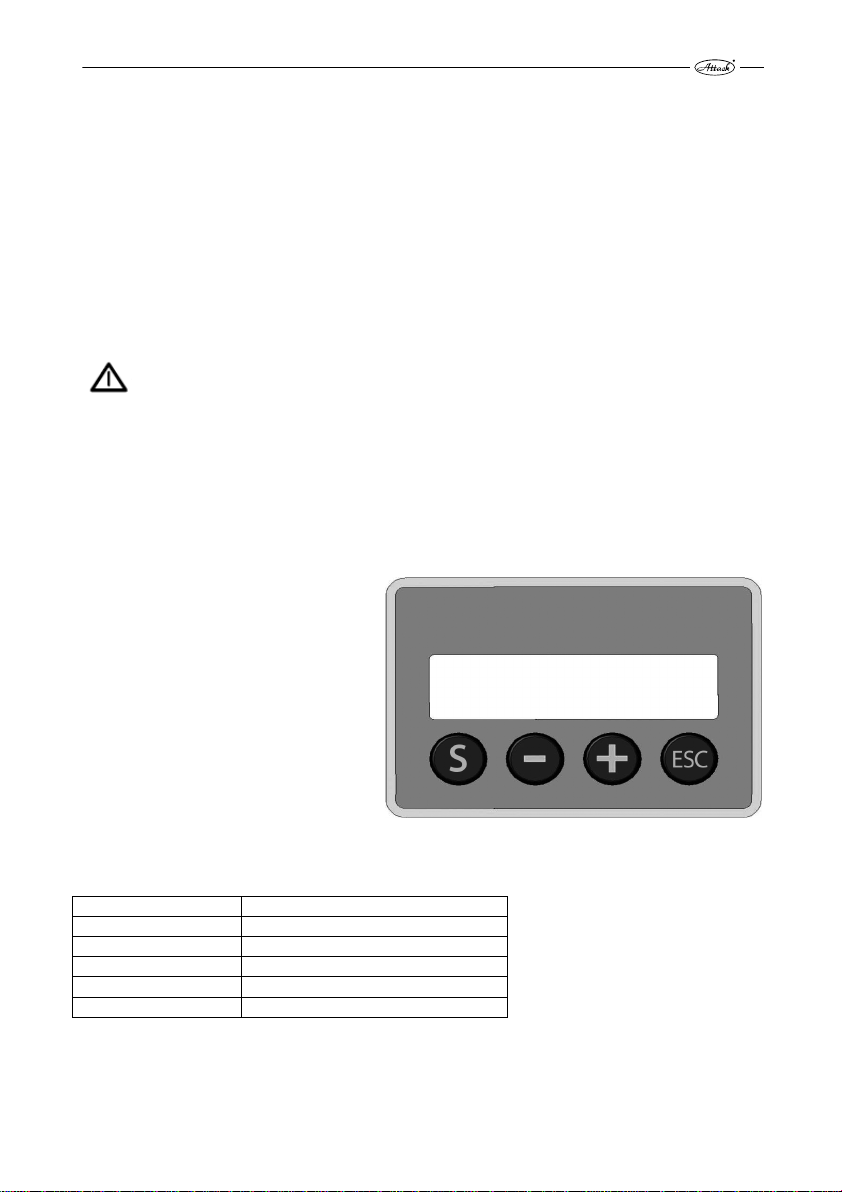
Menu buttons and their functions
Funtions of the burner are set via the menu buttons under the display. (see also options of settings
under the Production settings, below).
How to change settings of the pellet
burner:
„S“ Menu/Enter: For activation of further
records and ENTER/SAVE of the
changes.
„–“ For comeback in menu and reduction
of the adjustable values.
„+“ For advance in menu and increasing
of adjustable values.
„ESC“ Exit/Escape: For exit from menu
without saving the new values.
Values that can be set by the user are given in the following schedule:
MENU Explanation
EFFECT ADJ. Required output degree (1, 2 or 3)
PELLET-TRIM Setting of the pellet ration supplied
LOG Record of faults for control purposes
FINAL COMBUST. Instruction to burner for burn-out
MENU/ ADVANCED Access into service menu via code
7
Page 8

Indications on display
Emergency mode
PAUS.
OFF FC: 0 %
Thermostat starts.
Step 1 Test blow-through
TEST BLOWING
ON FC: ? %
Step 2 Fuel ration for heating up
IGNITION 1
ON FC: ? %
Step 3 Transition phase
TRANS. PHASE ??KW
ON
Step 4 Combustion
COMBUST. ??KW
ON FC: ? %
Step 5 Burn-out
FINALCOMBUST.
OFF FC: ? %
Step 6 Cleaning
SCRAPING
OFF FC: 0 %
Step 7 Ash removal
ASH AUGER
OFF FC: 0 %
FC: ?
%
Nothing in the burner is started, burner waits for the signal from
thermostat to start.
The fan starts to operate and when the photocell recognizes the
value under 5%, the program continues.
The fuel ration for heating up is supplied into the burner and
program waits for the „fire“ signal from photocell.
The transition phase begins, when the photocell and the control
system recognize the fire. Small, gradually increased amounts of
pellets are feeded into the burner, until the required pellet ration is
achieved.
The combustion phase runs, until it is interrupted by the thermostat.
The thermostat interrupted the combustion phase and the burner
begins the phase of burning-out.
The grate moves out and when it is out completely, the fan runs at
full rotations, until the grate moves back.
After expiration of the set period (e.g. 6 hours), the burner starts
auger for ash removing for adjusted time (e.g. 3 minutes).
Step 8: Comeback into the standby mode.
8
Page 9

Menu Indications
PAUS.
OFF FC: 0 %
EFFECT LEVEL
ENTER EXIT
Press the ”+” button.
PELLET-TRIM
ENTER EXIT
Press the ”+”button.
FINALCOMBUST
ENTER EXIT
Press the ”+”button.
LOG
ENTER EXIT
Press the ”+”button.
MENU/ADVANCED
ENTER EXIT
The burner is in the standby mode.
Press the”S” button.
Here you can change the burner output. Level 1 = 8 (14) kW, 2 = 10
(22) kW, 3 = 12 (30) kW.
The range and the levels of output are adjustable in th e advanced
menu.
Here you can set the pellet amount to be supplied. It is not
necessary, if the correct pellet weight was set in the Pellet dosing in
the service menu.
If you wish to clean the burner or to interrupt the operation from
other reasons, press the „S“ button, and the burn-down mode
begins. To restart the burner after ash removing, press the „S“
button.
This internal setting can be helpful by troubleshooting, if the burner
stops and the alarm is activated. The last 10 different error codes are
recorded. For more information about the error codes, see the
„Troubleshooting“.
To enter into the advanced menu you need password (code) and it
is necessary to know the program functions of the burner.
9
Page 10
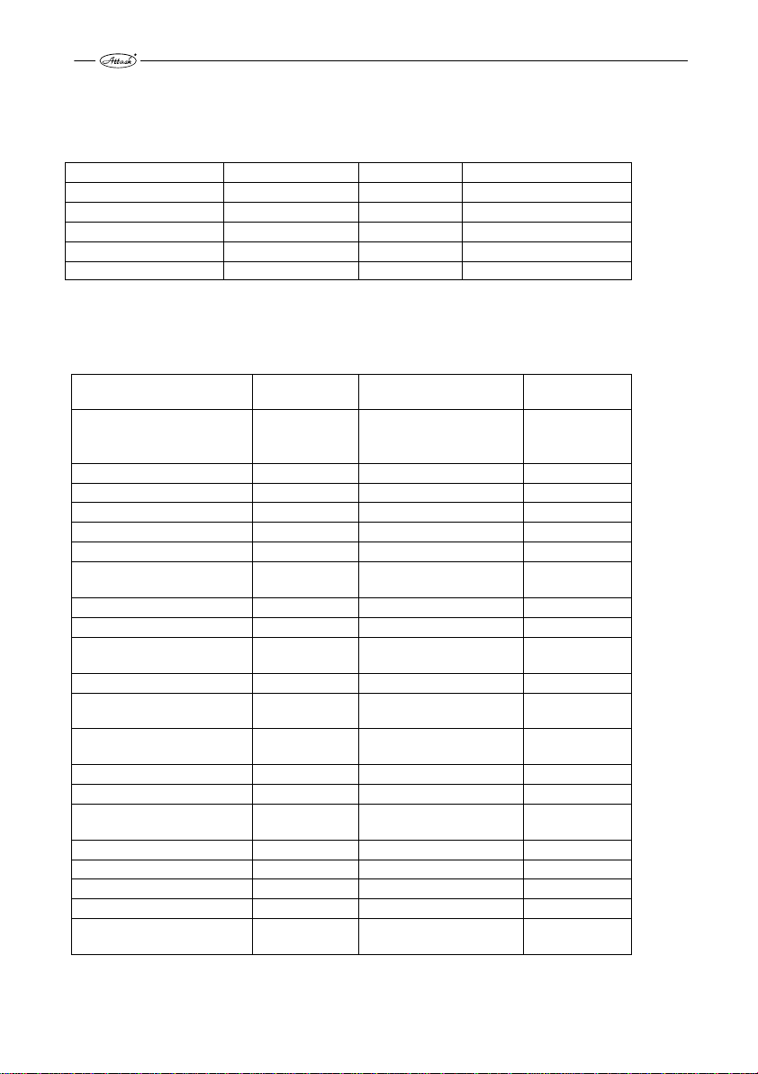
Production settings
Generally accessible menu:
Menu Settings Option Adjustable
Effect level 1 = 14 kW 1, 2, 3 8-30 kW
Pellet-trim 95 % 50-200 % 50 – 200 %
Final combustion 90 sec. 10-600 sec.
Log 10 – 26 Not adjustable
Advanced menu Random number + 5 Not adjustable
” Log ” means, that the control system saves last 10 error codes. See also the „Troubleshooting“.
Advanced menu
Advanced menu
Effect adj. 1, 2, 3,
Ignition setting 90% 50 – 300 % %
Test-blow time 15 0-60 sec.
Transition phase 240-480 60 - 600 sec.
Transition pellet-trim 15 10-50 %
Clean-blow time 45 10 - 600 sec.
Ash auger Run
Interval
Max. comb. time 360 0 - 1080 Min.
Anti-cycling 10 0 - 60 Min.
Modulation effect
Photocell (sensibility) 50 40-80 %
Thermostat External Extern./Intern./Comb.
Cleaning active
Start if thermostat 1 Turns off
Language *) ENGLISH
Effect span 1 0 (8-12), 1 (14-30)
Stoker adj. heat.
amount
Fan factor 95 10 - 500 %
Stoker time 0 hour
Menu/ Test Auto/Manual
Menu/ Settting See Advanced
Menu / Log Saves the error
* ) Languages: Slovak, English, German, Italian, French, Polish.
Production
settings Min. – max. Unit
8 – 12
14 - 30
0 – 10
1 - 200
0 – 100
1 - 100
0, 1
Turns on/off
45-50
0 - 2000
See Advanced
∆T
8, 10, 12,
14, 22, 30,
3
6
75
10
with room thermostat
46
1100
codes
Not adjustable
kilowatt
kilowatt
Min.
Hour
%
K
10xkwh/kg
g/6 min.
10
Page 11

How to change production settings
To change the settings, select the required menu/parameters. By pressing the „+“ button, change the
actual values. O: ...shows the actual temperature, N: ...can be changed to the new value.
It is possible to increase the values by „+“ and t o decrease them by „-“. By the „S“ button is the
change confirmed and saved. If you do not wish to save the values, press the „ESC“ button
(Exit/Escape).
Please, do not make any changes, until you have not read this manual.
Example:
EFFECT ADJ.
O: 1 N: 2
Comeback to the production settings
To reset the production settings, select the advanced menu and enter the password (code number
after „O“+5). Then, select the Menu/Setup and press the „S“ button. This st arts the reset of the
production settings.
Here you can also save your own settings, in the following way: by pressing the „+“ button go to
„Save settings?“ and save your settings by the „S“ button. Exit menu by the „ESC“ button.
Regulation of the pellet dosing
Before starting-up the burner, it is necessary to set the pellet supply through the parameter of the
„Stoker Adj.“ in the Advanced menu. Thermostat cannot start the heating while the settings are
being made.
Firstly, set the parameter of the „heat value“ to the value given by your pellet supplier. If the
supplier gives 4,8kWh/kg, set the parameter to 48, etc.
Now, put the plastic bag around the opening of the pellet feeder. Then, confirm by the „S “ button
and keep the instructions. Weigh the pellets fallen into the plastic bag, put their weight in gramms
via the „+/-“ buttons and press the „S“ to save the values. This setting has to be done within 15
minutes, otherwise the burner switches to the stand-by mode. Weigh the pellets very exactly!
After setting of the above mentioned parameters, the control system automatically sets all the
parameters relative to the pellet feeding.
11
Page 12

How to install the pellet burner
The pellet burner PELH30A can be installed only by a qualified, specifically skillful personnel.
The door mounted on the boiler from production has to be exchanged for the burner door.
Fix the burner on the door by the delivered screws and nuts. Connect the inlet pipe to the pellet
feeder under the required angle. Fix the inlet pipe into stable position and fasten the clamping
screws.
Undo the internal door from the boiler and put the partition of the combustion chamber into the
upper chamber.
Install the pellet container and the pellet feeder. There should be a height gap between the feeder ´s
opening and the inlet pipe of min. 400 mm. In the horizontal position there should be a gap between
the inlet pipe and the feeder´s opening of min. 1500 mm (i.e. not vertically aligned).
Fill the container with pellets and connect the feeder into the mains socket (230V~). Let the feed er
run, until you reach the continual pellet feeding. We recommend to fix a plastic bag to the feeder´s
opening to collect the falling pellets. Disconnect the feeder from the mains socket. Install the inlet
hose between the feeder´s opening inlet pipe and adjust the length of the hose.
Hose should not be straight, nor too incurved, to prevent pellets from stucking and cumulating.
Connect feeder into burner´s socket.
12
Page 13

Burner start
By turning the boiler´s main switch on, is the burner automatically turned into the stand-by mode.
Burner is put into operation by turning the burner´s switch on. Following the dem and for heat
supply, is the burner ignited and burns pellets, until the thermostat gives instruction to stop.
The burner is alternatively controlled by the thermal boiler sensor connected to TS1 inlet on the
right upper side of the circuit board. Make sure, that connection is fixed into its position. The
electrical fuse protects the burner against the overvoltage (pic.).
Burner stop
The burner stops by the turn-off-signal of the boiler therm ostat, by turning off the burner´s switch
(stand-by mode, or via Burn-down = Final combust. ) initiated per menu.
Emergency stop
NOTE:
In case of emergency, the burner can be turned off b y the main boiler switch and by plugging-out
the boiler´s mains cord from the mains socket.
Installation of the room thermostat
Disconnect the connectors that are plugged into
the control electronics. Undo the holder with
control electronics and plug the conductors of the
room thermostat. Disconnect the interconnection
cable from the terminal (Pos. 8 and 9) and connect
the cables of the room thermostat. Then, mount
the holder with control electronics back and plug
the connectors.
13
Page 14

Cleaning and maintenance
It is necessary to clean the burner after every consumption of 2000 kg of pellets. It is based on
presumption, that the quality pellets are being burned.
Furthermore, it is recommended to sweep exchanger´s parts of the boiler at least twice a month.
Clean the pellet inlet into the burner by a brush for bottles or other suitable tool.
Scrape the ignition board and the grate and clean the holes in the grate.
NOTE:
Keep ash in closed containers from non-flammable material.
Maintenance once a year or in a case of need (by a qualified person)
Start the burn-down by the menu buttons and wait, until the fuel in the burner burns-out. Turn the
burner off by the burner switch and by the main switch, plug out the mains cord of the boiler from
the mains socket. Open the door with burner to cca 90°.
Put down the burner cover and wipe the photocell by a rag and a soft abrasive agent (tooth paste).
Be carefull by the flat cable of display and buttons!
Clean the air wings of the fan. The most suitable way is to blow them with compressed air.
Screw out the scrape and ignition board.
Clean the space behind the ignition board.
Scrape ignition board and scraper.
Brush the grate utterly and clean the holes in the grate.
7. Mount all the parts back.
8. Clean the container and the pellet feeder from dust and small dirts.
9. Check state of the inlet hose for pellets.
10. Put the pellet feeder into operation by plugging of the feeder´s mains cord into the mains
socket (230V~) to fill it with pellets.
11. Set the amount of pellets to be supplied.
14
Page 15

Trobleshooting
Burner turned off.
Check, which alarm is displayed.
If the display is black and without text, check the thermal fuse of the boiler. If there is no error,
probably is just the burner´s thermal fuse turned off. To start again, turn the power supply into the
burner off, remove the cover and press the small button between the connections of the fuse of
overheating. The thermal fuse is placed directly in the fuel-inlet tube. After restart, mount the cover
back and turn on the energy supply. Thermal fuse of the burner is switched off at the temperature of
93°C.
Signal text on display Explanation Error code at
ERROR: IGNITION FAILED 10
ERROR: FIRE LOST DURING
COMBUSTION
ERROR: FIRE SENSOR Faulty photocell, abnormal
ERROR: CIRCUIT BOARD
OVERHEATED
ERROR: TEMPERATURE SENSOR
„TOO LOW“
ERROR: TEMPERATURE SENSOR
„TOO HIGH“
ERROR: OPTO-SWITCH Faulty circuit board 16
ERROR: FAN ALWAYS ON Ventilator rotates, when it is
ERROR: FAN STOP Ventilator is stopped, when it
ERROR: FAN SLOW Ventilator rotates too slowly 20
ERROR: IGNITION 1 First ignition trial failed 21
ERROR: STOCKER Pellet feeder is not connected
ERROR: BURN-DOWN FAILED Photocell recognizes signal
ERROR: LIGHT LOST DURING
BURNING
ERROR: SCRAPER NOT
OPERATING
ERROR: SCRAPER JAMMED Grate moves too slowly 26
Extinction by heating, restart
failed
light
Temperature under the cover is
too high
Faulty thermal sensor of the
built-in operation thermostat
Faulty thermal sensor of the
built-in operation thermostat
not supposed to
is not supposed to be
to the burner
also 15 minutes after setting
„Burn-down“
Photocell does not recognize
fire, restart failed
Fault in circuit board of
scraper or in grate gear
recording
11
12
13
14
15
18
19
22
23
24
25
15
Page 16

Possible causes of faults
Error
code
10 Feeder does not supply
11 Feeder does not supply
12 Short circuit or other fault of
13 Too high temperature in the
14 Faulty sensor of thermostat Replace the sensor.
15 Faulty sensor of thermostat Replace the sensor.
16 Faulty circuit board Replace the circuit board.
18 Ventilator runs, while the
19 Ventilator does not run, when
20 Ventilator runs too slowly Clean the ventilator; replace the ventilator
21 First ignition trial failed Set the pellet ration.
22 Pellet feeder missing Connect the pellet feeder
23 Incorrect pellet supply Set pellet ration.
24 Incorrect amount of pellets
25 Cleaning does not work Check the connection between the circuit board
26 Cleaning is slow Clean the grate
Possible cause Actions to correction
enough of pellets.
Empty pellet container.
Faulty ignition fuse.
Faulty ignition spiral.
Photocell needs to be cleaned.
enough of pellets.
Empty pellet container.
Faulty ignition fuse.
Faulty ignition spiral.
Photocell needs to be cleaned.
the photocell.
boiler room.
burner is in pause mode.
it should.
supplied.
Faulty photocell
Set the pellet ration.
Fill the container.
Replace the fuse. (6.3A).
Replace the spiral. (48 Ώ +/- 5%).
Clean the photocell.
Set the pelletration.
Fill the container.
Replace the fuse. (6.3A).
Replace the spiral. (48 Ώ +/- 5%).
Clean the photocell.
Replace the photocell.
Prevent from the heat leakage.
Replace the circuit board.
Change the ventilator fuse (800mA); check the
connections; replace the ventilator
Set the pellet ration.
Replace the photocell.
of scraper and the main circuit board.
16
Page 17

Decomposed view
17
Page 18

Spare parts Codes of spare parts
1. H30940A Scraper
2. H30920B Burner grate
3. H30001 Cover of the burner´s hearth
4. H30930A Ignition plate
5. PELH30900 Burning chamber
6. H30980 Ignition coil
7. TS091 Flex-cable
8. H30016E Cabling
9. H30921A Grate clamping
10. H30118C Rod of the end-switch
11. H30009 Pellet brake
12. TH31 Socket
13. H30810 Grate gear
14. TH23A Switch
15. OT19C Blocking thermostat
16. PELH30842 Plate of regulation
17. TH05A Fuse casing
18. TH06B Fuse
19. TS094A Transition
20. PR15 Silicone cuff
21. H30982 Ventilator
22. H30952 Holder of the ventilator
23. H30012A Screen of suction
24. H30961B Reduction of fuel supply
25. H30960A Pellet supply
26. PELH30830A Burner bin
27. H30701B Cover of the burner
28. H30806 Control board
29. H30808 Control panel
30. H30008 Cover with holder
31. H30002 Sealing flange
32. TS118L Flat cavity
33. H30003A Holder of switch
34. H30804 End-switch
35. H30014 Spring
36. H30803 Photocell
37. HV65 Distance tube
38. H30807 Board of grate
39. H30809 Board of display
40. H30970A Pad of display
41. H30951B Pad of electronics
42. H30820 Plastic pin
18
Page 19

El. scheme of connection, burner PELH30A
Colour marking of conductors 1 – Main electronics
1 – Brown 2 – Display electronics
2 – Yellow-green 3 - Display
3 – Black 4 – Data cable
4 – Blue 5 – Plug for feeder
6 - Ventilator
7 – Sensor of ventilator rotations
8 – Boiler temperature sensor
9 - Photocell
10- Coil
11 – End-switch
12 – Thermal fuse
13 – Board of grate
19
Page 20

Endings and connections, fuses
Placing and sizes of fuses
F1 = F800mAL250V for ventilator
F2 = F1AL250V for feeder
F3 = T6.3AL250V for ignition
F4 = N/A
F5 = F2AL250V for gear of ash removing
Accessories
Name Number
Pellet container, 350l PEL9600
Pellet feeder, 1.5 m long PED150
Pellet feeder, 2.5 m long PED250
1. 230 VAC – Phase
2. 230 VAC – Directly earthed
conductor
3. 230 VAC – Phase of thermostat
4. Ventilator – Directly earthed
conductor
5. Ventilator – Phase
6. Feeder – Directly earthed
conductor
7. Feeder – Phase
8. Ignition – Directly earthed
conductor
9. Ignition – Phase
12. Ash removing - Directly
earthed conductor
13. Ash removing - Phase
19. Earthing
20. Photocell
21. Photocell
Thermal sensor
20
Page 21

Contact person and electrotechnician
Date of installation
Installed (by
whom):
Address-street
ZIP Code, City
Telephone
Cell phone
Service record
Date
Servised/
Checked
CO2
Flue gas
temperature
CO ppm Service performed by:
21
Page 22

Advanced menu
The following data/parameters are adjustable by a qua lified person only.
All the points of the advanced menu are available by pressing “S”. The actual setting is permanently
displayed in the left bottom corner under „O:“ (time/value), whereas the new value is displayed in
the right bottom corner under „N“: (time/value).
To increase and decrease time or values, press the buttons „+“ and „-“. To confirm and save the
new values, press „S“. To exit without saving, press „ESC“.
By enter into the advanced menu, add 5 to the displayed random number. Example: it can be “18”
on both for „O:“ and „N:“. Now press „+“, until „N:18“ is changed to „N:23“, then press „S“. This
enables access into the advanced menu.
For example:
MENU/
ADVANCED
O: 18 N: 23
Output setting:
EFFECT ADJ.
ENTER > EXIT
After pressing the „S” by displayed „EFFECT ADJ.“ is in the left upper corner displayed
„OUTPUT 1 (kW)“ . In the left bottom corner will be „O:14“ (i.e. the actual value of the actuator
output in kW).
To change the actuator output, press the „+“ button, until the required value is displayed in the right
bottom corner, i.g. „N:18“. If you press „S“ now, this new value (18 kW) will be saved for the
output level 1. After this, the output level 2 is displayed („OUTPUT 2“) and it can be set to the
required value. If it will not be changed, press „S“ to save the value indicated on display, i.g.
„N:22“, i.e. the output level 2 (OUTPUT 2) will be 22 kW.
If you wish to let the display without saving the changes, press „ESC“.
Setting of ignition:
IGNITION
SETTING
ENTER
< > EXIT
was pre-set to 170 g. If you increase this amount to 110%, the starting amount will be changed to
187 g.
If the first trial of the burner ignition fails, the Ignition amount 2 is activated, which is pre-set from
production to 45% from 170g, i.e. 76,5g.
Old New
Here you can select from three outputs used like the „ACTUATOR
OUTPUTS“ as ACTUATOR OUTPUTS in the generally
accessible menu (8-30 kW).
Here you can adjust the ration of fuel for ignition in %; this value
was automatically calculated adequately to the weight given in the
Feeder setting - amount.
By pressing the „S“ button, the „Ignition amount 1“ is displayed in
the left upper corner. Changes are made in %, the starting amount
22
Page 23

Setting of time of the test blow-through
TEST BLOWING
ENTER
< > EXIT
recommended to increase the time of test blow-through. From production it is set to 15sec.
Setting of the transition period:
TRANS. PHASE
ENTER
< > EXIT
and the second is 30 kW. The time set by the first parameter determines, how long it will take to
achieve 14 kW, time of the second parameter determines time to achieve 30 kW since the fire is
recognized. The lower the required output is, the shorter is the period necessary to achieve it.
Setting of the fuel supply during the transition phase:
TRANS. FEED.
ENTER
< > EXIT
recognition. The supplied amount will be gradually increased with every ration during the stated
period. From production it is set to 15% from the full ration for 14kW.
Time setting of the cleaning by blow-through:
CLEANBLOW
TIME
ENTER
< > EXIT
Setting of the ash removing:
ASH AUGER
ENTER
< > EXIT
Setting of the maximum burning time:
COMBUST. TIME
ENTER
< > EXIT
Time of the test blow-through defines the time, within which will
be the boiler and the chimney ventilated before beginning the
combustion (10-100 seconds).
For boilers, at which there is tough to achieve their draught, it is
Here you can select the duration since the first recognizing of the
fire up to the feeding of full amounts of pellets, adjusted by the
actuator output.
There are two parameters of the transition phase: the first is 14 kW
Here you can set the fuel amounts that are feeded during the
transition phase, since the fire is recognized until the burner
achieves the output of 14 kW.
Set the required amount to be feeded into the burner after the fire
The cleaning by blow-through is activated, when the therm ostat
switches off and the value recorded by the photocell decreases
under 12 %.
The ash removing is activated automatically in the intervals set
from 1 up to 200 hours for the stated period.
By this parameter it is possible to set the maximum time of the
continuous burner operation.
23
Page 24

Setting of the minimum duration of the break between the burn-down and the ignition:
MIN. PAUSE
TIME
ENTER
< > EXIT
Setting of the time of the blow-through clening:
MODULATION.
ENTER
< > EXIT
Setting of the photocell sensibility:
PHOTOSENSOR
ENTER
< > EXIT
Selection of the thermostat:
THERMOSTAT
ENTER
< > EXIT
by pressing the „S“ button, then you can change the stop temperature. By repeated pressing of „S“
you save this value as well. The burner will now work in the range of the actually set temperature
values. There should be difference between the starting and the stop temperature of at least 5 °C.
Grate cleaning:
SCRAPER
ENTER
< > EXIT
Language selection:
LANGUAGE
ENTER
< > EXIT
Setting of the output range:
EFFECT SPAN
ENTER
< > EXIT
This parameter ensures, that it comes to the next burner ignition
only after the stated time, not immediately after the burn-down.
By the stated value of ∆T , before achieving the required boiler
temperature, the boiler output decreases automatically to the preset level.
Here you can set the photocell sensibility, i.e. the value of light in
(%), to which should the system react as to the fire. It should not
be necessary to set the light sensibility, if the correct photocell is
installed. The setting from production is: 50%.
Here you select the required thermostat: the external boiler
thermostat or the burner thermal probe, or combination with the
room thermostat.
If you use the burner thermal probe, it is possible to set 2
parameters. Firstly, select the starting temperature, save the value
By this parameter you can set, if the grate cleaning will be
activated and when it has to be turned on – before the ignition or
after the burn-down.
There is an option to select the following languages: Slovak,
English, German, Italian, French, Polish.
The burner can operate in the output range of 8 – 12 kW, or 14 –
30 kW, according to the range selected by this parameter.
24
Page 25

Adjustment of the pellet dosing:
FEEDER
ADJUST.
ENTER
< > EXIT
the bore). Put the sack on the feeder and press the „S“ button.
Check countdown on display now, while the feeder works for 6 minutes. Then, enter the weight of
the pellets fallen by pressing „+“ and „-“ buttons and confirm/save by „S“ button.
Ventilator setting:
VENTILATOR.
ENTER
< > EXIT
OPERATION
TIME OF
FEEDER.
ENTER
< > EXIT
Test:
MENU/TEST
ENTER
< > EXIT
forwards to the required part, press „+/-“. They are displayed in the following order:
Ventilator (during the test of ventilator, the displayed rotations per minute should stabilize at 2000);
Pellet feeder
Ignition coil
Grate (moves out by „S“ and moves back by „ESC“. Here you can see, how many mA are
consumed by unit during the shift, which should not exceed 1800 mA - limit to start the error
“Grate blockage”).
Other displayed options:
Current temperature, if the thermal probe is connected; current photocell value; shows light
(On/Off); closing of this application.
(start/stop by the buttons „S“/“ESC“);
(activated by „S“ and stopped by „ESC“);
= The most important parameter of the control system! Here you
can set the pellet ration supplied by the feeder at the full operation.
To set the pellet ration, you need a plastic sack and a very exact
weighing machine. After entering into the parameter, you have to
set the Heat value (kWH/kg) as the first. Then, the text „Put on the
sack“ is displayed (pellet feeder should be filled with pellets up to
By this parameter it is possible to adjust the flue gas adequately to
the flue gas analyzer for the content of CO and O2 in flue gas.
Operation time of the feeder:
Here you can see, how long did the pellet feeder work. You can
use it to calculate the energy consumption, etc.
To be used by troubleshooting. Here you can manually or
automatically control the components.
This function is very helpful by troubleshooting with particular
components. In the manual mode you can test every component
individually, by pressing „S“ for start and „ESC“ for stop. For step
25
Page 26

Settings:
MENU/SETUP
ENTER
< > EXIT
- „Loading of settings“ - means, that you can reset the original settings
- „Saving of settings“ - stands for the final input of the burner settings, made by the
installator. This eases browsing of settings, if it would come to too many parameter changes.
- „Production settings“ – are the original settings, that can be reloaded again.
Log:
LOG
ENTER > EXIT
ignitions, number of the second ignitions, the newest errors
- „Number of errors“ - displays every error code individually, e.g. E-CODE 10(X).
See the page 17 for codes and explanation.
- „Number of the first ignitions“ - displays, how many times did the ignition run.
„Number of the second ignitions“ - displays, how many second ignition trials were
made by burner (i.e. how many times did first trial fail).
- „Last errors“ - displays the codes of errors in the order according to their incidence.
It eases the troubleshooting.
The settings made during the installation are stored here, or it is
possible to reload the production or the installation settings.
Three main options are accessible: Loading of settings, Saving of
settings and Production settings.
All the errors are saved and displayed here, together with the
frequency of their incidence. Also the final number of the ignition
trials is here to be read.
There are four options: number of errors, number of the first
26
Page 27

Record about installation for warranty claim
Date of installation: 20…..-……-…...
Installed in :……..……..………………… Telephone:………………………
Street:…………………………………...... Fax:………………………….
ZIP Code and City: ………………….Cell phone:……..…………..
……………………………………………
Installed on boiler:
Trademark:.................................................... Model:……………………….
Pellet burner:……………………………... Serial number:………………..
Pellet feeder:
Trademark:……………………………….. Length:………………………..
Serial number:………………………………
Settings of pellet burner:
Menu Production
Output level 1 = 14kW 1, 2, 3
ON/OFF temperature ON 72 °C,
Pellet ration 95 % 50 – 200 %
Advanced menu Random nr. + 5 No No
Pellet ration 1100 g/6 Min.
Energy content 48 kW/10 kg 45 – 60
Installed by:………………………………………………………………
Telephone:……………………………… Fax:……………………………….
Contact person:………….…………………………………………………..
This copy is for customer.
settings
OFF 82 °C
Options of
settings
Difference
min. 5 ْ◌
Set to
27
Page 28

28
Page 29

Record about installation for warranty claim (for seller)
Date of installation: 20…..-……-…...
Installed in :……..……..………………… Telephone:………………………
Street:…………………………………...... Fax:………………………….
ZIP Code and City: ………………….Cell phone:……..…………..
……………………………………………
Installed on boiler:
Trademark:.................................................... Model:……………………….
Pellet burner:……………………………... Serial number:………………..
Pellet feeder:
Trademark:……………………………….. Length:………………………..
Serial number:………………………………
Settings of pellet burner:
Menu Production
Output level 1 = 14kW 1, 2, 3
ON/OFF temperature ON 72 °C,
Pellet ration 95 % 50 – 200 %
Advanced menu Random nr. + 5 No No
Pellet ration 1100 g/6 Min.
Energy content 48 kW/10 kg 45 – 60
Installed by:………………………………………………………………
Telephone:……………………………… Fax:……………………………….
Contact person:………….…………………………………………………..
This copy is for installator.
Please, make copy also for seller and send it there.
settings
OFF 82 °C
Options of
settings
Difference
min. 5 ْ◌
Set to
29
Page 30

Page 31

Page 32

ATTACK, s.r.o. • Dielenská Kružná 5020, 038 61 Vrútky • Slovakia
Tel: +421 43 4003 101 • Fax: +421 43 3241 129 • E-mail: kotle@attack.sk
Export – tel: +421 43 4003 115 • Fax: +421 43 3241 129 • E-mail: export@attack.sk
ATTACK, s.r.o. producer reserves the right to change technical parameters and dimensions of
boilers without previous warning.
ATTACK, s.r.o. – 07/2017
 Loading...